KingOfKYA(Travis K. )
-
I need to update this log more.
08/22/2015 at 16:13 • 0 commentsAnyways running another group buy if anyone is intrested.
http://diychristmas.org/vb1/showthread.php?4703-Raptor12-2015(ver1-5)-12-channel-NRF-Wireless
Changelog from last year:
Expanded all solder pads so its easier to get a good thermal connection.
Cut pcbs in various places so failed components can not cause a bridge.
Fuse on low voltage side just in case.
Added support for a "secret" feature that half of you know about.
Swaped SMD leds for though hole ones on scr board
Added an idiot light for 5v rail before jumper is on. -
And then read the data sheet again....
01/27/2015 at 21:22 • 0 commentshttp://diychristmas.org/vb1/showthread.php?3576-Raptor12-issues-(2014)-Version1-2&p=41663&posted=1#post41663SO ignore the posts about the 22k resistors.
-
Read the datasheet then read the datasheet again...
01/25/2015 at 21:04 • 0 commentsTHIS IS INCORRECT
I was trying to find the cause of what seam like bad components. The irf640 were failing with no good reason i could point to. So i read the data sheet again... current fine, no one would pull 16 amps. Voltage possible the upper limit is 200v and the peak of 120VAC is around 170v. SO maybe if they were marginal...
Then I read the gate voltage 2v to 4v... dam, so that explanies i i have been driving them with 5v logic from the micro a volt over the max.
I kinda forgot at some point why I added the leds.... There there to pull the gate driving current down to 3v (blue or green)or so from 5v.
I don't know when I forgot about that, anyways there is a simple as removing the 22k ohm resistors and jumpering them, will make the leds act like shut regulators.
Current should be small enofe to not cause an issues with leds over heating. It works out to just over 1ma, well with in the leds safe operatign range, -
For the NON-cheapscates
12/26/2014 at 04:07 • 0 commentsHere is a list of parts you can order from jameco to build the raptor.
http://kneale.us/raptor12/jamecoCart.csv
Also just kinda a PSA thing the IRF640s from tayda are failing more and more now so i can not recomend them anymore for that part.
A cheap sourse for the IRF640 in the use below.
-
Open source, Here is the files.
11/09/2014 at 18:39 • 0 commentsKIcad download:
Here is a zip of the full project files for kicad.
http://kneale.us/raptor12/nrfSCR1.2.zip
Also if you have your own boards made keep in mind the copper thinkness. This board is ment to carry 2 amps per channel and 10amps total but only on 2oz copper. if you use 1oz copper (most cheap pcb services) its only able to carry 1amp a channel and 5 total.
As of 11/12/2014 i still have some pcs avaliable see my forum post link for details.
-
Only a few left
11/09/2014 at 18:21 • 0 commentsAlmost out of board, i have about 7 left if you have been waiting now is the time.
http://diychristmas.org/vb1/showthread.php?2660-Raptor12-Groupbuy-Interest-only-12-channel-Wireless-)
-
Groupbuy
09/28/2014 at 04:23 • 0 commentsSelling the boards here . WHile supplies last.
-
Ver 1.2 is here
09/26/2014 at 01:39 • 0 comments![]()
![]()
![]()
-
Waiting For shipping
09/20/2014 at 03:01 • 0 commentsDHl normal takes 4 days for deliver from china to the usa:) but apparently Hong Kong customs is making thing take mutch longer, recently. Its always something...
![]()
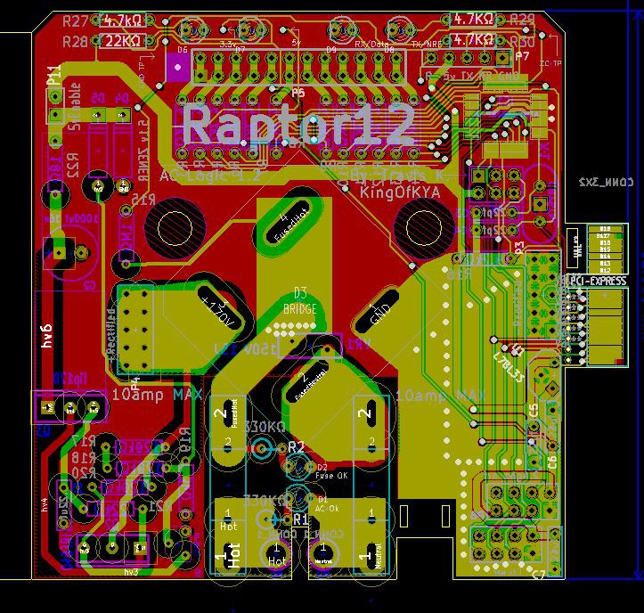
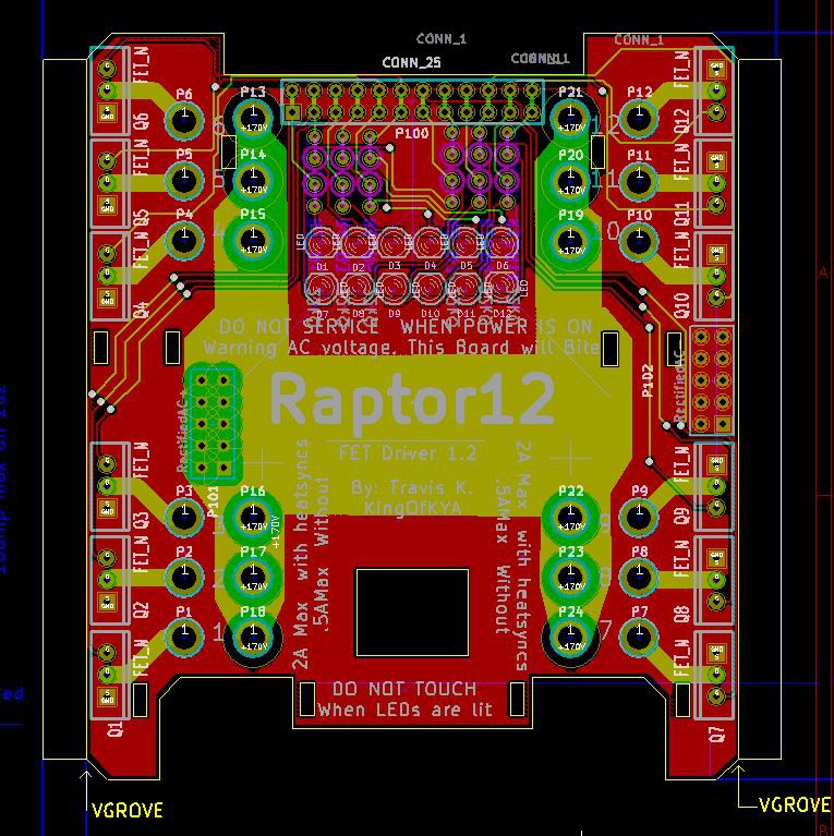
Anyway here is some pics of the pcb:
![]()
The pci-eX1 connector that just because i need an easy way to program the micro for boot loading micros for kits. it will break away after Assembly, and no you can not plug it into your pc motherboard but you all knew that already right:)
![]()
-
New PCBs 1.1v
08/31/2014 at 04:01 • 0 commentsThe issues:
ISP header takes up too mutch room. Now flipped to other side of board.
Needs an easier way to pull top board apart, new pcb will have a ziptie hole for this.
ON the second photo there is a broken resistor in the psu. This happend because it got in the way of the ta-200 screw post i shuffled a few things around to fix it.
Trace under the tip120 current limiting tranistor is too close to the tab and could cause an issue trace is now relocated to the bottom of the pcb.
OH and version now says 1.2
____________________________________________
Things that work:
Ample room for cabling between boards.
Zip ties for the output cables make repaceing the scr board very easy will be great for field repairs.
NRF modules power rail now extremely stable, thanks to via sticking the ground planes helped immensely with noise.
Dims correctly, no issues that I have seen yet. even sticking a capacitor across the output wont make dimming fail, it will on some scr/triac solutions. so long cable runs will not be an issue.
The new fet works much better IRF640, has a lower on resistance and generates very little heat compared to the irf 730 I was using previously.
See my google docs spreadsheet for fet comparison (sheet2)
Heatsync mounting soultion works great, some scrap pcb(technology edge), a heatsync form alliexpress and some thermal adhesive tape, oh and a zip tie because I don't have enofe of them yet.
http://www.aliexpress.com/item/10piece-a-lot-aluminum-heat-sink/634567803.html
http://www.ebay.com/itm/171070444248?_trksid=p2059210.m2749.l2649&ssPageName=STRK%3AMEBIDX%3AIT
![]()
![]()
![]()
![]()
![]()
![]()
![]()
Raptor12 Wireless AC Dimmer
Christmas, Halloween light string controller that is wireless, 12channel dimmable AC controller, with an AVR for $30