-
1Step 1
Woodworking
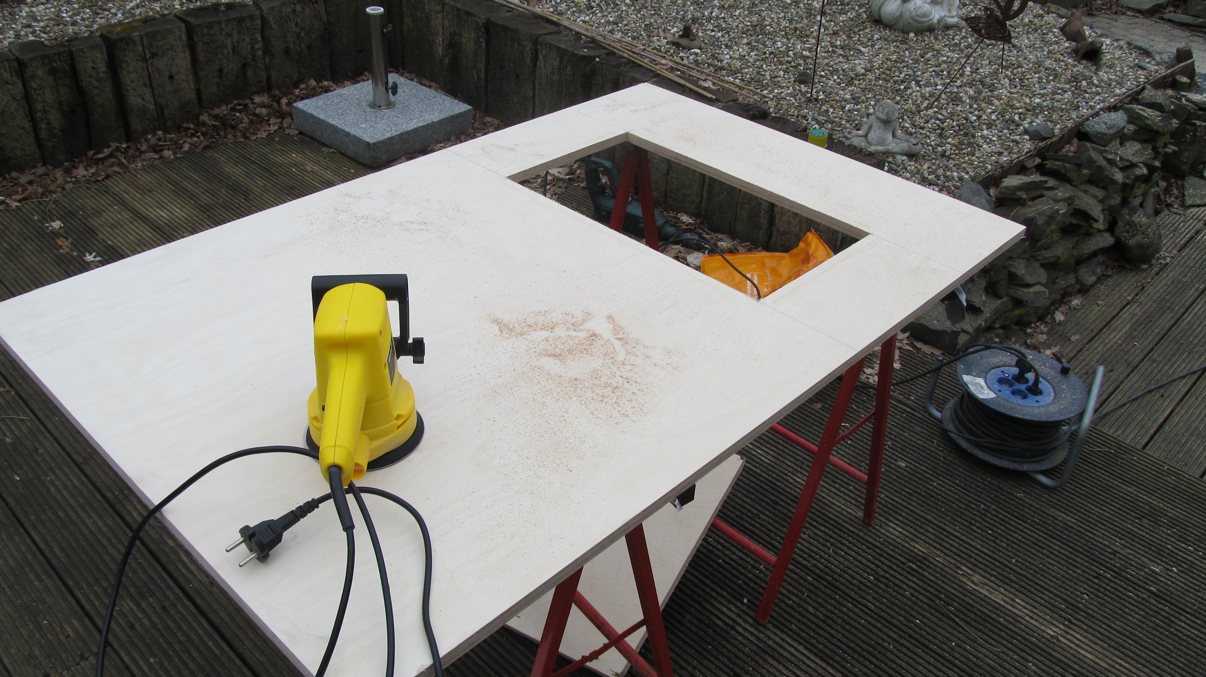
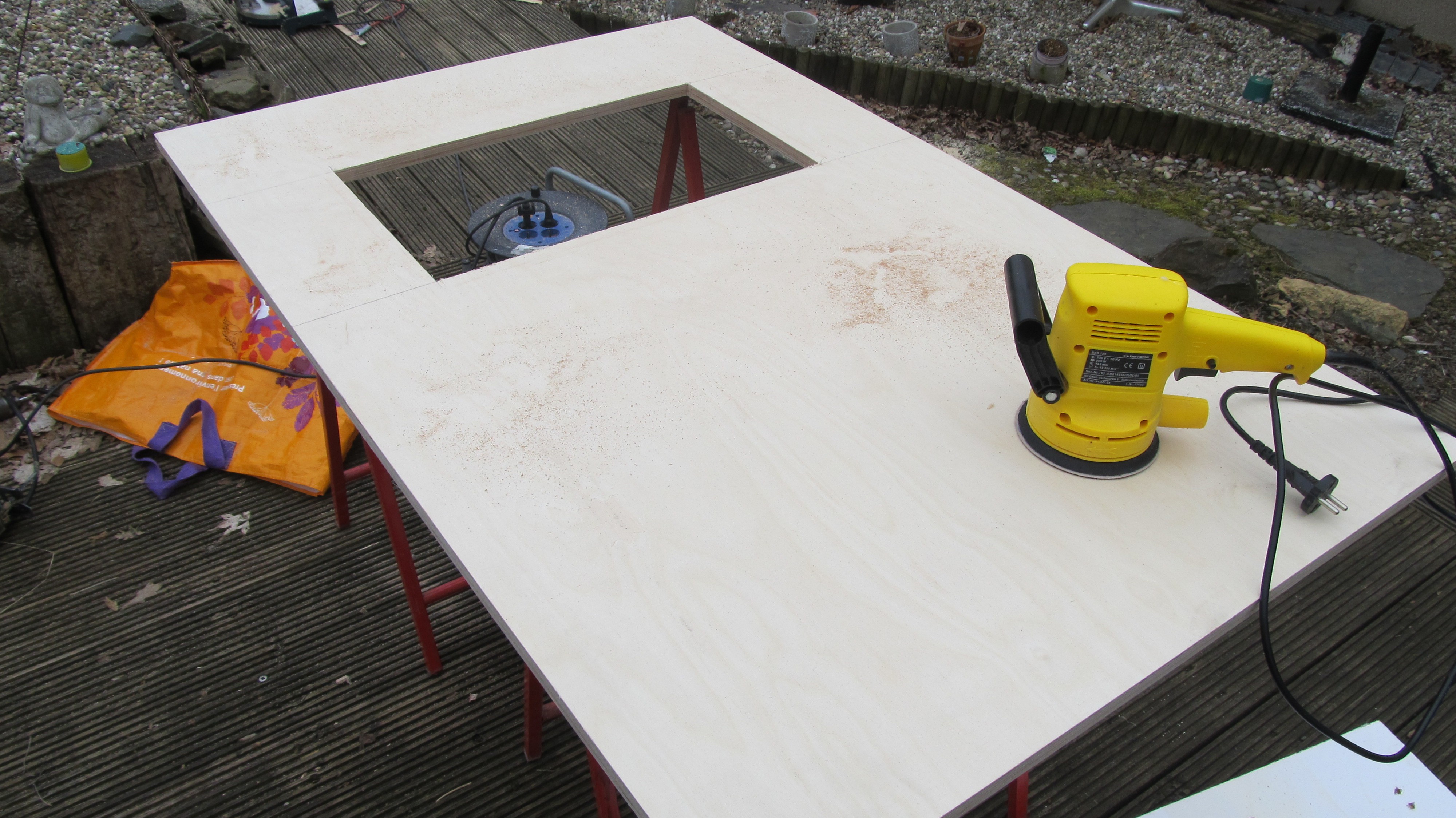
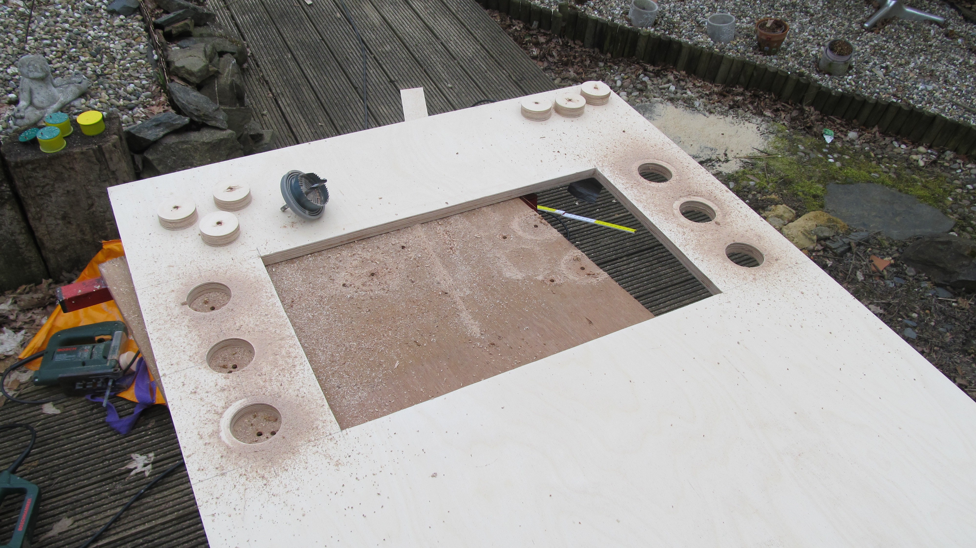
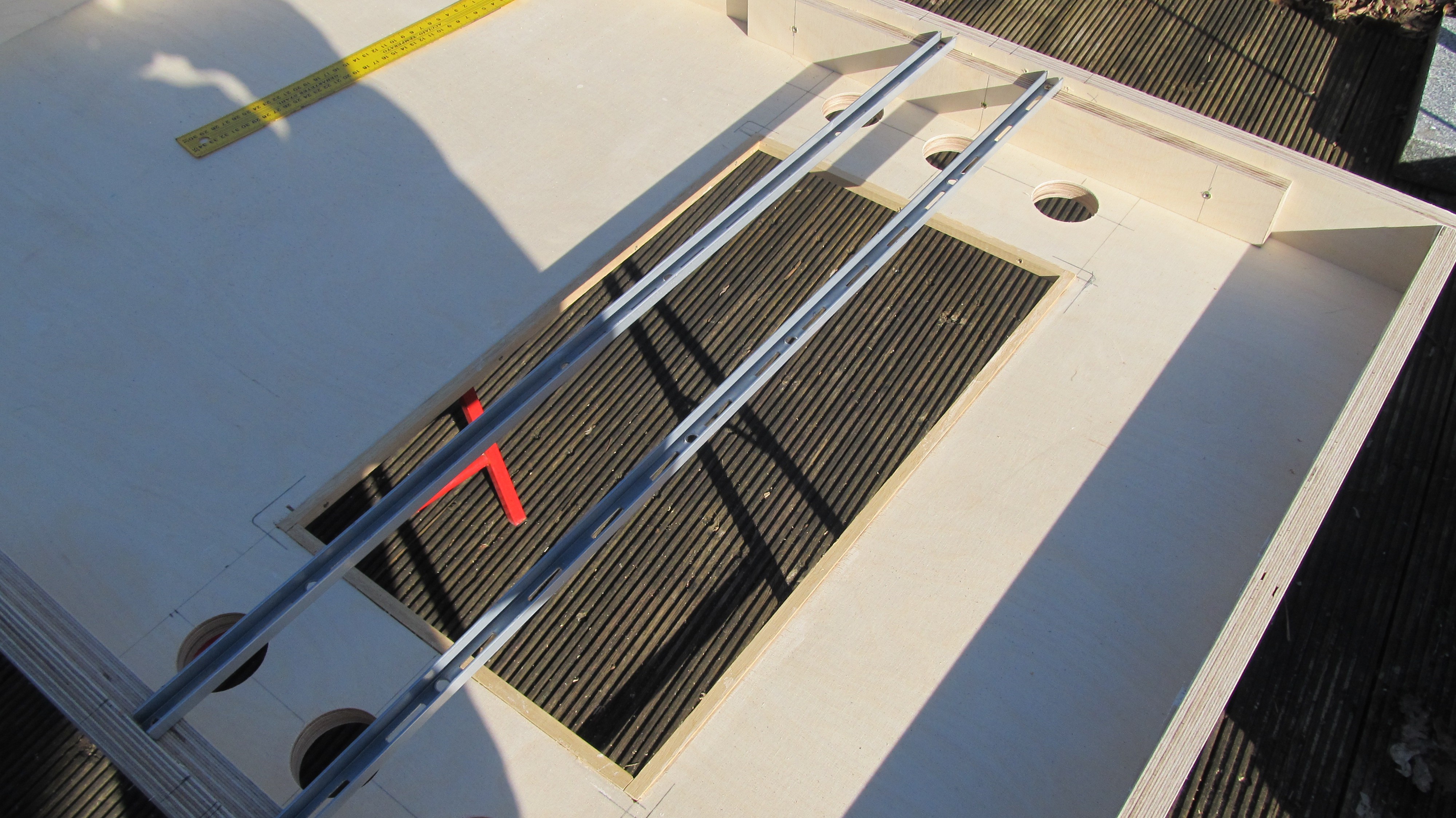
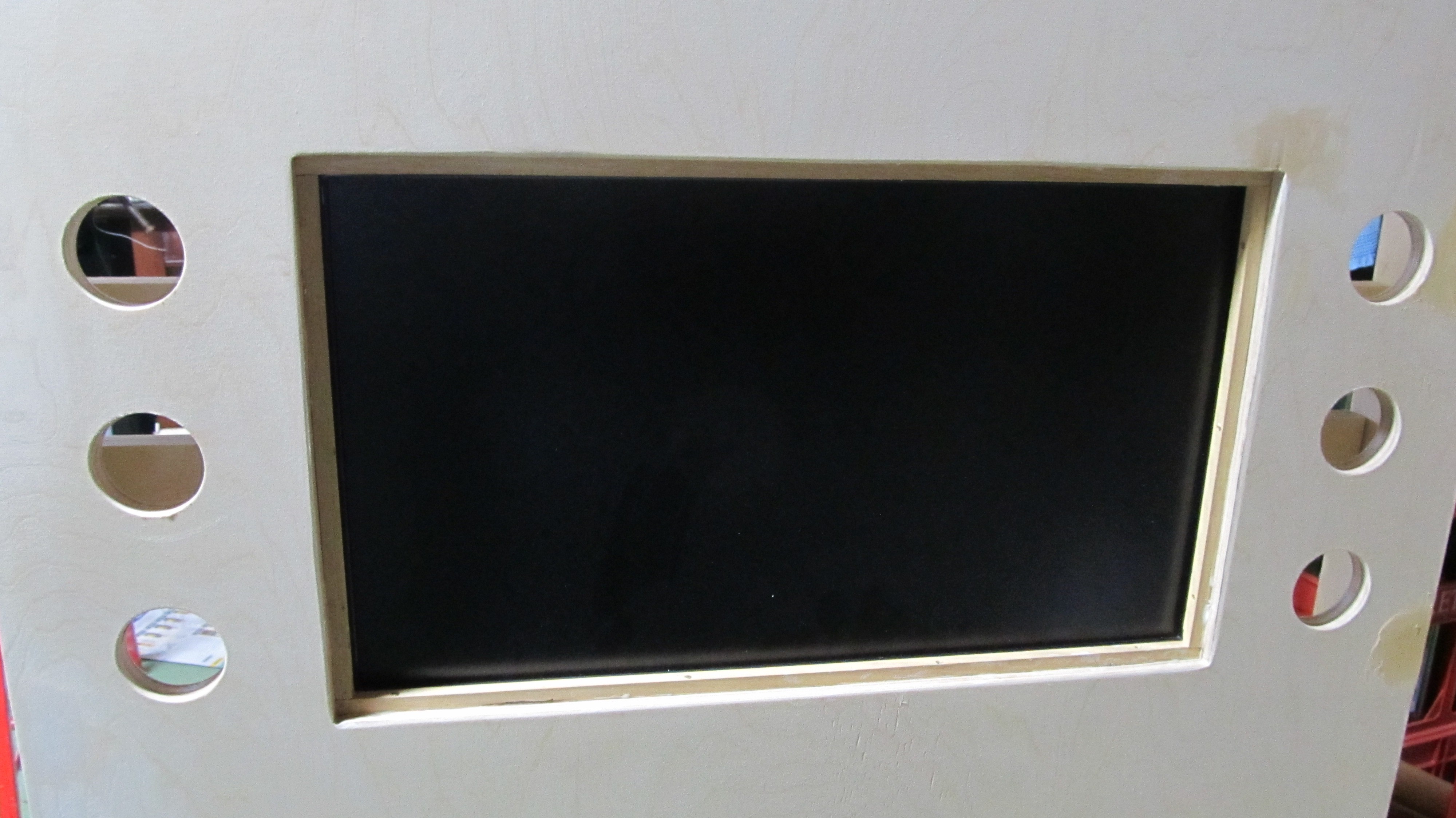
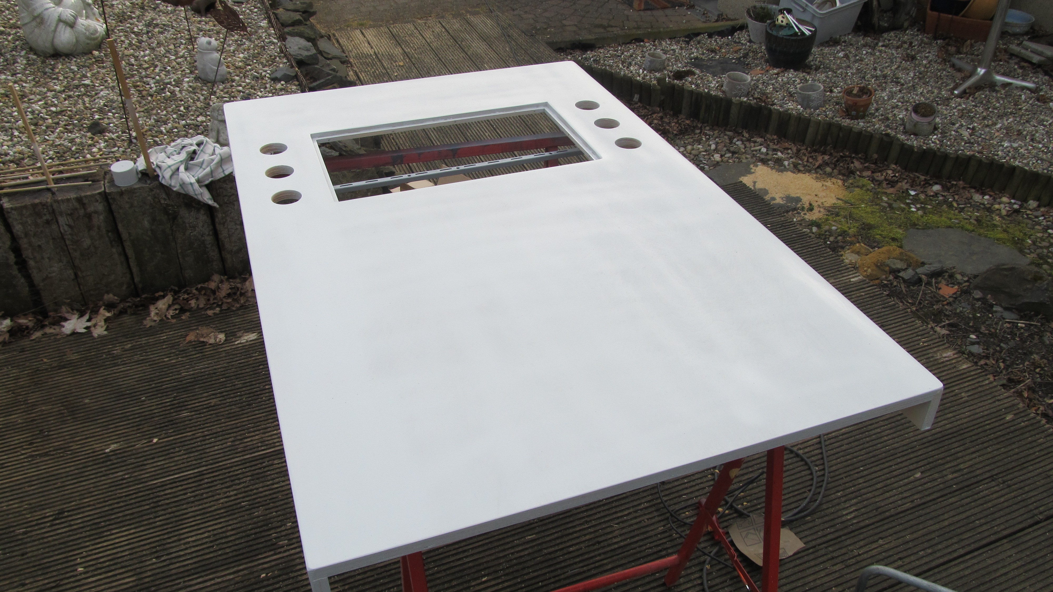
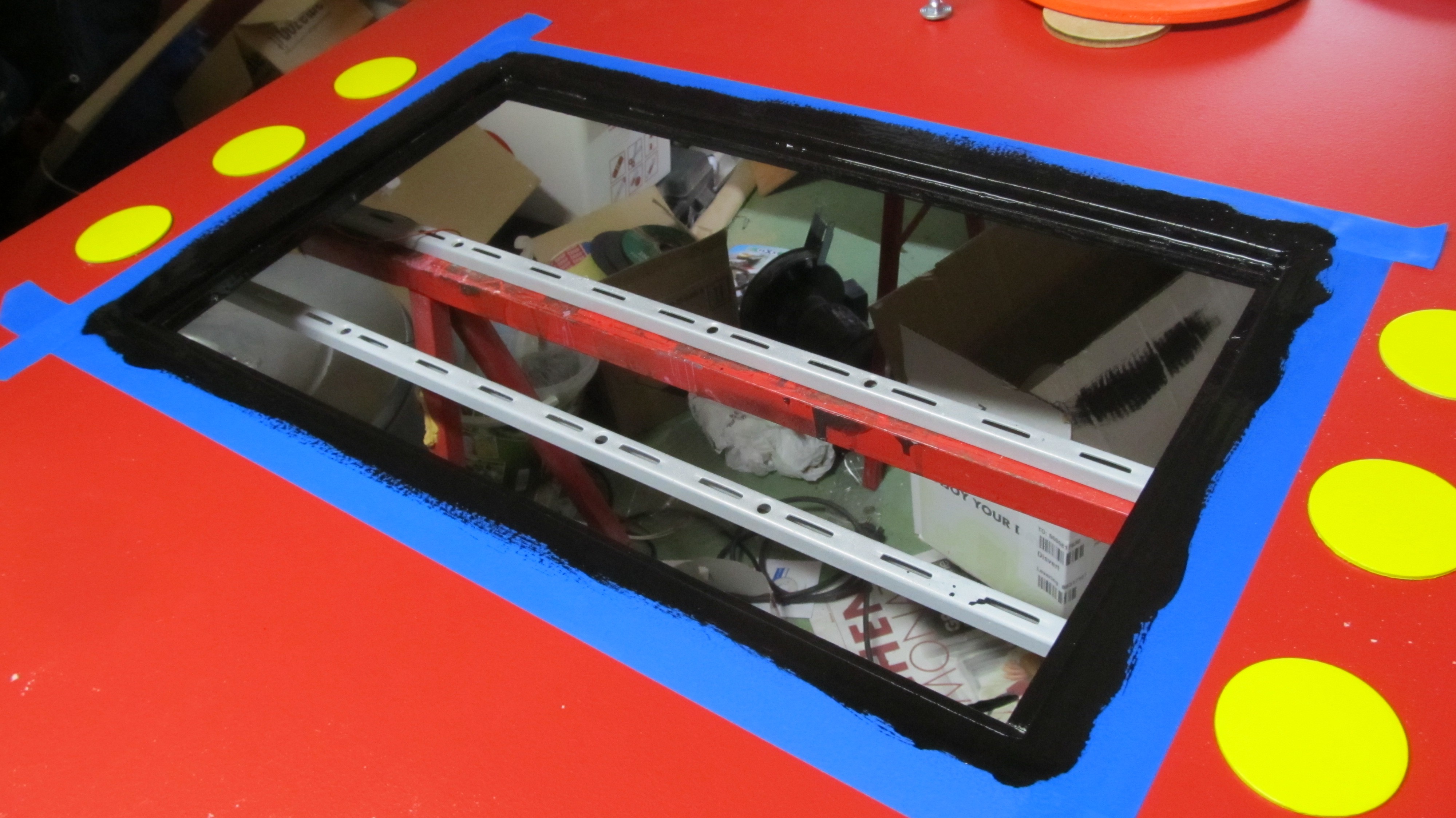
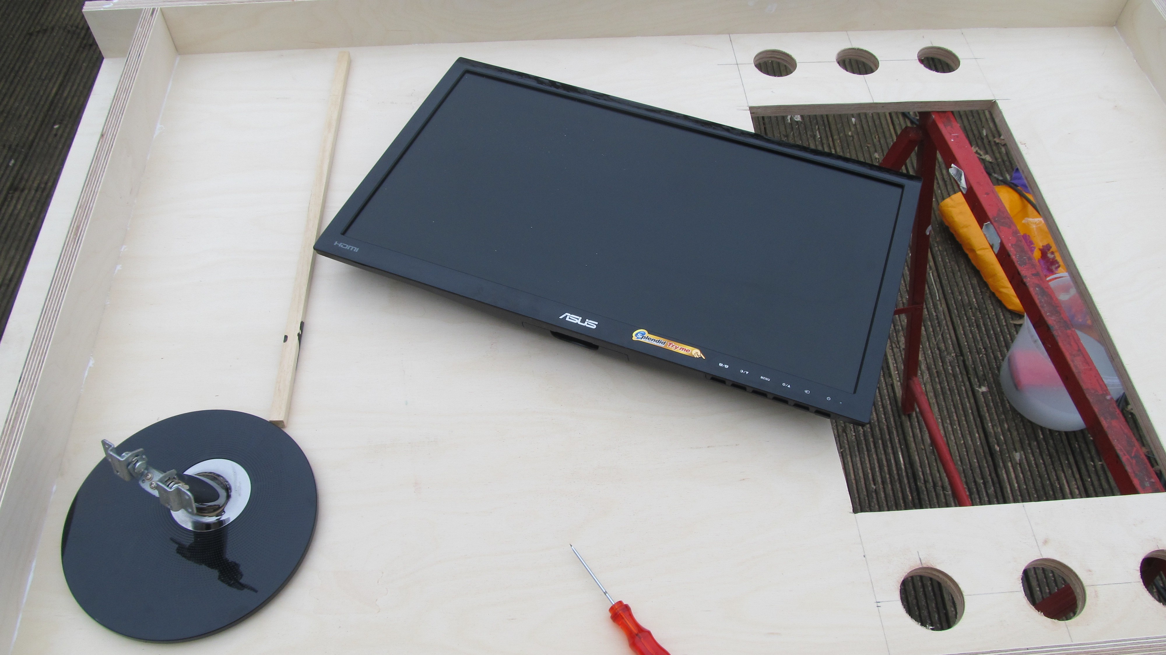
Cutting a hole in the wood plate. I took the dimensions of the LCD screen and I added 1 cm on each side. Drilling 48mm holes for the buttons and test if everything fits.
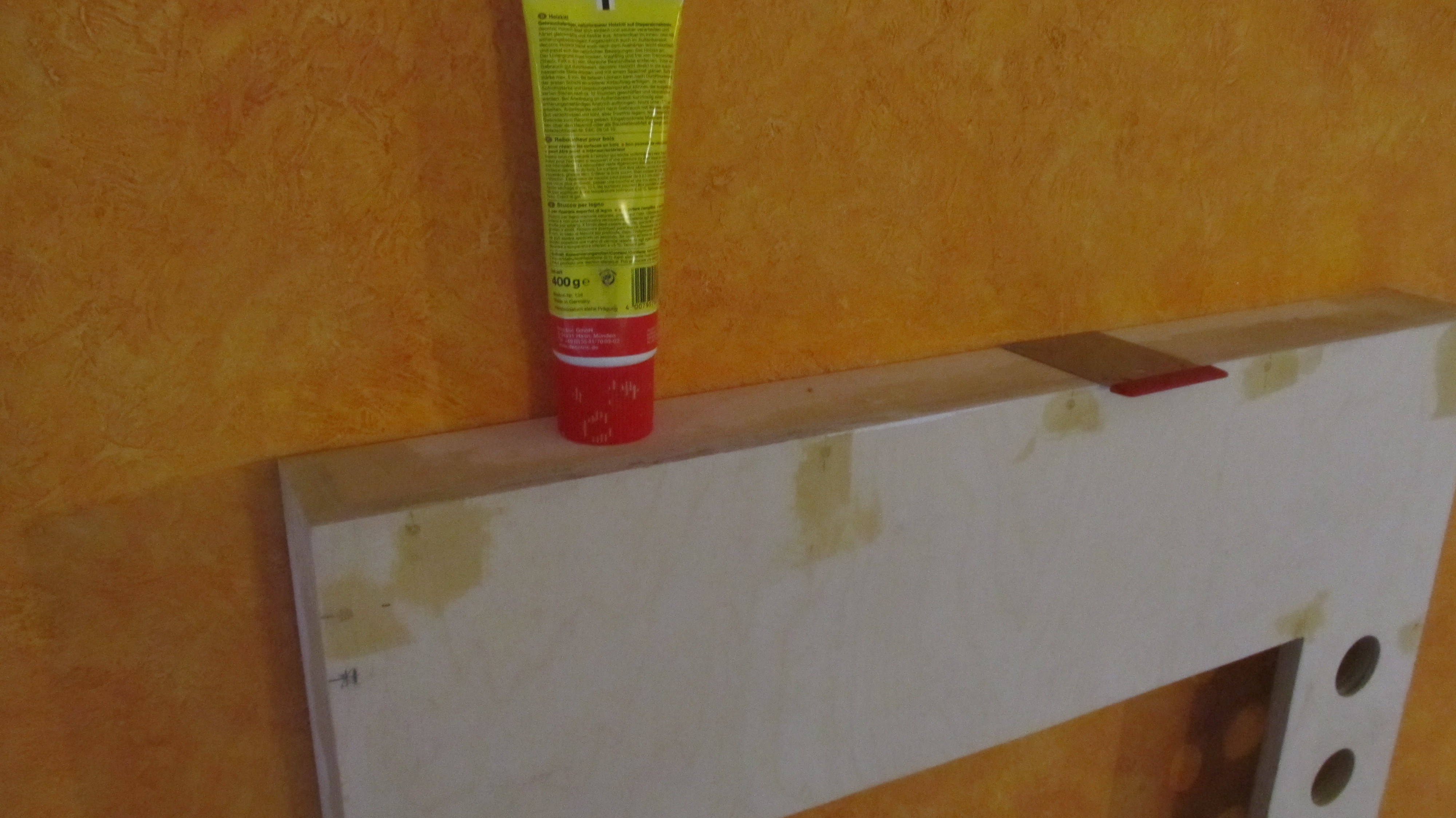
Fill all the irregularities with wood paste
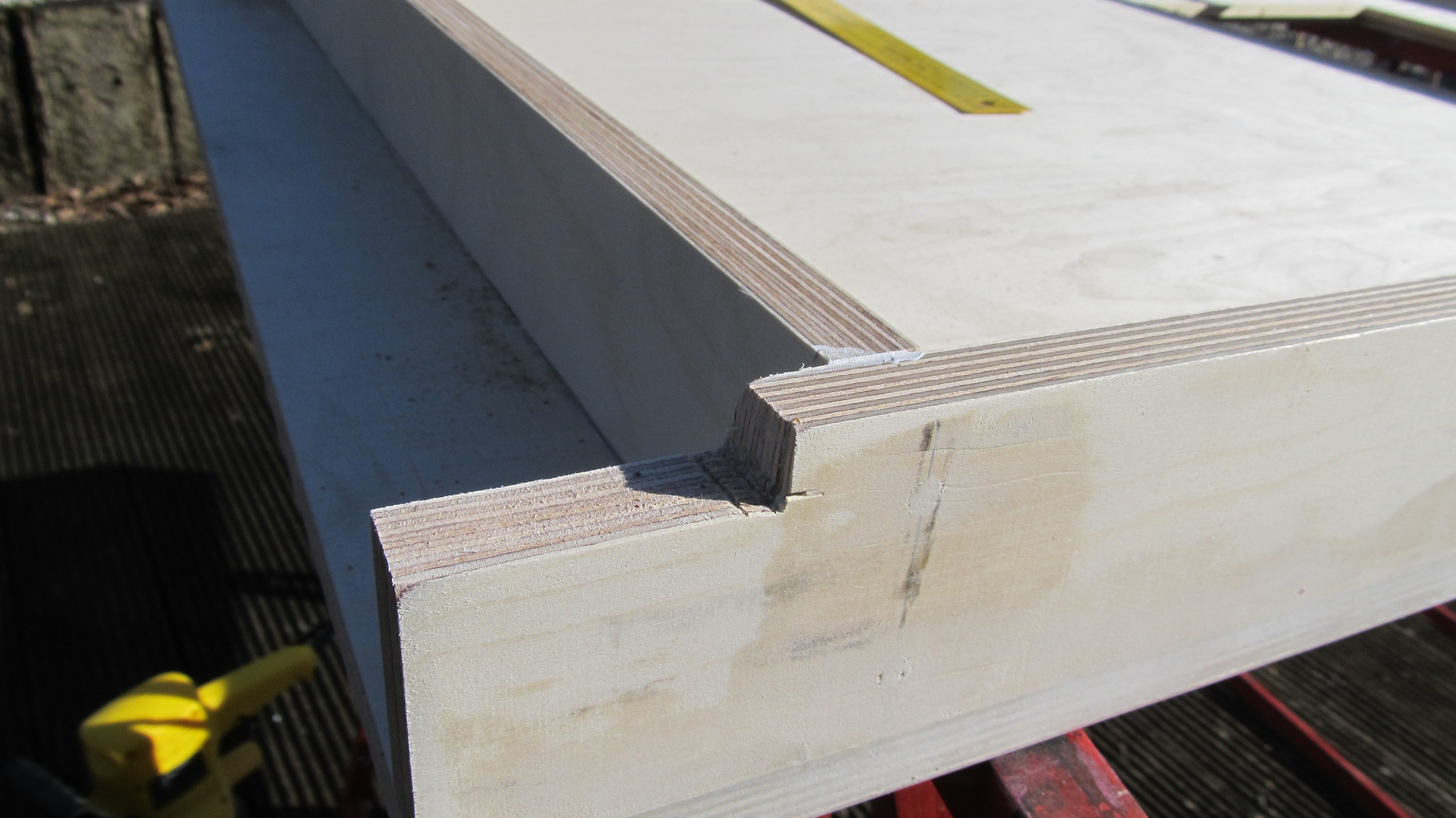
On the bottom 2 cut outs for the foot bar
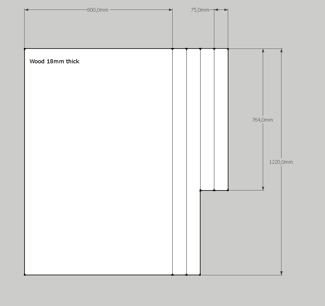
These are the sizes, i used for the construction
-
2Step 2
Paint Job
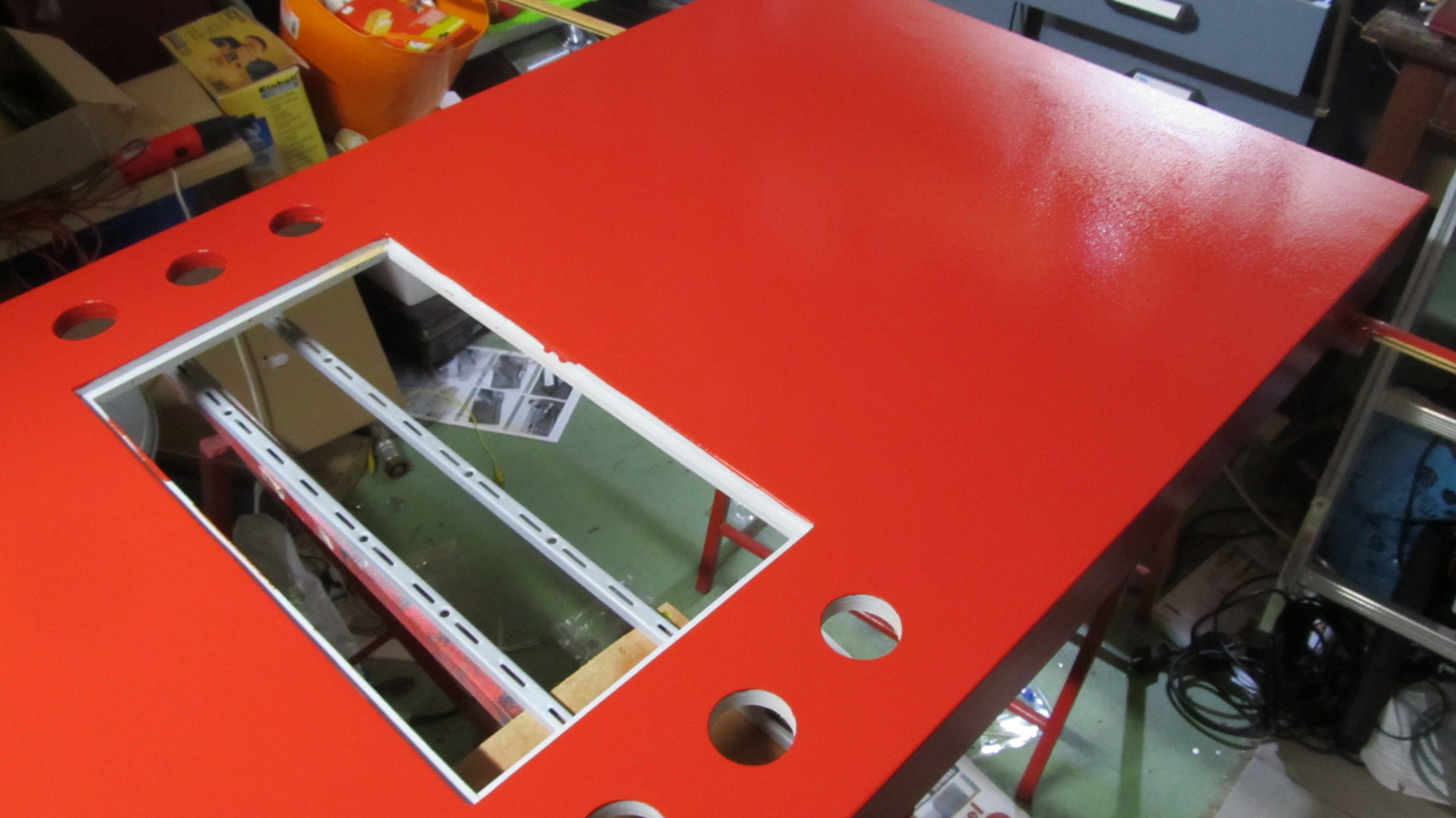
After sanding the whole thing, I sprayed a few layers of gray ground paint.
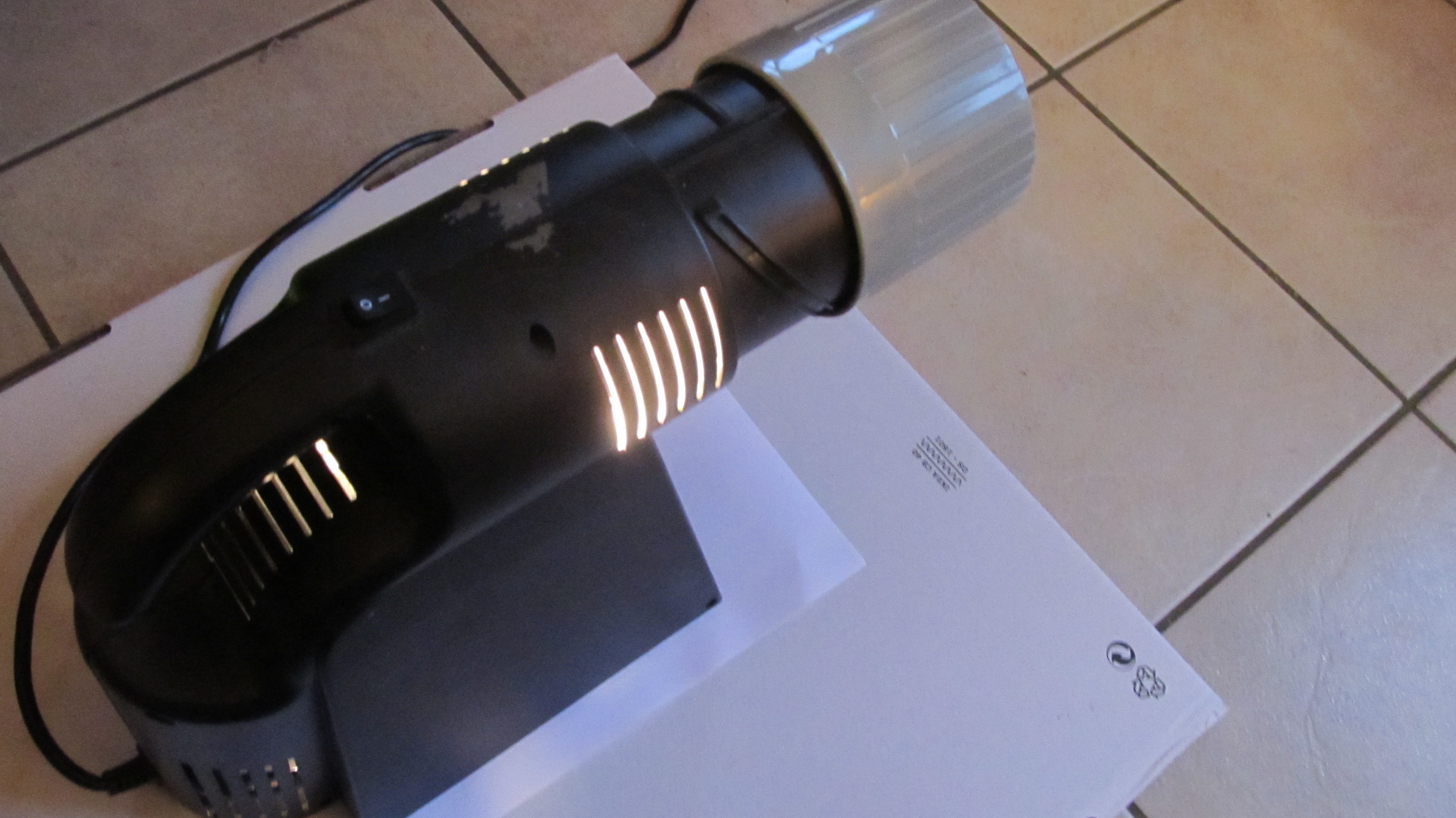
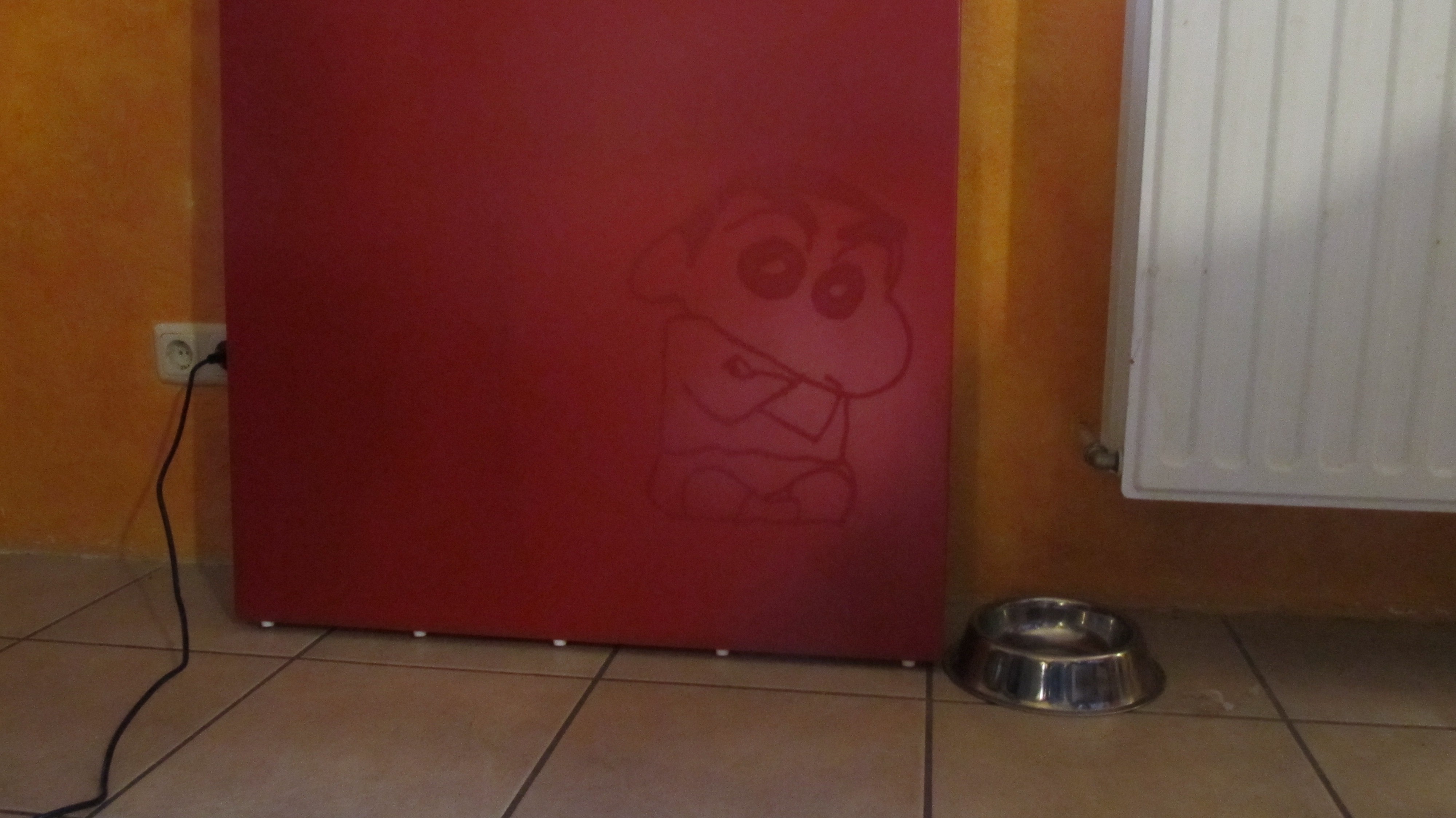
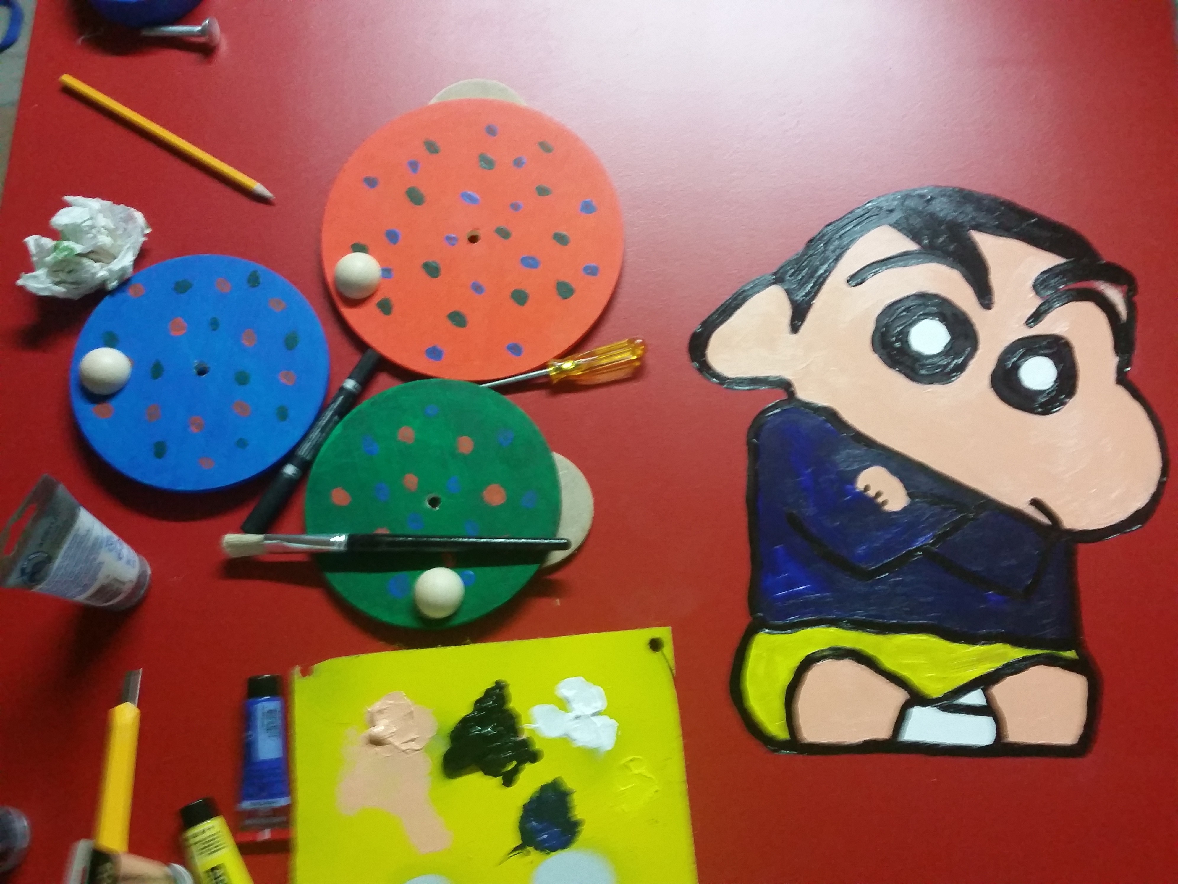
All painted with red paint. I used a small projector to put an Image of Shin Chan on the front. Then I drew the picture and colored it with Acryl colors.
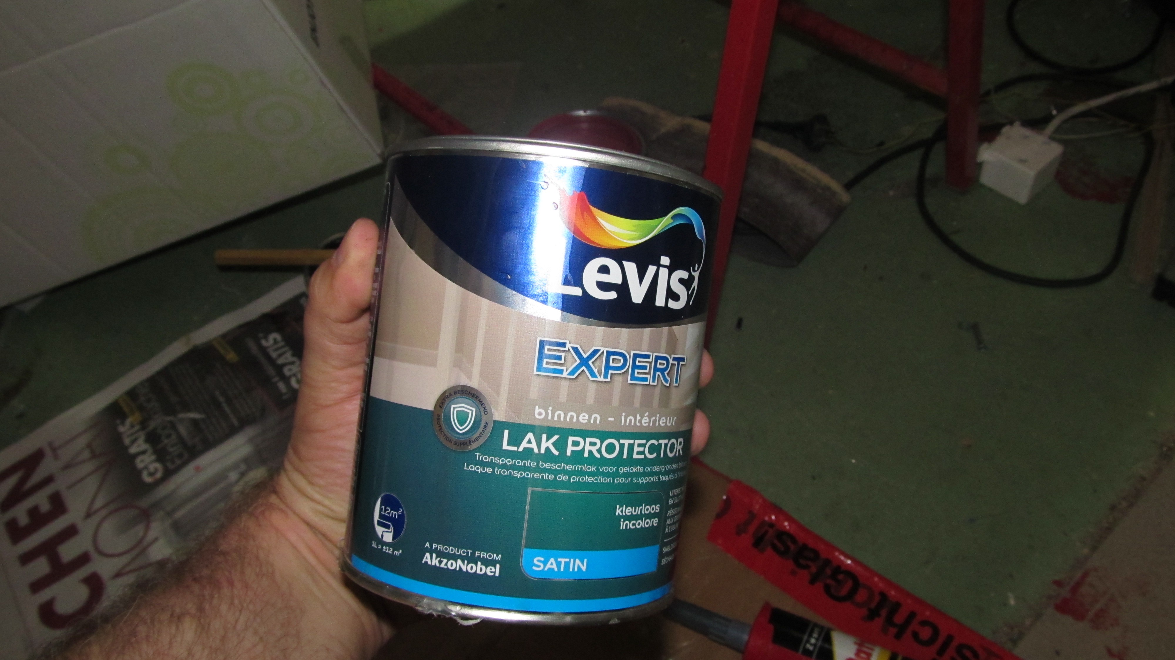
Now 2 layers of transparent protector paint
![]()
-
3Step 3
The Big Piezo Buttons
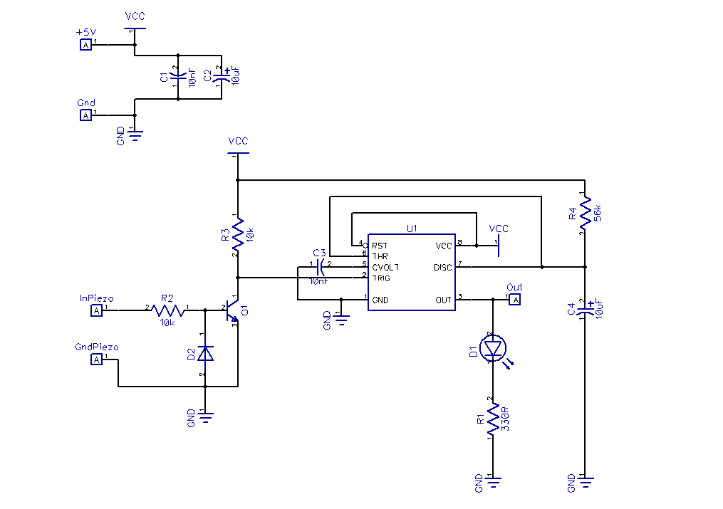
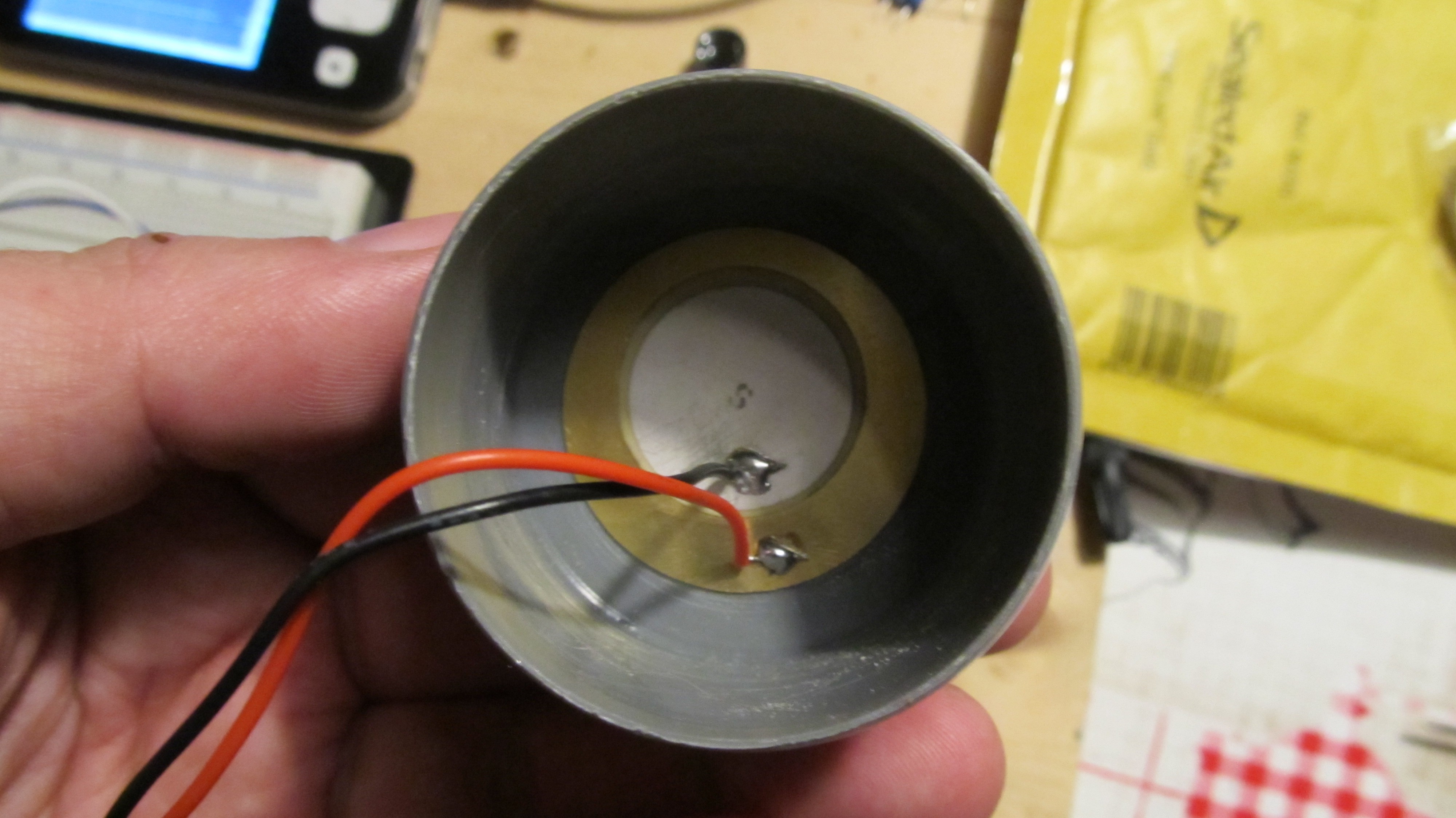
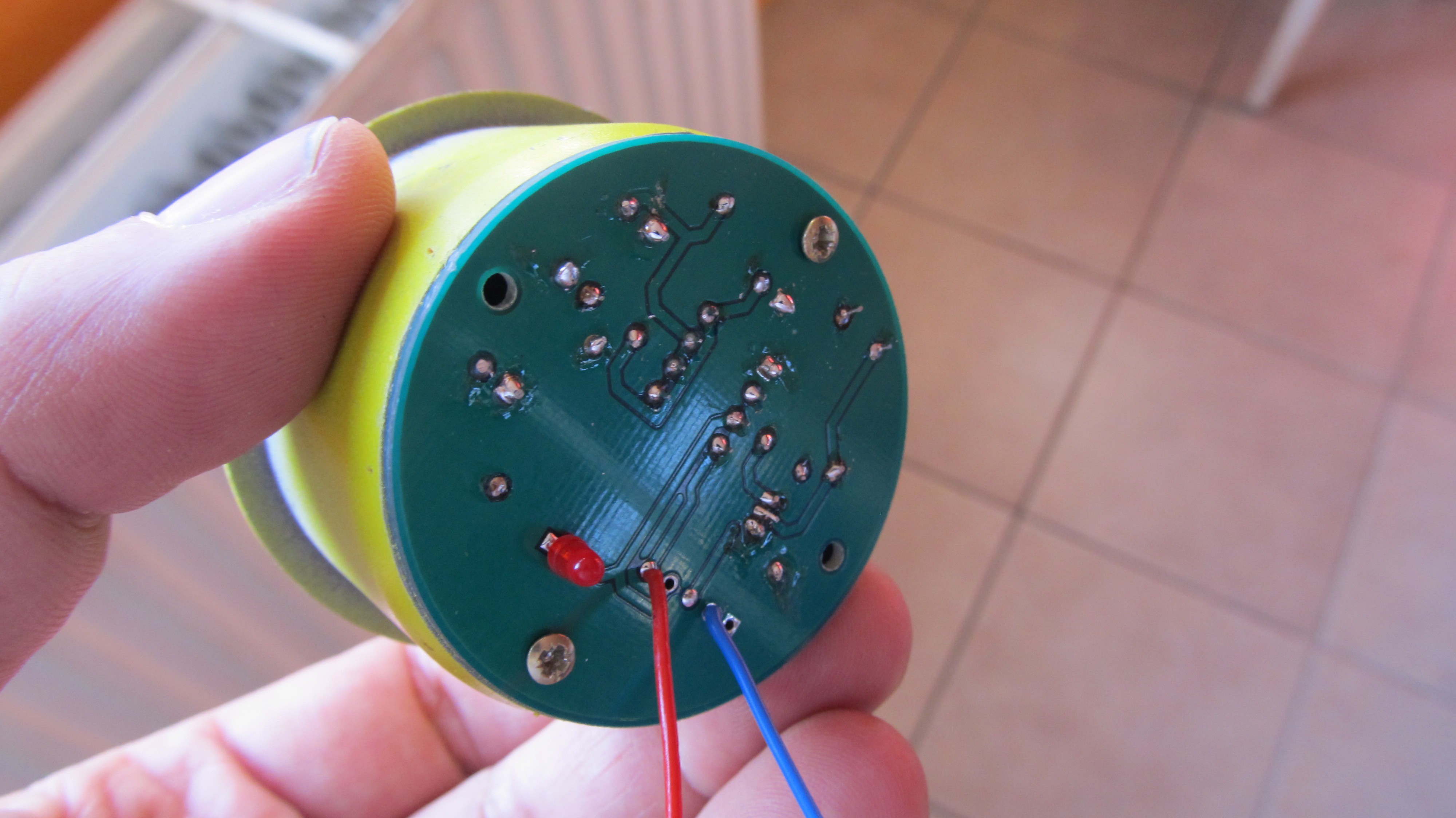
I need a few robust buttons. I could not find buttons in a certain size, so I decided to create my own.When you push or tap the front side of the button, you will get an impulse of +-1sec.The piezo will generated a small impulse, which is amplified by a transistor. A Ne555 in monostable mode gives me a 1sec impulse.
I used a 55mm Pipe Stop End. I sand the piece to remove the irregularities.In the pipe stop end, I glued a 35mm Piezo element inside it with super glue.
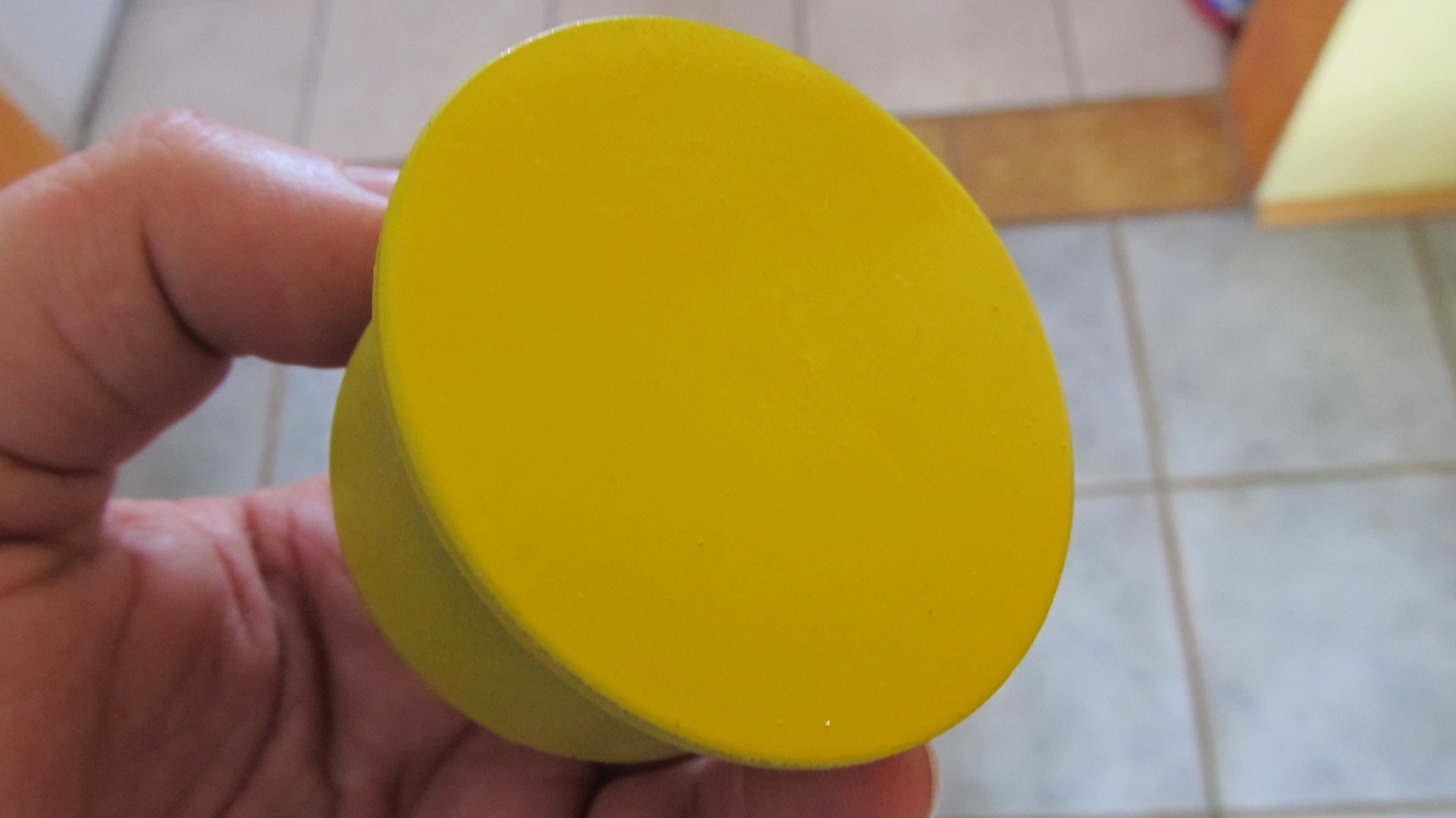
I painted the Button yellow.
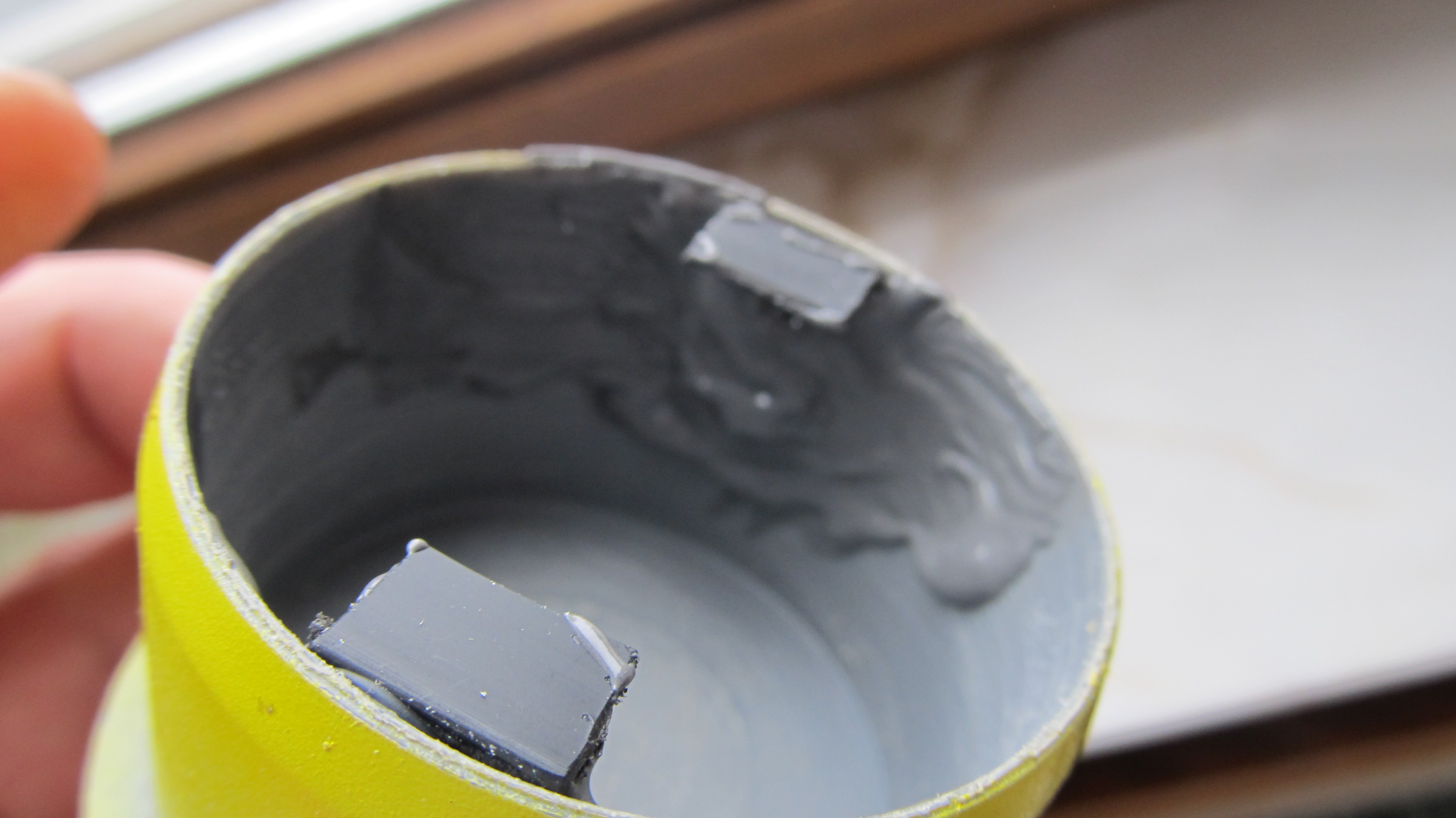
I used a piece of plastic angle and cut 2 small pieces of it. With Hot glue they are kept in place and with epoxy glue they will stay there forever.I drilled 2 small holes in the angels to fix the PCB.
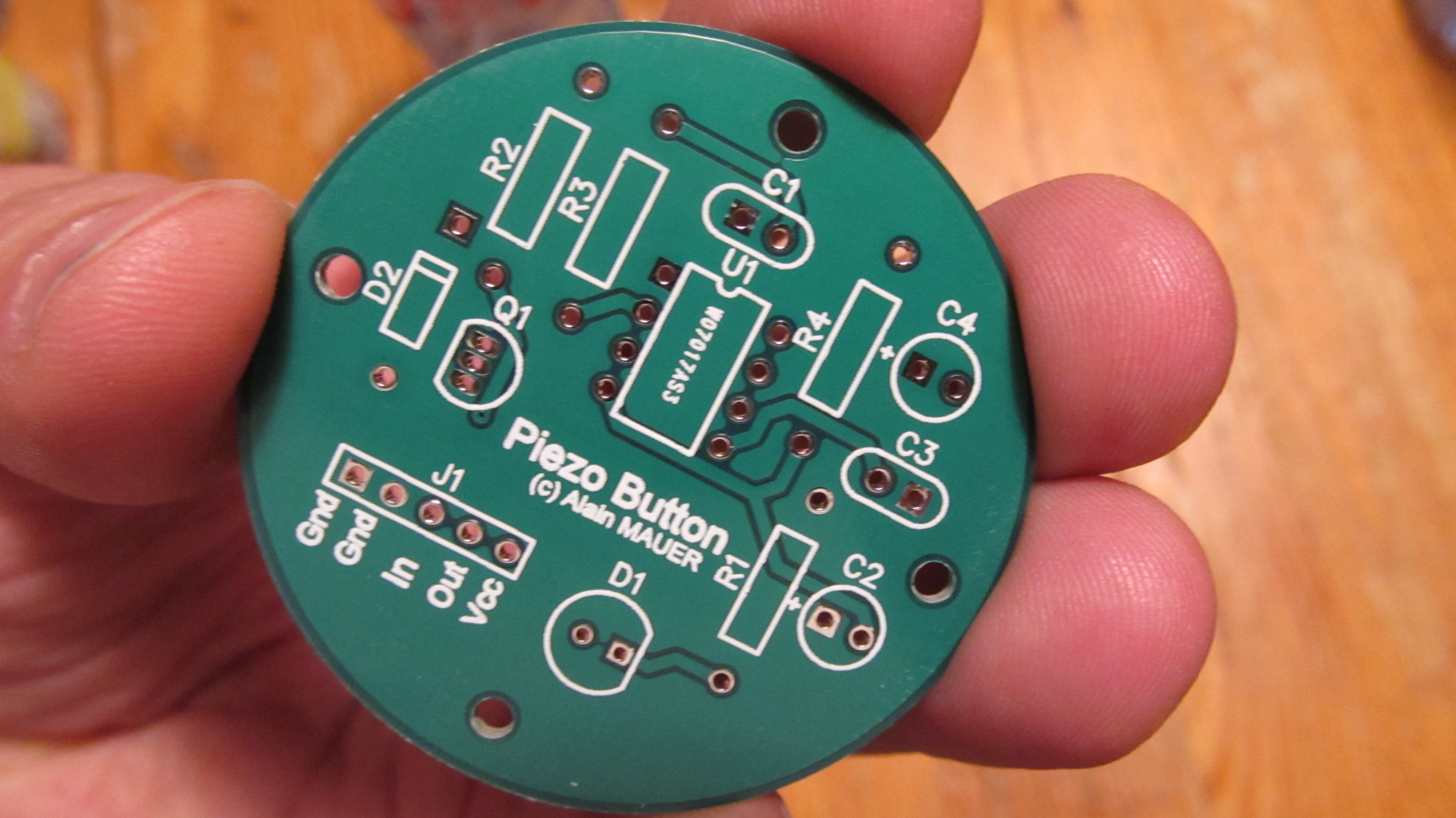
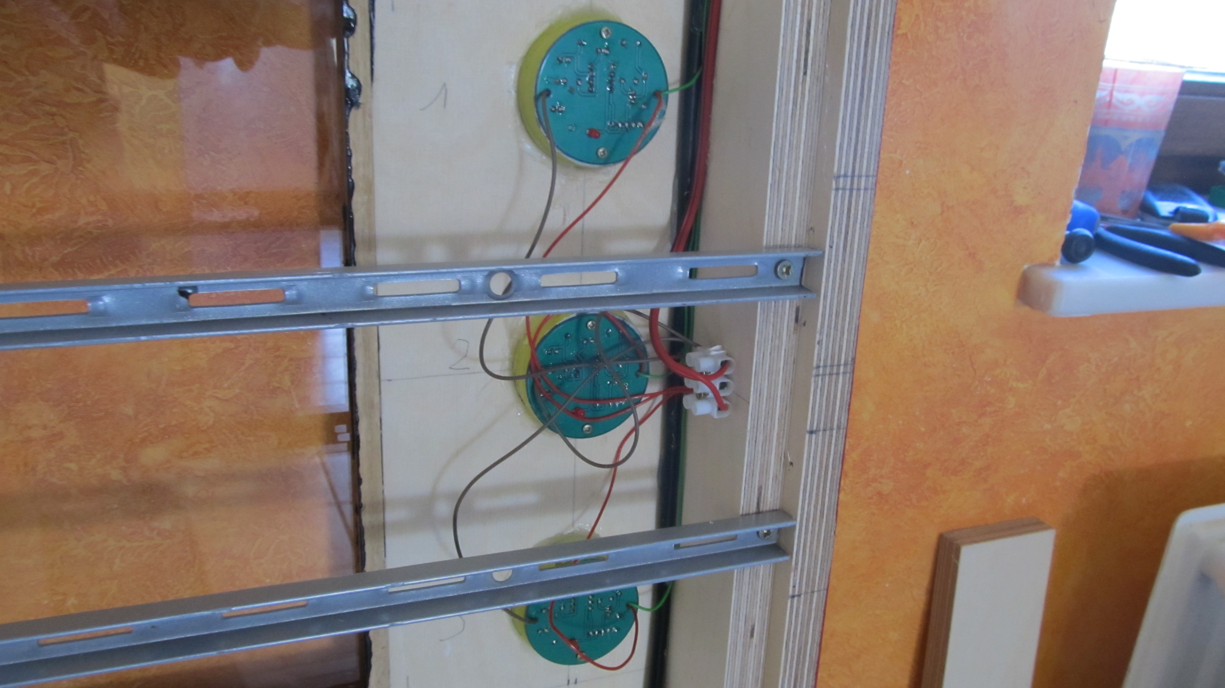
Because I need about 8 buttons, I decided to create a PCB.I used DipTrace for the layout, and I ordered them at http://www.pcbway.com/
-
4Step 4
Tech Inside
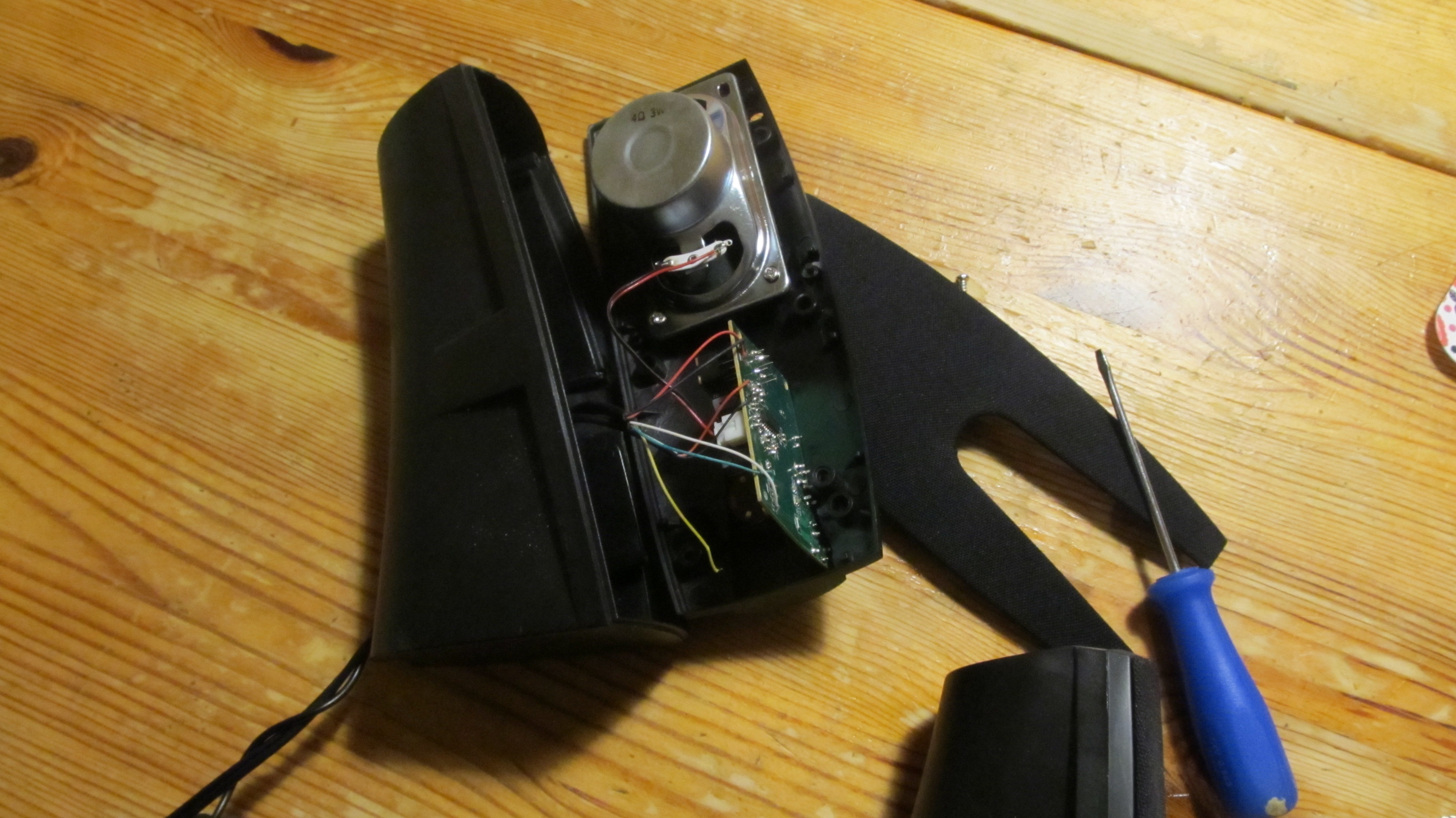
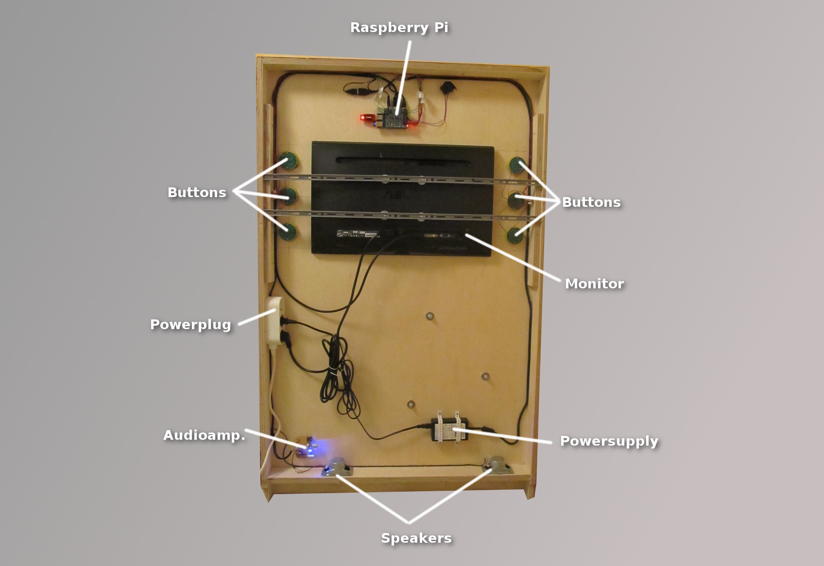
Take apart cheap USB powered Speakers, so you will get an amplifier and 2 Speakers and all the wiring you need.
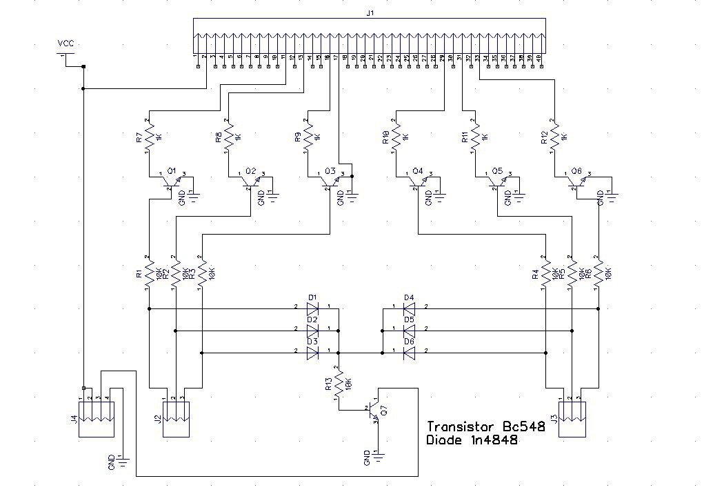
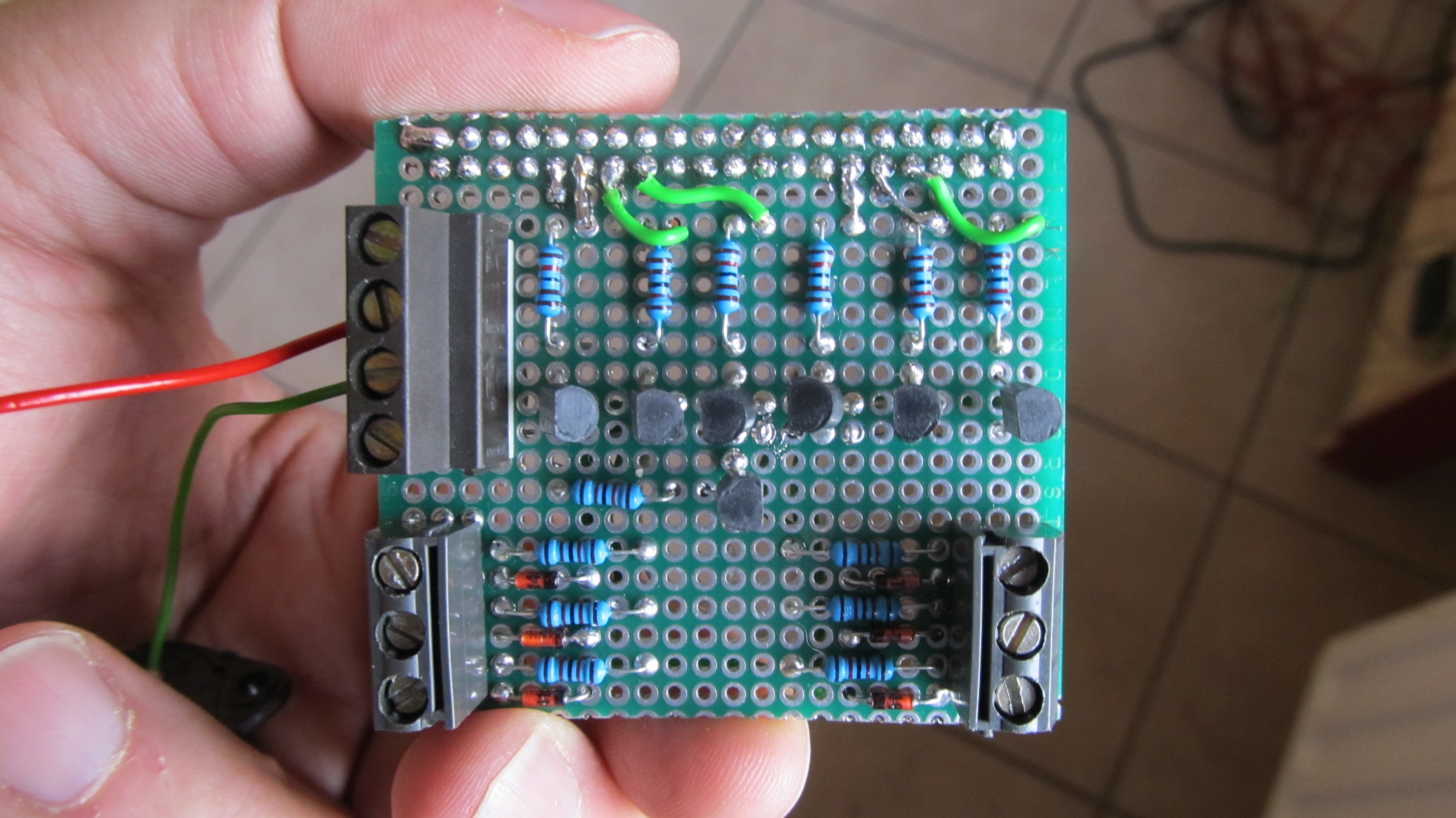
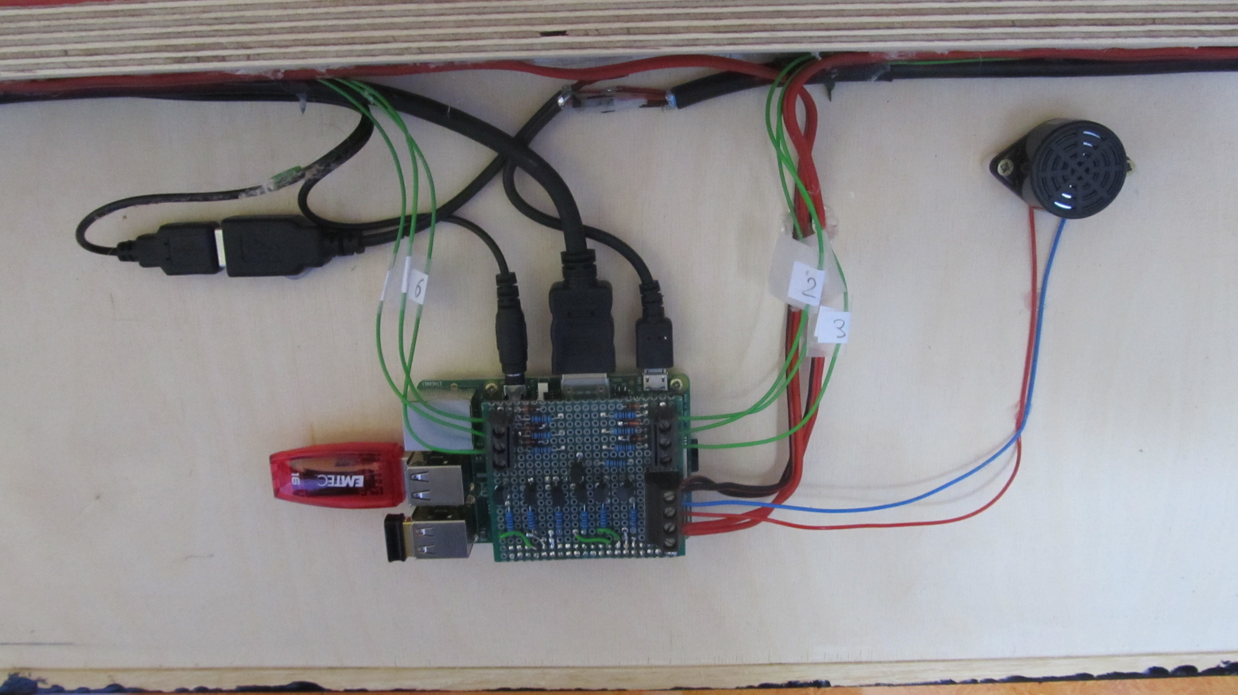
I build an adaptor circuit to connect the 5V buttons to the 3,3V Gpio's of the raspberry. The buttons are connected each to an transistor. The transistor pulls the gpio down to GND.
All inputs are connected over diodes to a buzzer so each time you push a button you have a feedback.
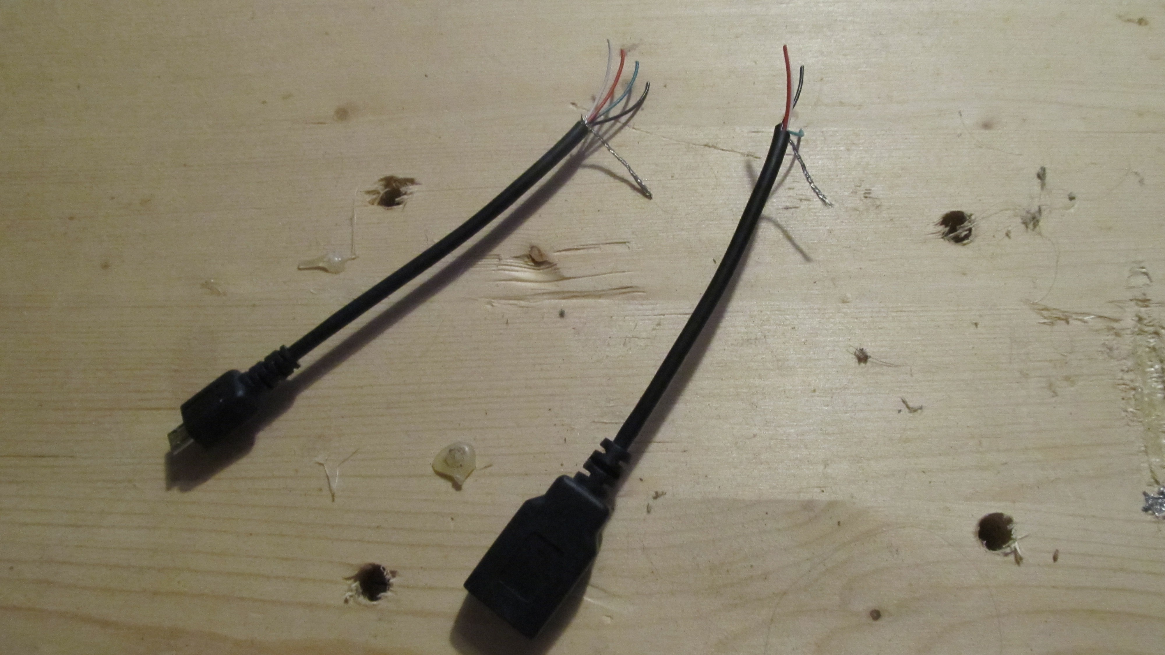
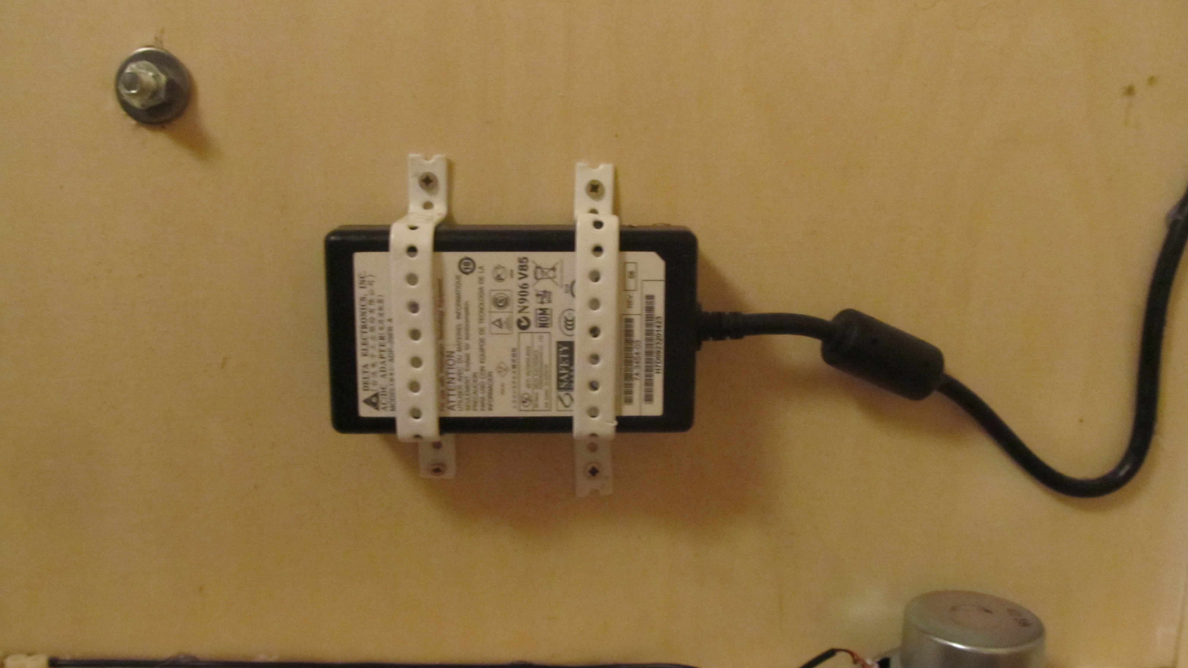
For the power, I used an old 5V 4A power supply. I cut an OGT cable in 2 parts and connected them to the power supply. The micro USB is for the raspberry and the USB port is for the speakers.
All the cables are hot glued in the box
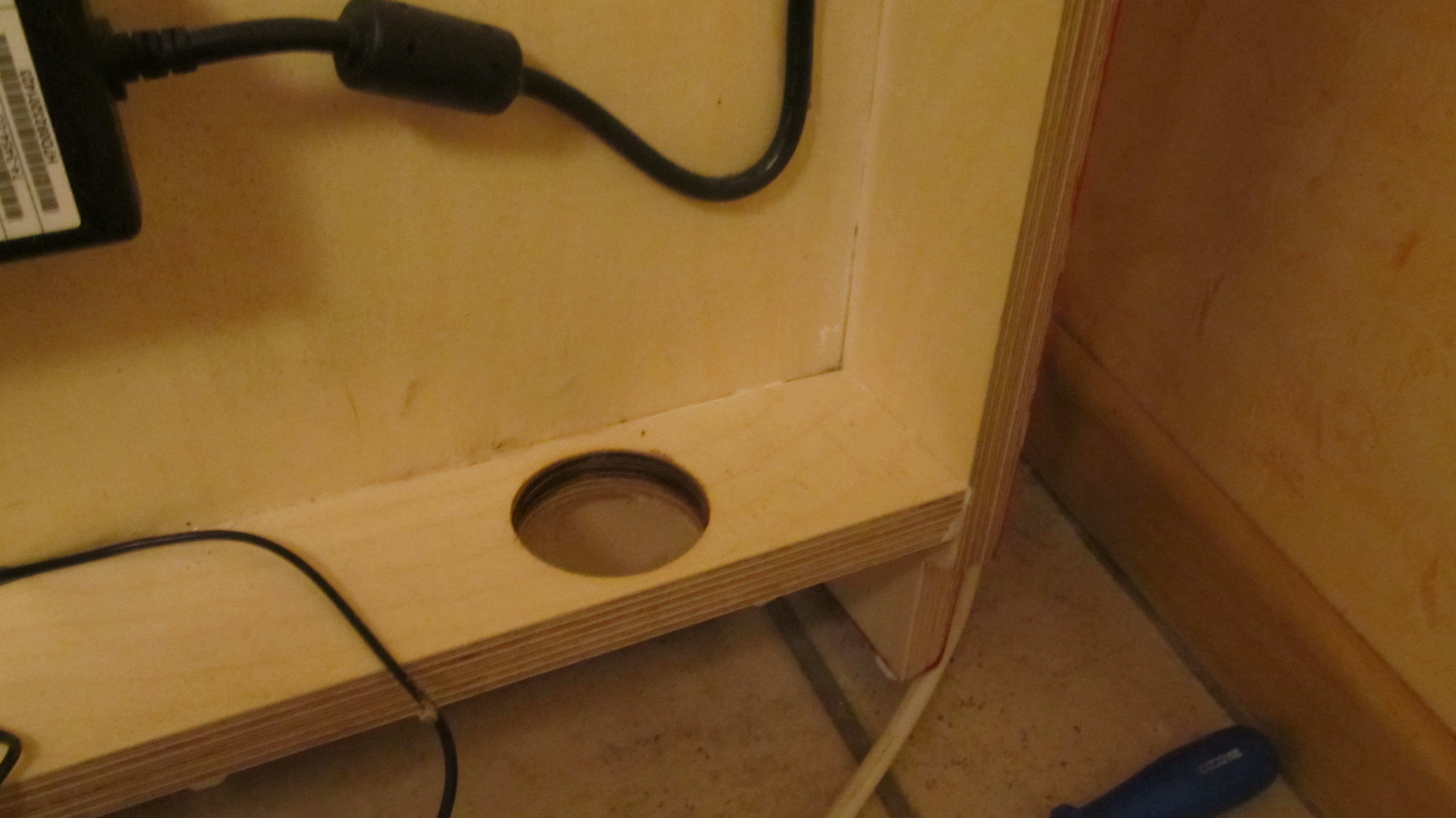
The Speakers are mounted inside, so they can not be destroyed. I drilled 2 holes in the wooden board so that the sound will go downside.
![]()
-
5Step 5
Raspberry Pi Software
I use arch Linux as operating system. It's lightweight and just console based.To playback the videos in the console in overlay mode, I use the omxplayer.
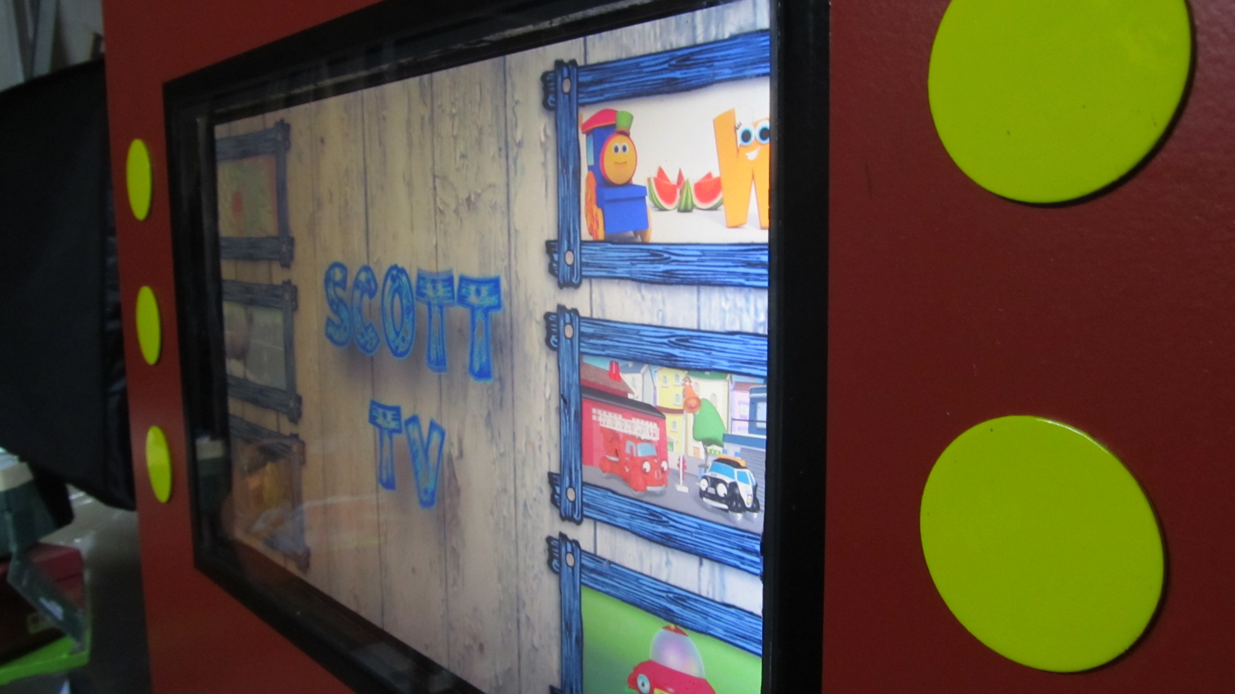
The main-menu is just a one minute looped Video created in Sony Vegas and Gimp for the still images.
The software is written in Python3.x. Then main program "scotttv.py" is starting the menu.m4 and then checks if a button is pushed. If you push a button it stops the menu.mp4 and calls "callvid.py" Here the selected movie (01.mp4 - 06.mp4) is started. When you push now a button, the movie stops and returns to the script "scotttv.py". When no button is pushed and the movie comes to his end, it returns to "scotttv.py" to.
In here the movie menu.mp4 is started again.
My 2 python scripts at Github
-
6Step 6
Last Details For The Enclosure
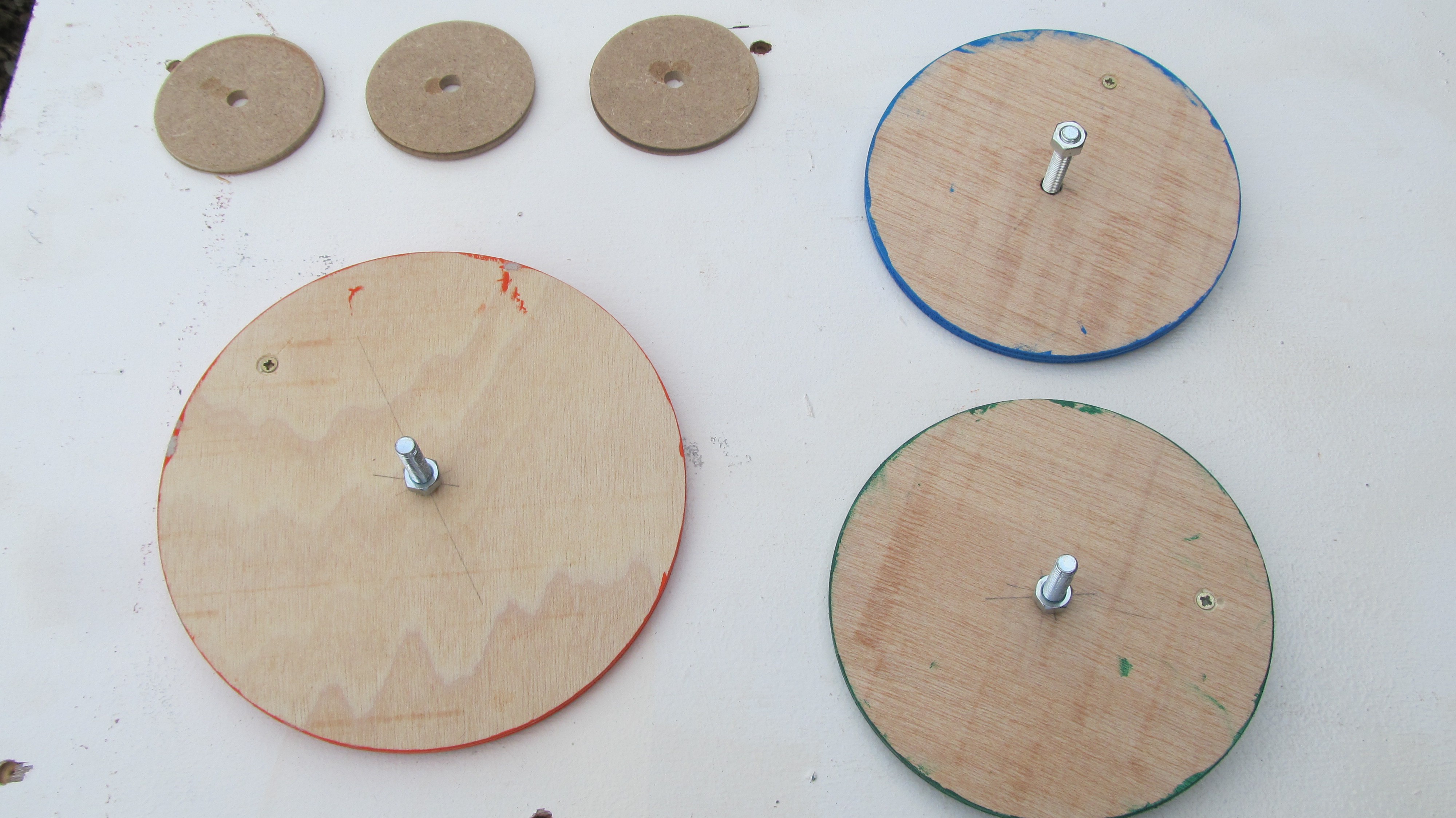
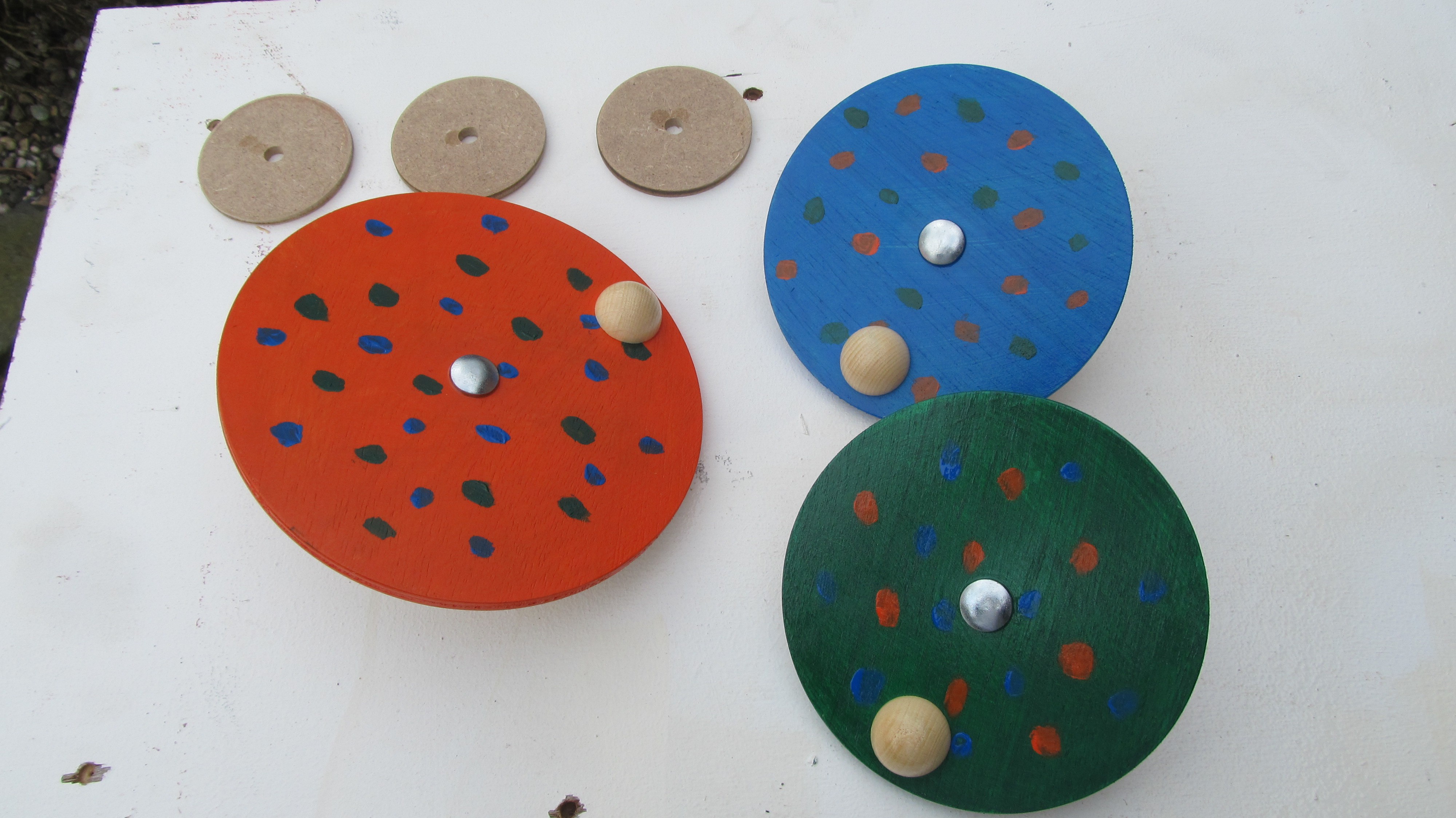
3 Wood discs colored and painted with transparent protection paint.
In the front I drilled 9mm holes. For the moment these discs are just turning around, but I will add some cool features on it later on.
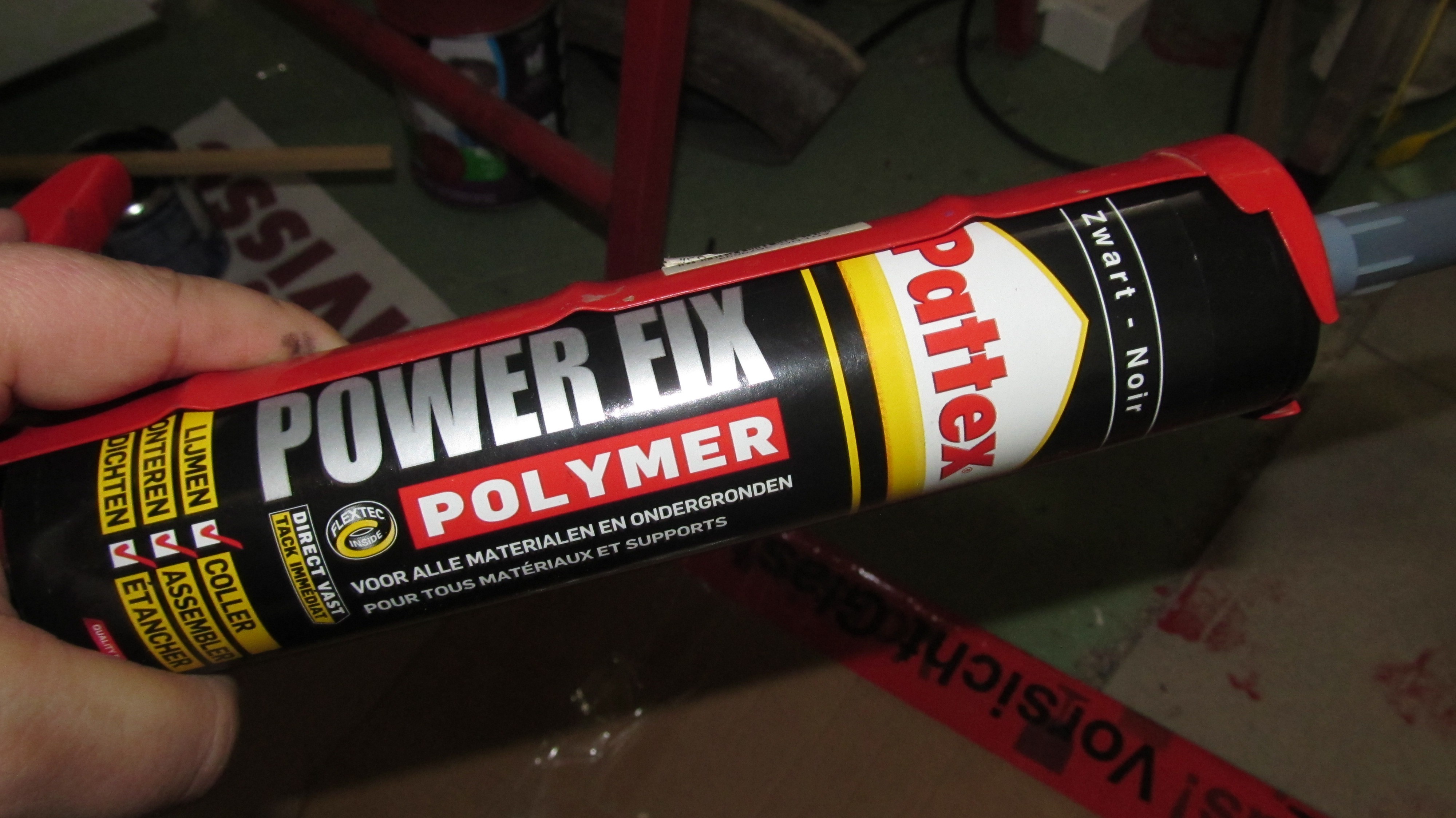
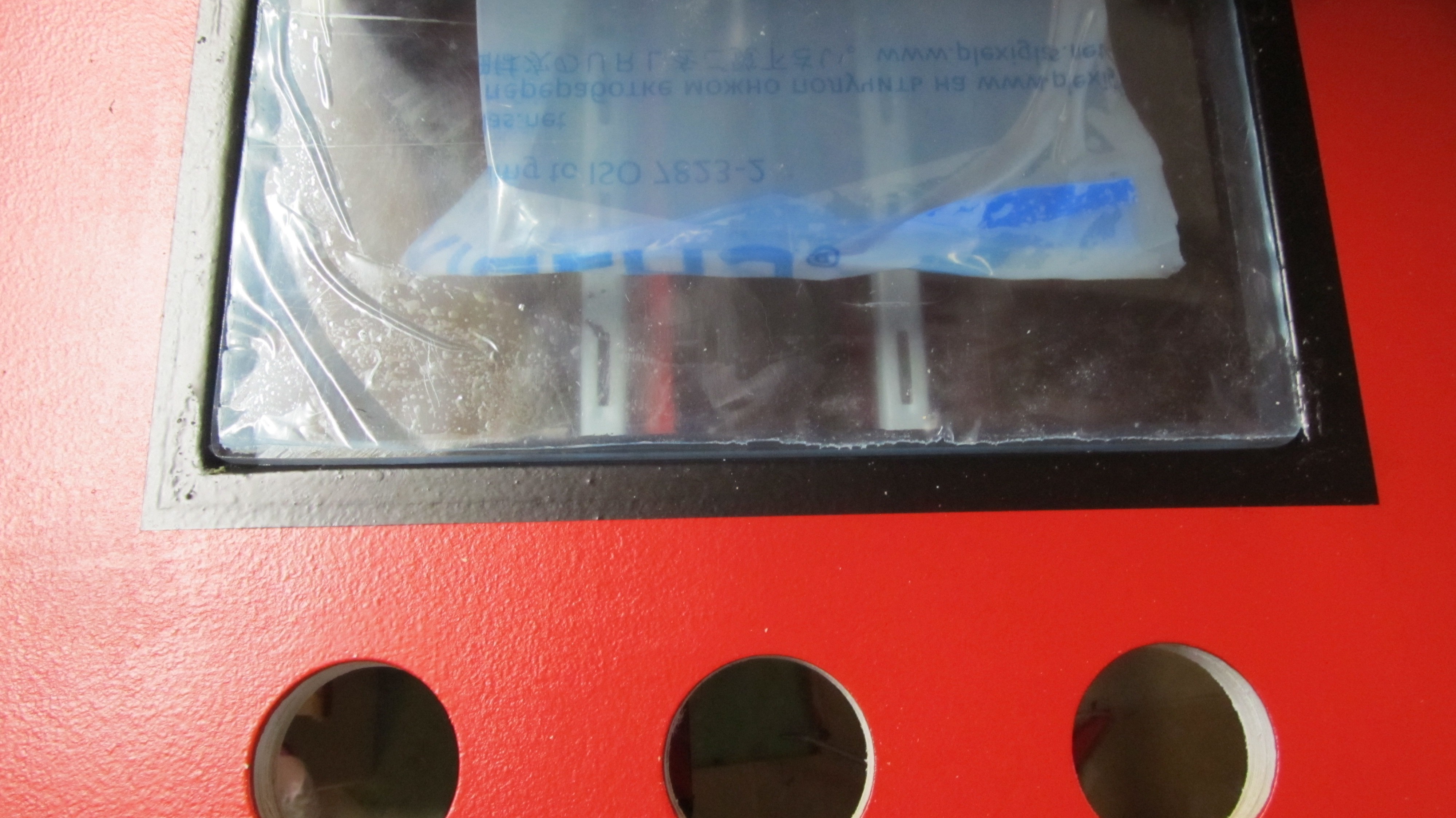
With black power fix, I clued a 8mm Plexiglas sheet for the Screen protection. Let it dry over night with weights on it.
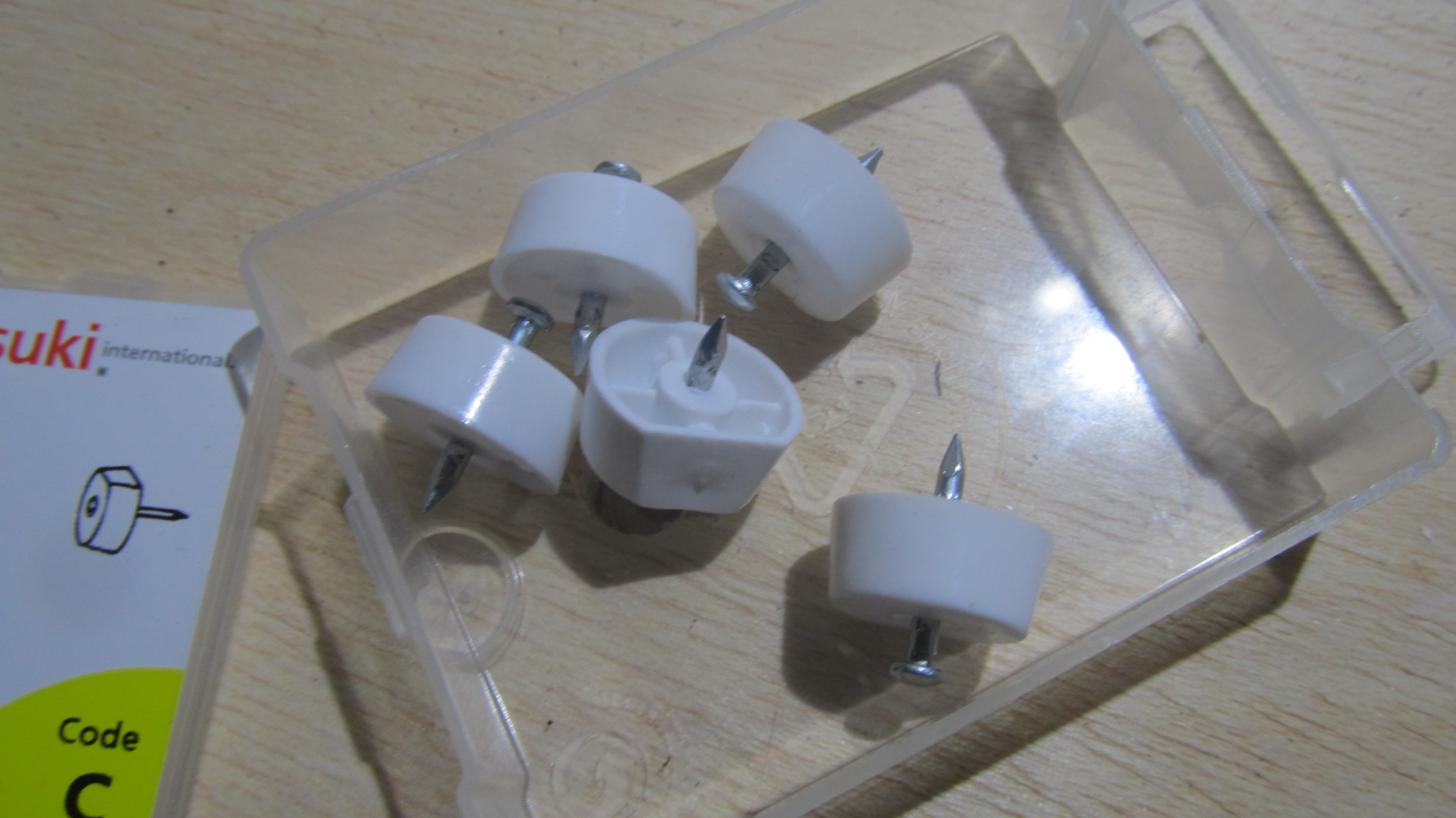
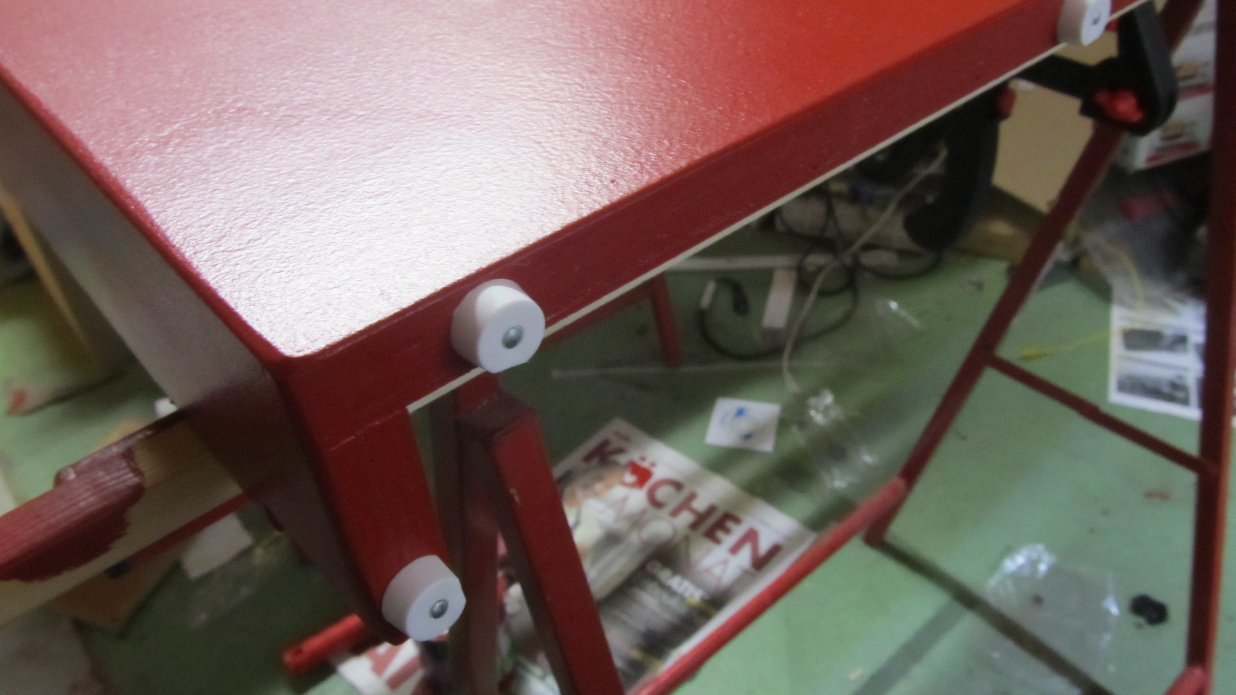
Furniture Nail feets on the bottom of the construction
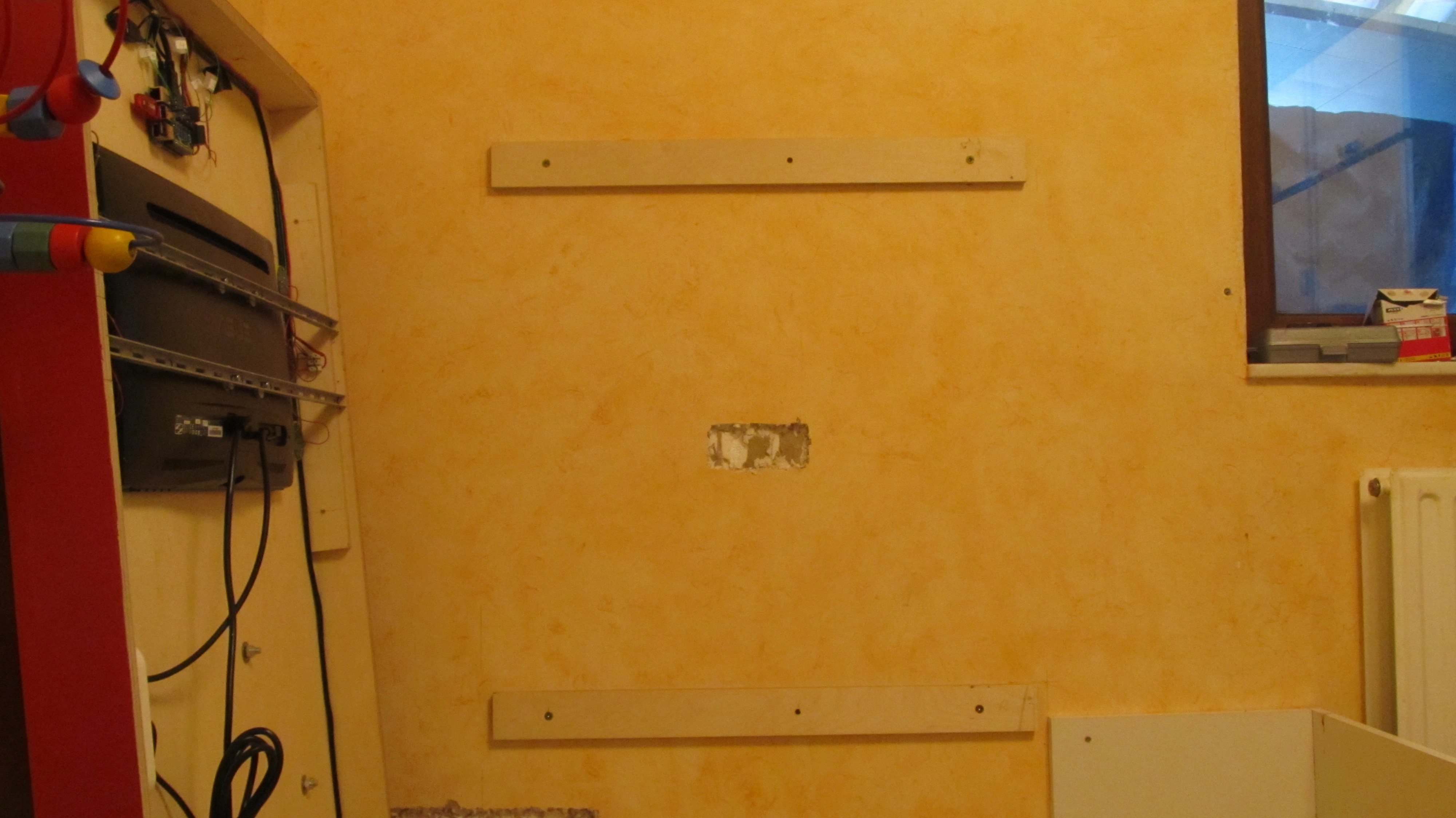
To mount it on the wall, I used 2 wooden boards. Fix them to the wall and screw the ScottTV on it
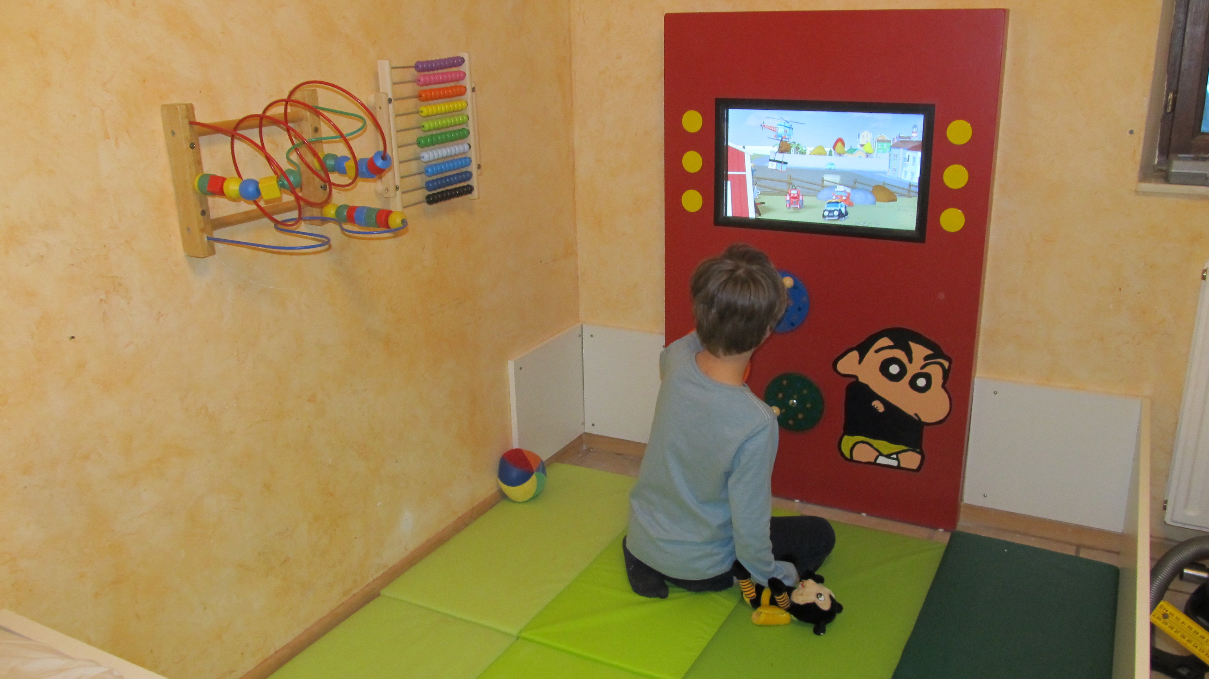
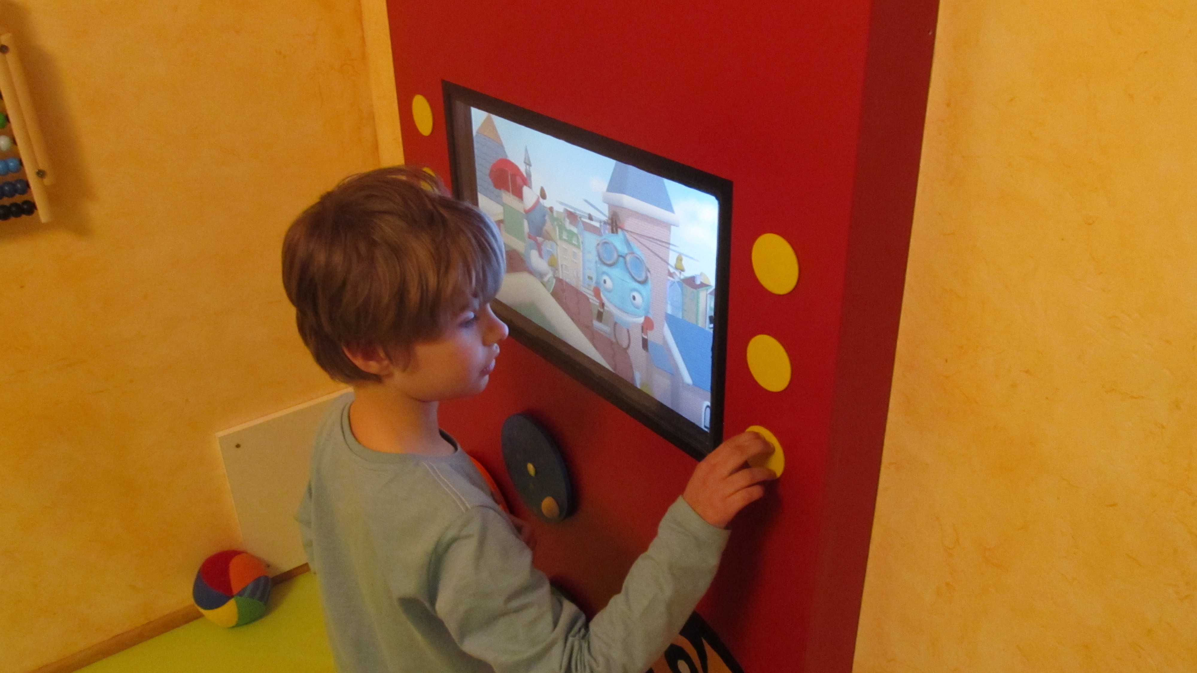
And the best part: Scott loves it.
ScottTV- A Simple MediaPlayer For My Autistic Son
Hi, I needed a simple media player that my son can understand. I could not find a commercial solution, so I built one based on a raspberry
 Alain Mauer





Discussions
Become a Hackaday.io Member
Create an account to leave a comment. Already have an account? Log In.
I would very much like more info on the piezo-buttons. I have a few applications for such a device, and the approach is quite clever. Do you have any plans to publish the board files, or a BOM?
EDIT: Nevermind, just noticed you did an Instructable on the topic! http://www.instructables.com/id/Robust-Big-Piezo-Button/
Are you sure? yes | no