Ted Yapo
-
It's hierarchy all the way down
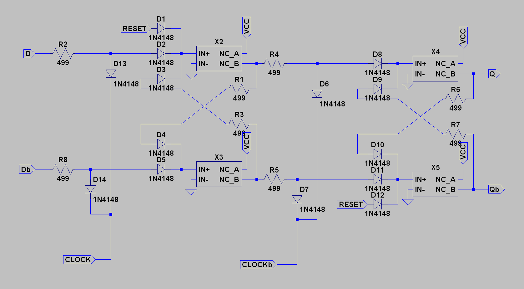
04/06/2018 at 16:49 • 0 commentsI spent a little time today to get a full simulation of one digit going. The box of relays arrived yesterday, but I had to be elsewhere today, so simulation will have to do for now. The counter is made from D-flip flops like this one:
![]()
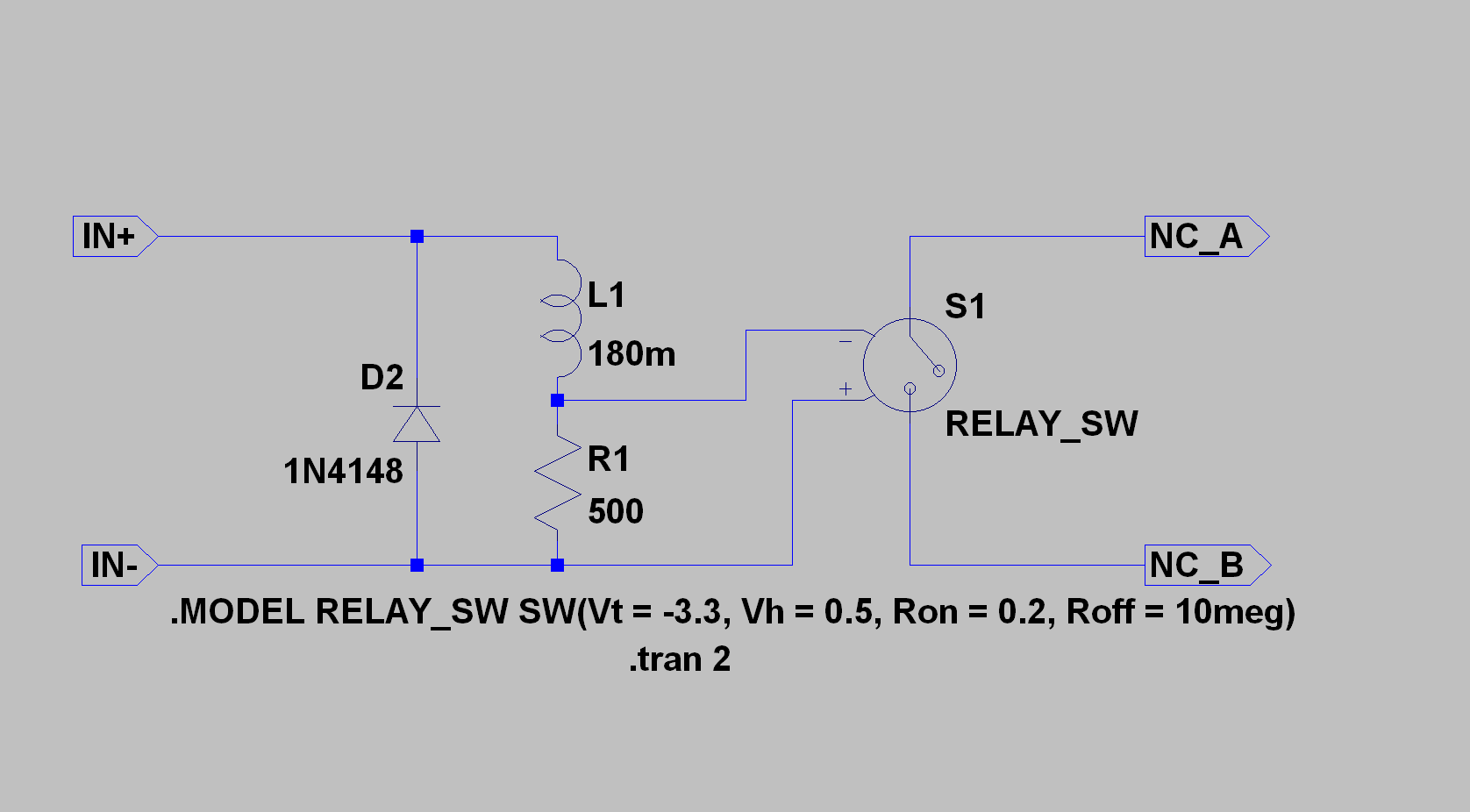
As a two-stage flip-flop, it needs D and Dbar input, and also CLOCK and CLOCKbar as described in the project details. The X{2,3,4,5} components are the relay models. I made a mistake in a previous log that would prevent sequential logic from simulating correctly: the voltage controlled switch should have been across the resistor to simulate the proper delays. Here's the corrected model:
![]()
With this, the flip-flop works as intended.
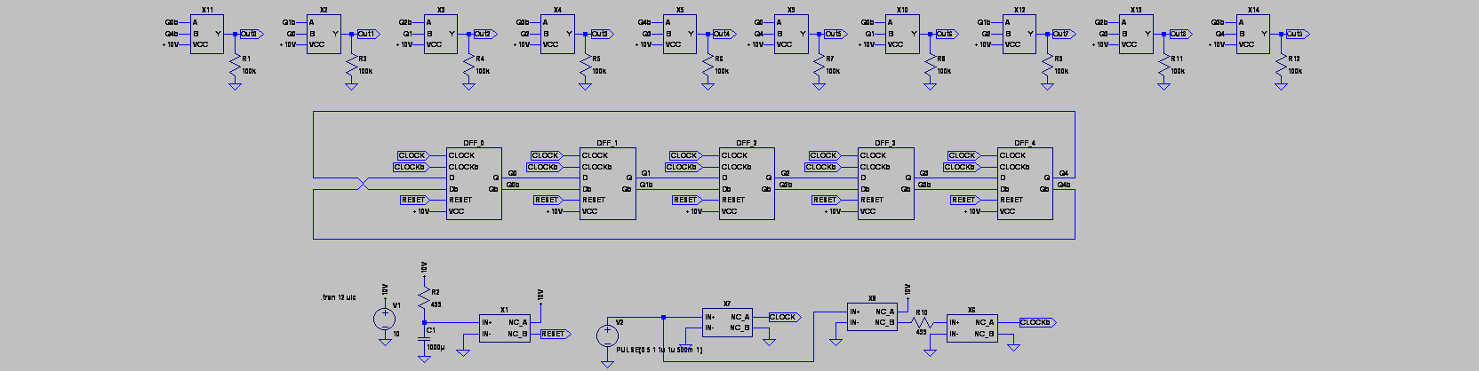
Using the flip-flops, I made a 5-stage Johnson counter which counts modulo-10:
![]()
The five flip-flops are in the middle row. On the bottom are four relays for the power-on reset and the clock drivers. At the top are 10 NOR gates to decode the counter states into (10) 1-hot outputs. These could drive Nixie's directly, or feed to diode ROMs for driving 7-segment displays.
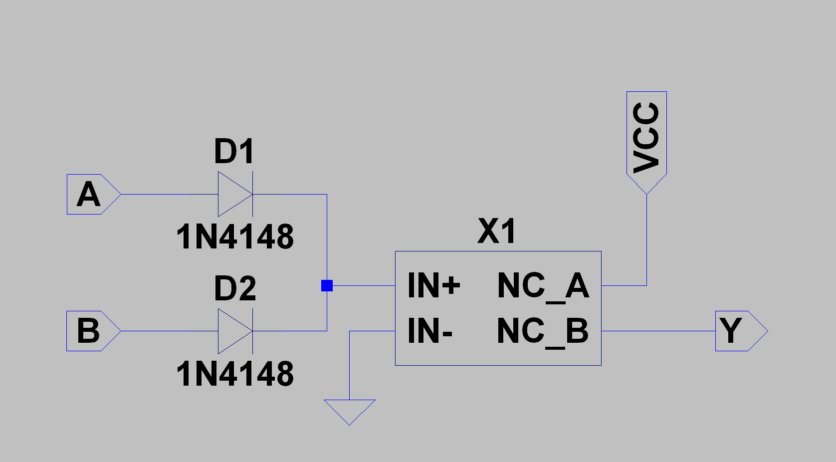
The nor gates look like this:
![]()
where X1 is one of the relays.
The states of the Johnson counter at the Q outputs look like this:
![]()
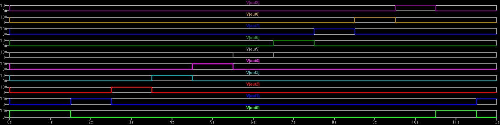
You can see that the counter has 10 states, but they're not much use in this form, so they have to be decoded. That's where the NOR gates come in. The outputs of the NOR gates look like this:
![]()
It's a little difficult to parse, but each of the 10 outputs goes high for one clock cycle in turn. This circuit is basically a CD4017 IC made from relays!
I haven't decided what the display will be yet, although I'm considering making my own stepper-motor-like displays that use coils and magnets to rotate wheels with symbols on them. Think of a 6-wheel slot machine that tells time instead of stealing your paycheck.
This would keep the clock more electro-mechanical, which is kind of what I'm shooting for.
If I do this, I won't need the NOR gates for decoding at all. A stepper-type display could be driven from the clock phases directly. The counters would only be needed to divide the clocks for the next stage. A big benefit of this design is that the seconds one digit doesn't need a counter at all, so the clock lifetime should be extended.
-
Simulating Relays
04/03/2018 at 17:37 • 4 commentsMy relays aren't here yet, and I'm bummed out about it, so I decided to simulate one so I could design some of the more analog parts of the clock, like the power-on reset circuit.
![]()
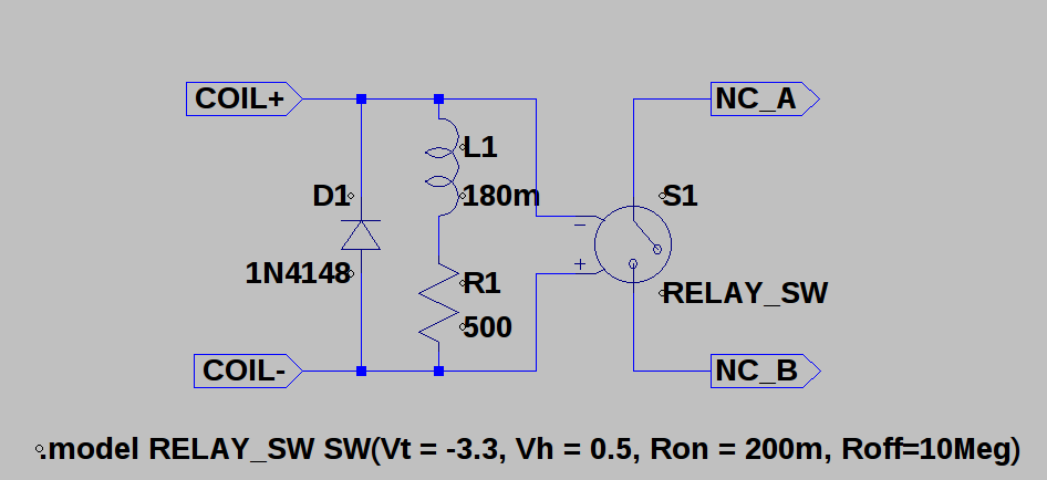
This is what I came up with. The coil resistance is specified by the manufacturer, as are the pull-in and drop-out voltages (modeled here as a threshold and hysteresis value). What they don't tell you is the coil inductance. I guessed at a value based on the pull-in and dropout times and the voltage thresholds. With a 180m inductor, the switch in this model has similar timing to the published relay specs.
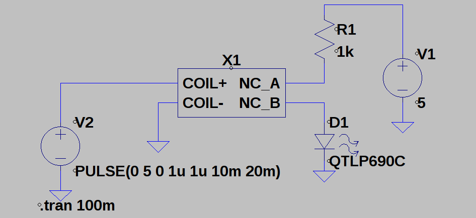
To get a normally-closed output, I reversed the connections to the voltage-controlled switch component and used a negative threshold voltage. This whole circuit can be encapsulated in an LTspice symbol, shown here switching an LED:
![]()
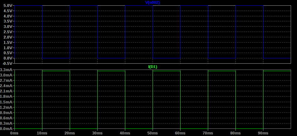
When the input is high, the switch is off, and vice versa:
![]()
Which isn't really that impressive, I guess, but that's not really why I made the model.
Slightly more interesting is the power-on reset circuit:
![]()
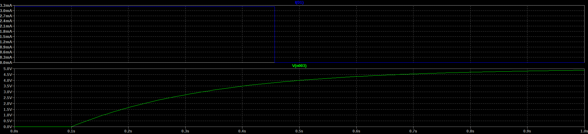
The supply starts at 0V and comes up to 10V at 100ms. R2 charges C1 slowly, delaying the opening of the relay contacts. With these values, the delay is about 350ms:
![]()
You can see the linear ramp (bottom; green) and the LED current (top; blue). The LED here represents the reset line for all the flip-flops. They'll be held in reset for those initial 350ms, ensuring they start in a known and stable state.
Is this a perfect simulation? Probably not - some values will need to be tweaked when I move to the real hardware, but I can get a qualitative feel for how things will work.
Oh, and here's another one, an RC relaxation oscillator:
![]()
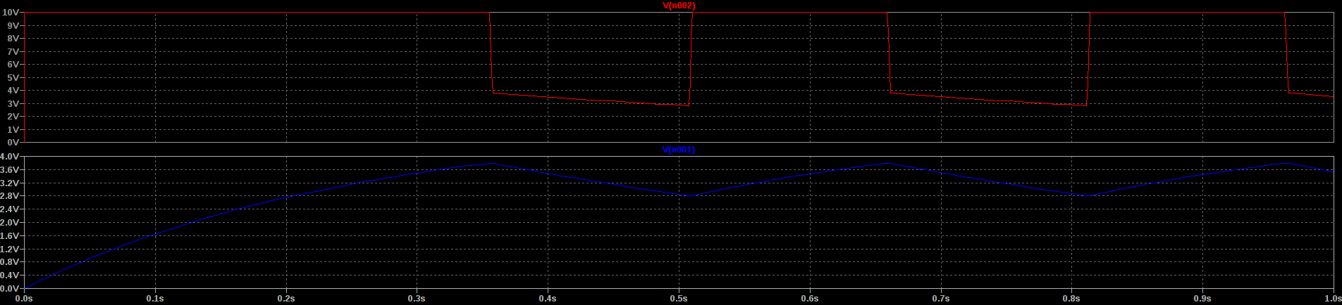
It's the same thing you might see made with a Schmitt-trigger inverter, and relies on the hysteresis of the relay to switch on an off, charging and discharging the capacitor. Here's the output:
![]()
The bottom trace (blue) is the voltage on the capacitor charging and discharging, with the output shown in the top trace in red. It oscillates at about 3Hz with these component values. Is it stable enough to keep time? Absolutely not. Probably not, anyway.
-
Relay Lifetime: 7 days - 190 years
03/30/2018 at 04:53 • 3 commentsThe SE1B05AXJ relays I will be using have a rated lifetime of 6x10^5 actuations at the rated load (500 mA), or 10^8 at 10 uA. Since the coils are 5V/500 Ohm, they consume 10 mA. This implies a maximum fan-out of 50 for the logic gates, which is an interesting side note, but doesn't help with the lifetime calculations.
Assuming worst case load, 6x10^5 is the number of seconds in 7 days. That isn't a very long lifetime for a clock. Using the 10^8 figure (which is unrealistic), the figure is 3 years. Still not great, but I could presumably swap in fresh relays.
What if I just built an HH:MM version? Then, the 6x10^5 actuations turns into 416 days, and the 10^8 into 190 years. The truth is somewhere in between, but this sounds much better.
I think for now, I'll build an HH:MM version. I can add a seconds stage later.