Connector
If you decide to desolder the original camera connector, feel free to tear the shield pins off. However, it's somewhat better if you leave them on - less chance of ripping the other pads off.
Otherwise, make sure you're leaving at least 5cm of wires for your experimentation. Also, keep in mind that the thin wires usually encountered in camera connectors are easy to tear out of the connector - make sure you don't pull on the wires!
Pinout
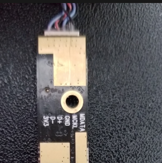
Some cameras show their pinout on the back silkscreen:

If you're not so lucky, you will have to find the proper pins one-by-one. Here's how:
First, find and solder the GND pin. The gold-plated rings around the mounting holes on the camera PCB are connected to GND - so take a multimeter. By the way, the connector's shield pins are often NOT connected to GND.
Then, look for VCC - find the nearest capacitor to the connector, then find the GND side of this capacitor - the other side is likely to be connected to VCC. There are also other capacitors on the camera board, that's why I'm saying to look at the closest ones. If you can't find the VCC pin, just find the D+/D- pins, the one pin that's not data or ground-connected is exceedingly likely to be VCC.
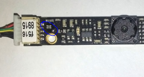
D+/D- wires are often twisted, not always, but when they are, it's a dead giveaway. D+/D- pins are usually connected to a small filter on the PCB:

Just use your multimeter to find which pins of the connector are connected to this filter, these will be your D+ and D- pins. Also, if you end up tearing off the D+/D- pads, this filter is where you'll be able to take the missing signals from (though you will need to use 0.1mm magnet wire and a fine-tip soldering iron, anything else will just cause more problems).
It's OK if you mix D+ and D- pins up, the camera just won't work - so if it doesn't work once you've soldered all the wires, try swapping the D+ and D- wires and then plugging the camera in again.
On high-end laptop cameras, there can be a fifth wire (one that's not involved with some kind of microphone) that is not connected to either VCC or GND. Try leaving it alone, but if the camera doesn't enumerate and doesn't cause USB errors either, try touching it to VCC or GND, it might be a "camera enable" pin.
Voltage
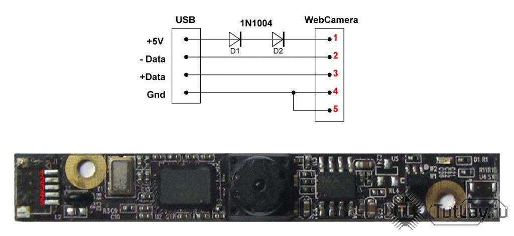
Laptop cameras work better with 3.3V, as they're designed for 3.3V operation inside the laptop. While it's tempting to feed it 5V from the USB connector (and many tutorials on the Internet suggest that), your camera is likely to either overheat or burn up. The best option is to add a small 5V-3.3V regulator (or use 3.3V directly if you're connecting your camera to a Pi), but if your budget is limited or you can't find a regulator, two diodes (regular, not Schottky ones) will also work:

If you use diodes, they have to have approximately 0.7V voltage drop. Diodes like 1N4007 (the 1N400* family) or 1N4148 will work! Schottky diodes (like 1N5819 and SS14) have a lower voltage drop and you risk burning a 3.3V camera if you use two of those, sadly.
Software (Linux)
Debugging
dmesg | tail for reading the last 10 kernel events, in case you've fucked up, it will mention something like usb 1-1: device descriptor read/64 . I recommend running dmesg -Hw & , that will make dmesg run in background and print USB events (among others) as they appear.
If your USB port stops working altogether after an experimentally plugged USB device and dmesg on your Raspberry Pi says this :
usb usb1-port1: attempt power cycle
Then disconnect the offending device and use this command:
echo 0 > /sys/devices/platform/soc/20980000.usb/buspower; sleep 1; echo 1 > /sys/devices/platform/soc/20980000.usb/buspower
It will reset your USB port. However, if you plug the device again and it will be faulty, your port might error out again. Also, this command might not work on full-sized Raspberry Pi that have 2 or more USB ports - this command crashed the Pi3 I tried it on. However, it's also possible the Pi3 USB port will not be susceptible to this problem.
Camera info
Isusb to list the USB devices connected, show the USB VID/PID and the USB device name (the name is not necessarily useful and is taken from a database that's stored inside your Linux distribution). There are all kinds of lsusb options to get more info, i.e. about specific devices - use man lsusb to learn about these.
v4l2-ctl --all can be used to show general-purpose information about a camera
v4l2-ctl --list-formats-ext can be used to show resolutions and formats supported by the camera (including the hardware-accelerated outputs)
UPD on pinout decyphering woes from @Joel :
>>> (Joel) a strange thing I noticed. on two of the HP cameras, the ground was not grounded on the shield or ground holes
>>> just thought that was a bit strange and may want to add it in the post
>>> also the red/black wires were reversed
<<< (me) true. I see that sometimes with the shield, never with the holes. thank you!
[...]
<<< what was the method you used to determine the right polarity in the end?
>>> actually I was wrong, one of the HP cameras was grounded on the holes. so I could use that to tell that the polarity was revered from that. I then had a newer HP camera with the same wire colours, but no wires where grounded on the holes, so took a chance with the reversed polarity and it worked
 Arya
Arya
Discussions
Become a Hackaday.io Member
Create an account to leave a comment. Already have an account? Log In.
You should add a section on what to do if you laptop camera only has three wires like mine :P
: /
Are you sure? yes | no
Ooh that is interesting! Can you share some pictures? Perhaps, join the chatroom ( https://hackaday.io/messages/room/280686 , or the "Public Chat" button on the main project page ), send them and @ me so I get a notification?
Are you sure? yes | no
@paulhoets oh, I know that, and mentioned as much in the article, Ctrl+F "two diodes"! However, if I reuse something, I do my best to ensure it will work, a 20-pack of 3.3V regulators is $1 on eBay, and capacitors are dime a dozen - literally. Wouldn't like to have someone use Schottky diodes and burn a camera that they've invested effort into reverse-engineering!
Are you sure? yes | no
oh, and added a bit of info on diodes that are usable for this, thank you for inadvertently pointing out a gap.
Are you sure? yes | no
Sorry for this noob question but other then overheating of the cam can this cause issues to a laptop.
Are you sure? yes | no
It's such a shame I didn't see this question earlier somehow =( Well, doesn't help that I only understand your question partially =D This guide assumes that you're taking a camera out of the laptop. It should be safe for the laptop to take a camera out of it, if it's working, it should stay working anyway. This guide is also written to decrease possible damage to a camera you're reusing, as much as that's possible.
Are you sure? yes | no
In the first picture with the pinout printed, I have a similar camera module, but what is needed to use it? Does it require 3.3 v instead of 5? What is MDATA and MCKL?
Are you sure? yes | no
5V will likely burn it - I've seen cameras that work from 5V but most work from 3.3V, 5V cameras are rare. MCLK and MDATA are clock and data lines for an onboard digital-output microphone - it uses either PDM or I2S and should be reusable with a Raspberry Pi and a lot of PDM/I2S wizardry.
Are you sure? yes | no
So, you need 1) a USB cable 2) a 5V=>3.3V regulator, i.e. 1117-3.3.
Are you sure? yes | no
Um, no. That's the purpose of the 2x diodes - it drops the voltage to something close enough to 3V3 for everything to be working fine.
Are you sure? yes | no