Arya
Arya-
Known camera pinouts
04/30/2020 at 00:54 • 0 commentsThis is a worklog to help make corellations between camera cable colors and pinouts - or learn that there's nothing useful you can learn from these. For pinout deciphering guidelines, see here.
From @Joel :
HP DC01901LA (Webcam-101) (older webcam) Twisted yellow D+ Twisted orange D- Green 3v3 Red Gnd (brown, black not used) That is the same pinout for the newer HP 708230 -
Successfully reused cameras (+ not working cameras)
05/29/2019 at 18:17 • 0 commentsHere's a list of lsusb entries with cameras that have successfully been reused:
- ID 090c:37a9 Silicon Motion, Inc. - Taiwan (formerly Feiya Technology Corp.)
- Lenovo EasyCamera, YUYV 4:2:2, 640x480 20fps, up to 1280x1024 7.5fps (likely interpolated)
- ID 064e:a219 Suyin Corp. 1.3M WebCam (notebook emachines E730, Acer sub-brand)
- eMachines E730 camera, YUYV 4:2:2, 640x480 30fps, up to 1280x1024 7.5fps (likely interpolated)
- ID 090c:37a2 Silicon Motion, Inc. - Taiwan (formerly Feiya Technology Corp.)
- HP Webcam 101, YUYV 4:2:2, 640x480 24fps
- ID 04f2:b064 Chicony Electronics Co., Ltd CNA7137 Integrated Webcam
- CNA7137: Chicony USB 2.0 Camera, YUYV 4:2:2, 640x480 30fps, up to 1280x1024 7.5fps (likely interpolated)
- ID eb1a:2761 eMPIA Technology, Inc. EeePC 701 integrated Webcam
- UVC Camera, YUYV/UYVY 4:2:2, 640x480 30fps
- From an EEE PC 701
- Silkscreen says that requires 3.9V but it seems to work on 3.3V
- ID 04f2:b015 Chicony Electronics Co., Ltd VGA 24fps UVC Webcam
- HP Webcam, YUYV 4:2:2, 640x480 24fps
---------- more ----------- ID 04f2:b053 Chicony Electronics Co., Ltd
- Chicony CKA7216 HP Webcam (2 MP), YUYV 4:2:2, 640x480 30fps, up to 1600x1200 5fps (likely interpolated)
- From a HP Elitebook 8530p (a laptop on the expensive side), so, the camera is quite fancy
- Fifth (orange) wire needs to be connected to VCC for the camera to show up (connects to pin between VCC and GND)
- Has some kind of focus adjustment! The focus is available through v4l2-ctl, haven't checked if it's manual-only or also auto-focuses.
- ID 04f2:b3b2 Chicony Electronics Co., Ltd
- TOSHIBA Web Camera - FHD: TOSHI, YUYV 4:2:2, MJPG, 640x480 30fps, up to 1920x1080 30fps
Here are some cameras that don't work in one way or another (Raspberry Pi Zero, direct connection, dwc-otg driver):
Does not create a /dev/video device:
- ID 0c45:6310 Microdia Sonix USB 2.0 Camera
Want to add an entry here?
Email me on arsenijs at zerophone dot org. Please include output from these commands:
- lsusb
- v4l2-ctl --all
- v4l2-ctl --list-formats-ext
You can also email me with your questions, message me here on Hackaday.io or leave a comment on one of the posts.
- ID 090c:37a9 Silicon Motion, Inc. - Taiwan (formerly Feiya Technology Corp.)
-
Laptop webcam reuse guidelines
05/29/2019 at 13:59 • 10 commentsConnector
If you decide to desolder the original camera connector, feel free to tear the shield pins off. However, it's somewhat better if you leave them on - less chance of ripping the other pads off.
Otherwise, make sure you're leaving at least 5cm of wires for your experimentation. Also, keep in mind that the thin wires usually encountered in camera connectors are easy to tear out of the connector - make sure you don't pull on the wires!
Pinout
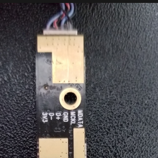
Some cameras show their pinout on the back silkscreen:
If you're not so lucky, you will have to find the proper pins one-by-one. Here's how:
First, find and solder the GND pin. The gold-plated rings around the mounting holes on the camera PCB are connected to GND - so take a multimeter. By the way, the connector's shield pins are often NOT connected to GND.
Then, look for VCC - find the nearest capacitor to the connector, then find the GND side of this capacitor - the other side is likely to be connected to VCC. There are also other capacitors on the camera board, that's why I'm saying to look at the closest ones. If you can't find the VCC pin, just find the D+/D- pins, the one pin that's not data or ground-connected is exceedingly likely to be VCC.
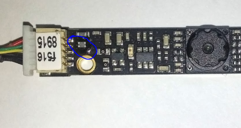
D+/D- wires are often twisted, not always, but when they are, it's a dead giveaway. D+/D- pins are usually connected to a small filter on the PCB:
Just use your multimeter to find which pins of the connector are connected to this filter, these will be your D+ and D- pins. Also, if you end up tearing off the D+/D- pads, this filter is where you'll be able to take the missing signals from (though you will need to use 0.1mm magnet wire and a fine-tip soldering iron, anything else will just cause more problems).
It's OK if you mix D+ and D- pins up, the camera just won't work - so if it doesn't work once you've soldered all the wires, try swapping the D+ and D- wires and then plugging the camera in again.
On high-end laptop cameras, there can be a fifth wire (one that's not involved with some kind of microphone) that is not connected to either VCC or GND. Try leaving it alone, but if the camera doesn't enumerate and doesn't cause USB errors either, try touching it to VCC or GND, it might be a "camera enable" pin.
Voltage
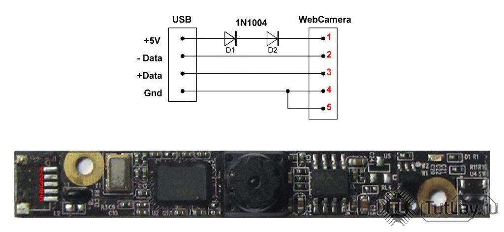
Laptop cameras work better with 3.3V, as they're designed for 3.3V operation inside the laptop. While it's tempting to feed it 5V from the USB connector (and many tutorials on the Internet suggest that), your camera is likely to either overheat or burn up. The best option is to add a small 5V-3.3V regulator (or use 3.3V directly if you're connecting your camera to a Pi), but if your budget is limited or you can't find a regulator, two diodes (regular, not Schottky ones) will also work:
![]()
If you use diodes, they have to have approximately 0.7V voltage drop. Diodes like 1N4007 (the 1N400* family) or 1N4148 will work! Schottky diodes (like 1N5819 and SS14) have a lower voltage drop and you risk burning a 3.3V camera if you use two of those, sadly.
Software (Linux)
Debugging
dmesg | tail for reading the last 10 kernel events, in case you've fucked up, it will mention something like usb 1-1: device descriptor read/64 . I recommend running dmesg -Hw & , that will make dmesg run in background and print USB events (among others) as they appear.
If your USB port stops working altogether after an experimentally plugged USB device and dmesg on your Raspberry Pi says this :
usb usb1-port1: attempt power cycle
Then disconnect the offending device and use this command:
echo 0 > /sys/devices/platform/soc/20980000.usb/buspower; sleep 1; echo 1 > /sys/devices/platform/soc/20980000.usb/buspower
It will reset your USB port. However, if you plug the device again and it will be faulty, your port might error out again. Also, this command might not work on full-sized Raspberry Pi that have 2 or more USB ports - this command crashed the Pi3 I tried it on. However, it's also possible the Pi3 USB port will not be susceptible to this problem.
Camera info
Isusb to list the USB devices connected, show the USB VID/PID and the USB device name (the name is not necessarily useful and is taken from a database that's stored inside your Linux distribution). There are all kinds of lsusb options to get more info, i.e. about specific devices - use man lsusb to learn about these.
v4l2-ctl --all can be used to show general-purpose information about a camera
v4l2-ctl --list-formats-ext can be used to show resolutions and formats supported by the camera (including the hardware-accelerated outputs)
UPD on pinout decyphering woes from @Joel :
>>> (Joel) a strange thing I noticed. on two of the HP cameras, the ground was not grounded on the shield or ground holes >>> just thought that was a bit strange and may want to add it in the post >>> also the red/black wires were reversed <<< (me) true. I see that sometimes with the shield, never with the holes. thank you! [...] <<< what was the method you used to determine the right polarity in the end? >>> actually I was wrong, one of the HP cameras was grounded on the holes. so I could use that to tell that the polarity was revered from that. I then had a newer HP camera with the same wire colours, but no wires where grounded on the holes, so took a chance with the reversed polarity and it worked -
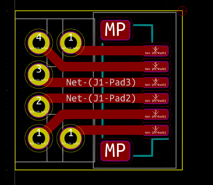
FPC adapter for reusing cameras
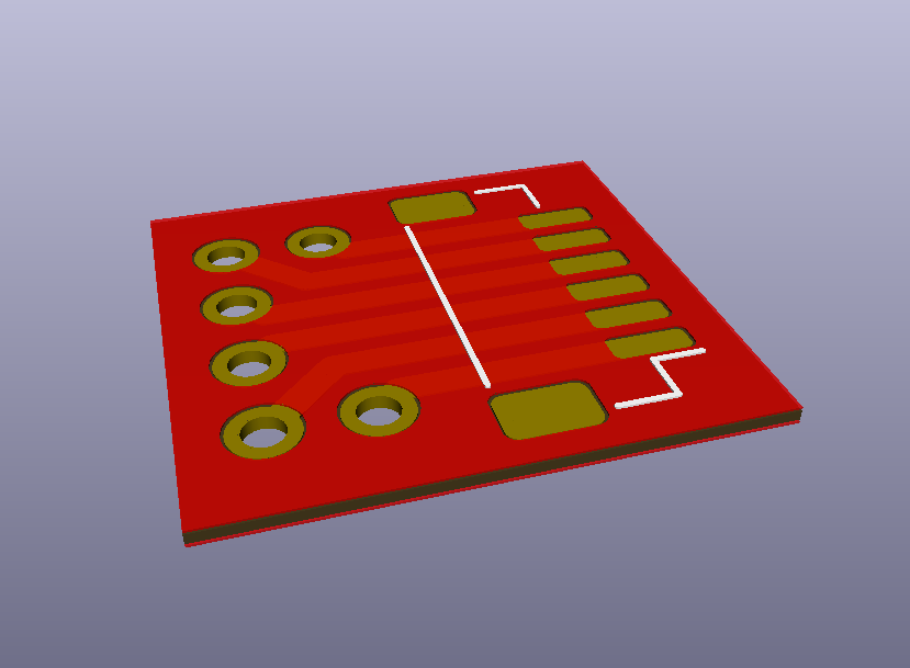
05/29/2019 at 13:37 • 0 commentsThis is an adapter that lets you connect USB wires to the camera easily, so that you don't need to solder thin wires to the connector's pads or reuse the original wiring. You can find the KiCad files in the "Files" section of this project.
![]()
This adapter is pinout-agnostic - no matter the pinout of your camera, which pins are ground and which are data pins, it will work. It also gives you a way to solder the FPC adapter to the shield pads on the PCB so that it's harder to accidentally tear the flex adapter off of the solder pads. Also, it accepts some variations in the connector pad pitch - I've printed it out and it works on the cameras I use, even if the connector pitch is a little bit smaller than 1mm.
Once the design is finalized and I have a chance to test it, I will make usage instructions and sell these on my Tindie store. In the meantime, you can use this OSHPark link to try it out yourself!
![]()
This adapter is designed for 6-pin cameras, so you can use it even on cameras which have microphone pins and try to reuse the microphone, too. If you don't need all the 6-pins, you don't have to solder all of them.
Laptop Webcam Reuse Made Simple
Showing you how to reuse laptop webcams in your project