Casual Cyborg
-
Moving right along, and getting through the first round of the Hackaday Prize 2018
09/06/2018 at 16:38 • 0 commentsWhoah, I wasn't expecting that. Apparently, the BodiHub made it through the round of the Human Computer Interface Competition!
Twenty Projects That Just Won the Human Computer Interface Challeng
I was surprised, as I've been working on this thing for two years now, and been continuing on it through out this year and last year. I also noticed some peeps were miffed that I didn't have the required four build logs, and that there were three listed. Here are the previous nine build logs if you want.A Wearable, IoT+ANN Dev Board for Body Sensing
I'm just too lazy to go and cut and paste all of the months and years previous work, especially all the work that occurred outside of competition in between 2017 and 2018, for the new entry, partly because I think that's wrong to do, but I also don't think I should discount my work that was happening outside of competitions.
I actually had a discussion with one of the Hackaday people, who was trying to convince me to enter my work into the competition, and I almost didn't enter, because he stated that I had to start a whole new project page for it - it has to do with getting enough likes to get some seed money. I wasn't keen on that idea, and I felt like entering would've been a waste of my time, as I wasn't in the mood to just start a whole new project page just to compete. When you've spent almost a year and a half, on a project page building a following, you can see why it doesn't make sense to make a whole new project page just for the competition.The reason is my previous project page is also a market test page, to see how many people would be interested in the project. If there's enough people interested in it, it justifies me to go ahead and do a production run of these development modules. If not, I can't justify spending the money to do it. Hardware is hard for a reason, and it costs money to bring a product out. It's not like software.
Now, why am I taking that approach?
I learned some really really harsh lessons from this project, from my defunct startup company,
SynthaSense Suit: Control Stuff With Your Muscles
When you blow your life savings and three to four years of your life on something the market isn't really interested in, that's a harsh ass lesson to stomach. I got spanked pretty hard. And I always, ALWAYS learn my lessons.
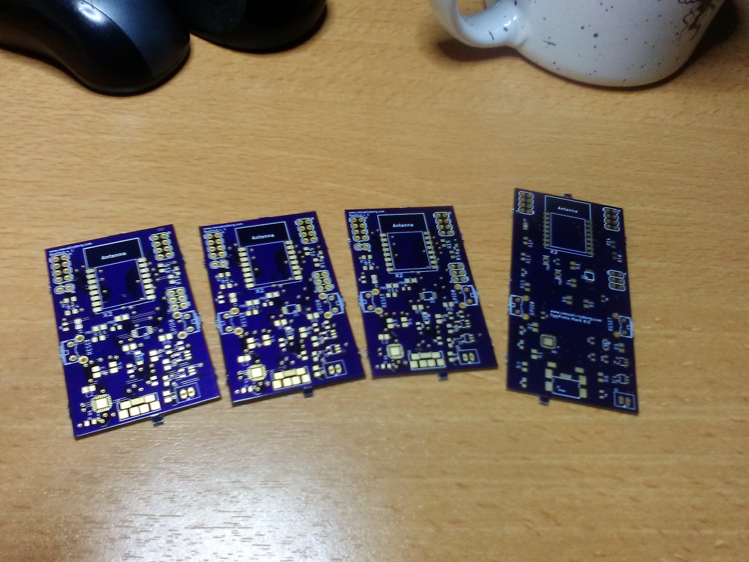
Anyway, it'll be up to the judges to decide if the large amount of work I've done before this competition previously should or shouldn't be allowed to qualify as part of the build. Which I personally think is a disservice, because this kind of project takes way way longer than just the time during the competition to do. Many of us do work full time jobs.Moving on, I've been working steadily on the board, but have also been working to get a startup company on a firm footing, so things have slowed down a bit. This capital infusion should help me get the 3rd iteration of the boards done though. Pictured below, is iteration 2, thanks to Oshpark. You can see it next to the first iteration 1, which is to the right.
![]()
Stay tuned! -
Testing the BodiHub's Interconnectibility
04/18/2018 at 21:12 • 0 comments![]()
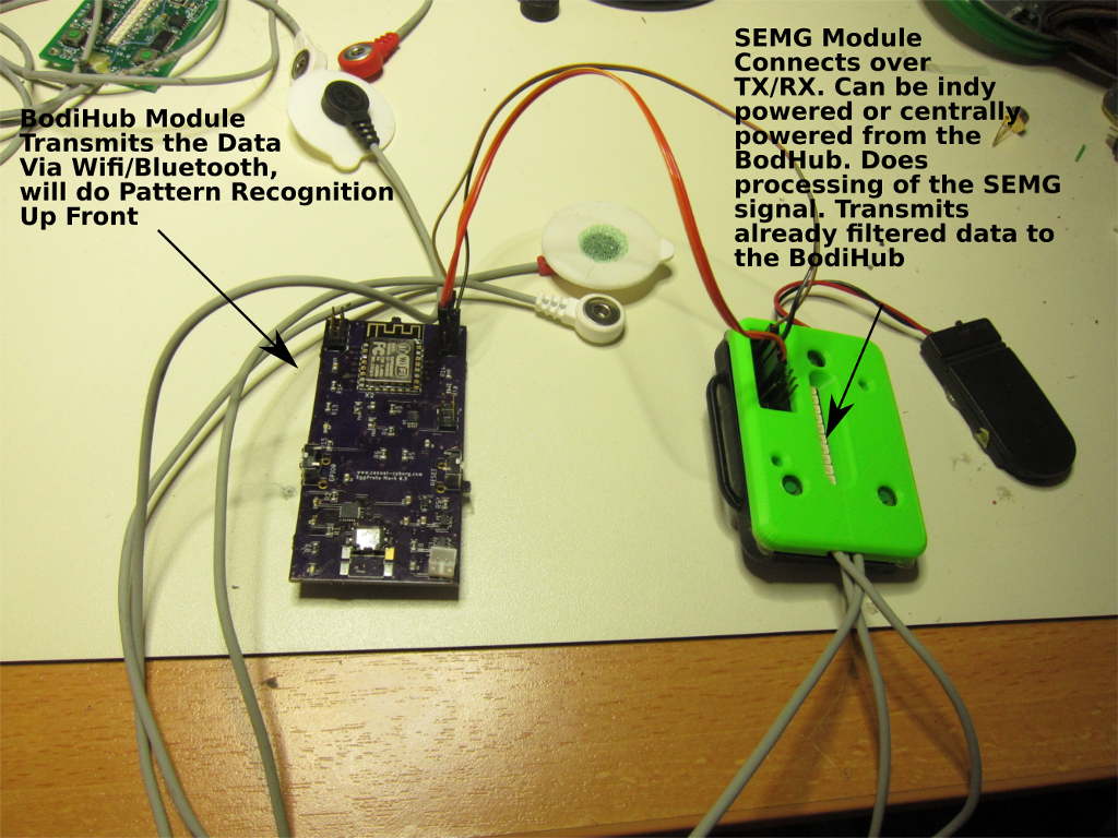
Cyborg's gonna cyborg. It was nice out today, so I went to do a quick concept photo shoot with the BodiHub system. You can see how I've connected a body sensing module, my SEMG unit, with the BodiHub.
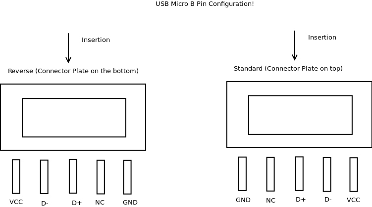
I'm in the middle of cleaning up version 3 of the PCB board. With some advice from the HacDC folks, and some finagling, I've got the USB micro B connector replaced. Oh, and if anyone out there wants a reference on those freaking things, here. I can't believe how much time I lost just hacking around it and making do to get it to work.![]() We're going to send out the revised board tomorrow to fab with @oshpark . I also learned of another technique to make the boards even smaller and compact, using stencils, so I'll be sending out for stencils with oshstencils. In the mean time, today I tested out the interconnecting feature of the board, using one of my old SEMG modules from my defunct startup company. You can read more about those modules here at Control Stuff With Your Muscles.
We're going to send out the revised board tomorrow to fab with @oshpark . I also learned of another technique to make the boards even smaller and compact, using stencils, so I'll be sending out for stencils with oshstencils. In the mean time, today I tested out the interconnecting feature of the board, using one of my old SEMG modules from my defunct startup company. You can read more about those modules here at Control Stuff With Your Muscles.
The idea with this is to test out the inter-connectors, and the functionality. Here's a preliminary setup of the concept.![]()
The SEMG isn't the only module that can hookup cleanly to the BodiHub. IMU sensors, accelerometers, gyroscopes can also hook up in clean configurations to it. And then there's the analog ports! I have flex sensors that I want to use to balance against the IMU sensors for a much better body kinetic measurement system. They're all analog - hence the reason I wanted dedicated ADC units, not the crappy one that comes with the ESP8266 or ESP32 - so I'll have a preliminary concept picture out on how those will be set up pretty soon.
In the meantime, I've replaced the reversed USB Micro B port <Damn You Hirose! Damn You!>, and added a whole bunch of improvements which should prove valuable to hackers, like extra pins for more ports in case something gets hung up, etc. I was going to open up the REGIN of the CP2104 to make for a dual redundant power supply, but given that it's not recommended just in case one voltage varies just enough with another, I went against it. I do have a nice 600mA power supply on there, and I'm looking to juice that higher to 800 or 900mA, which should take care of most power hungry needs AND the antenna transmission system.
Stay tuned, and keep hacking!![]()
-
Assembling the Board Pt 3: Finding ESP8266 tips you have to hunt really hard for.
04/05/2018 at 17:55 • 0 commentsIt's alive! It took me a while to find out that any ESP8266 you work with, has to have at least 300mA in juice. And that 3.3V power supply coming off of your USB to UART that you're using to communicate and power your ESP8266? Ain't gonna cut it. Most USB to UARTS have at most 18.5 mA. It wasn't until I soldered on the 3.3V regulator which has a minimum of 600mA that the board started working properly.
Before that, I was getting all kinds of weird reboot errors, strange memory address registers on the serial terminal, and strange blinking lights off the board itself. It was weird too. I could upload and flash the memory, and I'd get hardware puke in return. After many, many hours looking it up in forums, blog sites, and... goddamn, I think I'm also going to write an FAQ on the ESP8266 to save other people this kind of headache. Anyway, after all that, it was this one forum post in sticksville internet, that some dude said he never runs the ESP8266 without some kind of external power source that IS NOT from the USB to UART.
That's when I had that "Ah, F--K ME!" moment.
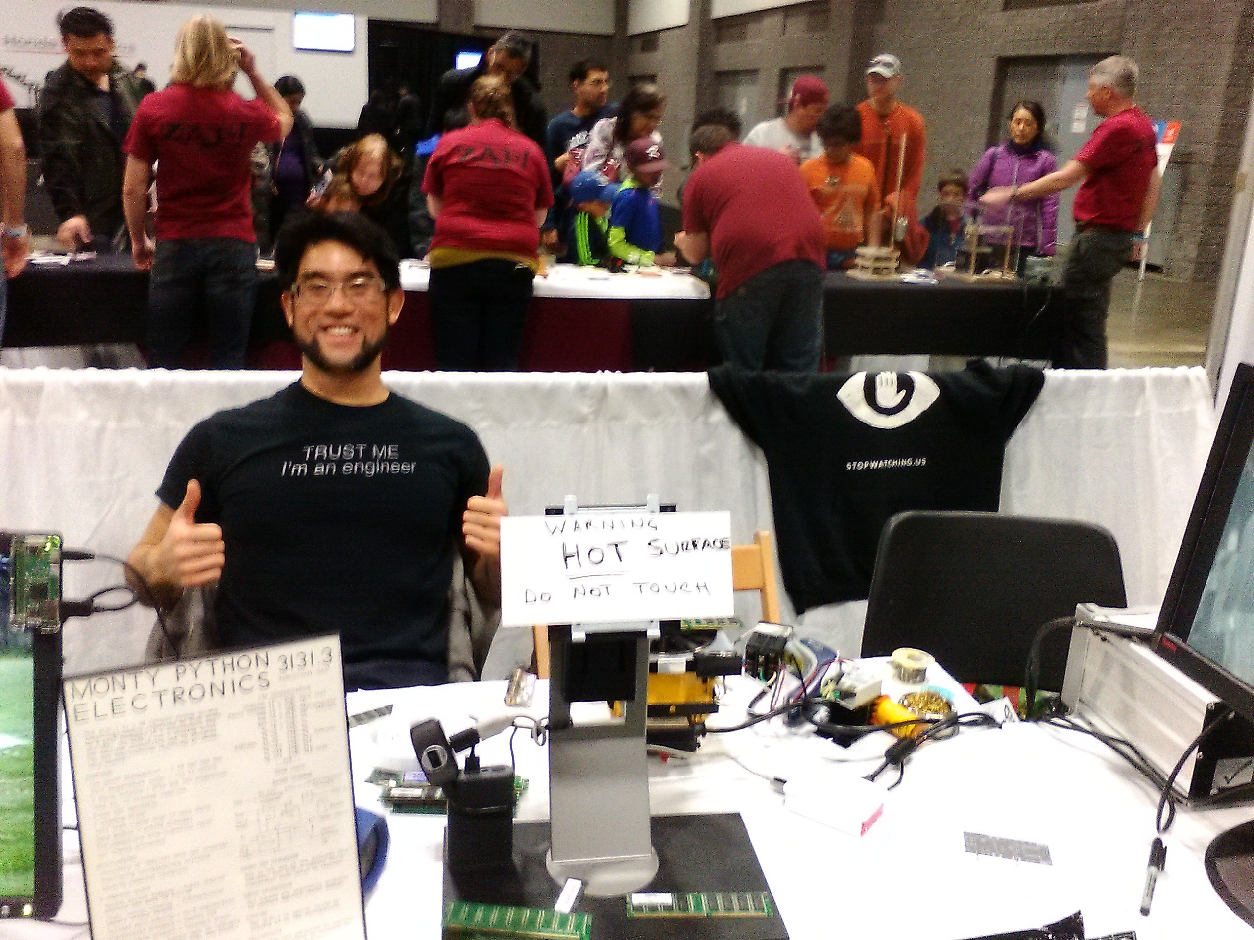
Now? It runs smooth as butter! Check it out!This is the board with the typical blinky light "hello world!" program.
And this is the board talking to the web via WiFi! Up next! More hardware revisions, cost cutting, do you really need that on the board, and some concept photography! Because I always need an excuse to put on a lycra jumpsuit. OK, OK, it's to demo how we're going to mount the bodihub onto the body, where the sensor channels are, and what this thing can do. Plus, hey, it's always fun to feel like you're a high tech superhero from a comic book...
![]()
HADOUKEN! -
Assembling the Board Part 2: If at First You Don't Succeed...
03/30/2018 at 17:43 • 0 commentsFor the previous blog entry, read Assembling the Board Part 1: Fried Board Recipes.
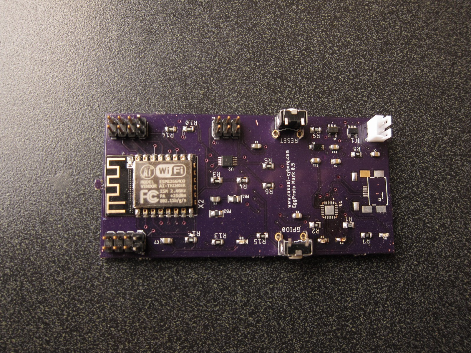
So I managed to finish assembling the rest of the subsystems of the board.
![]()
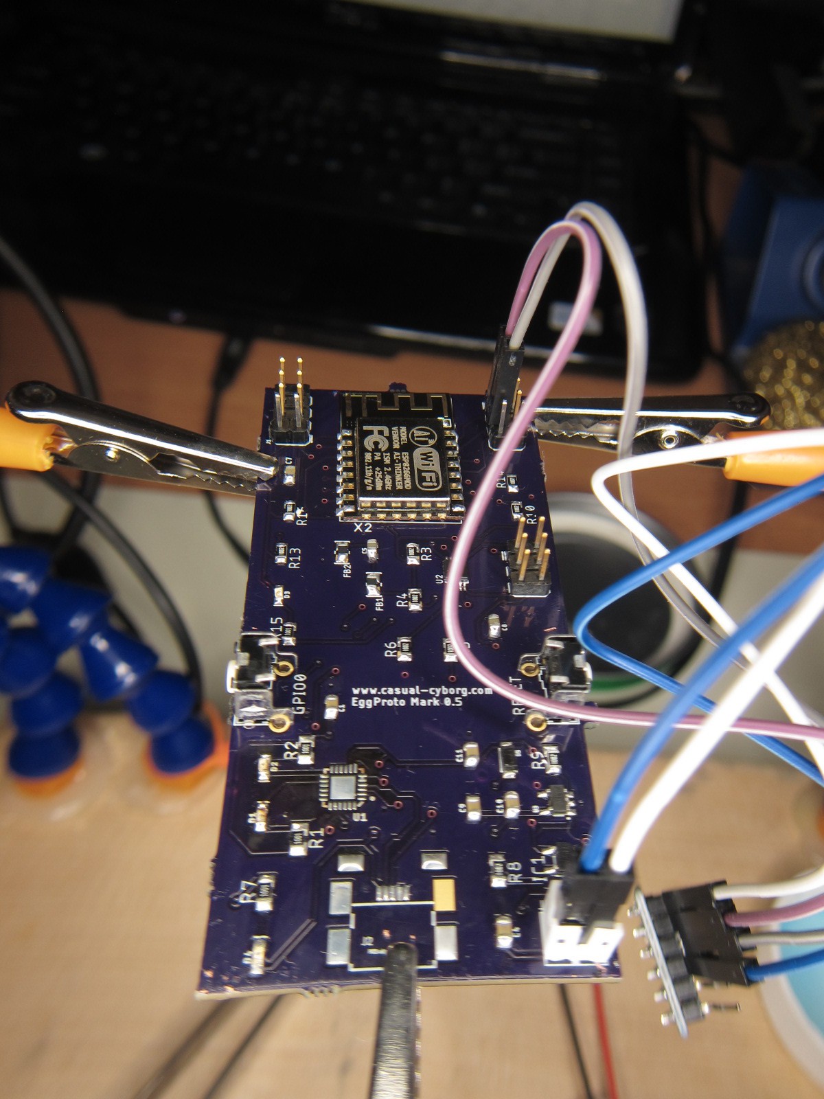
After, I think 3 more attempts to solder on the QFN package, and finding that the voltages of the CP2104 weren't, well, doing what they're supposed to be doing, eg. I have a VBUS of 4.75 V, and there "should" be a VOUT of 3.45V, only to see 1.6 Volts coming out, I decided, OK, you know what? Let's just get the other subsystems that I know should be working, working. which means the ESP8266 and its supporting electronics, the redundant power supply and battery charging system, and the ADC system. None of those have strange soldering issues. I'm not sure if while doing the hot air method if I basically shorted the CP2104 and did something odd to it, or what.
So, to see if I could get some answers, I headed over yesterday to HacDC, where I met one Julia Longtin, who placed in the 2014 hackaday quarterfinals with her Microwave Aluminum Printing Technology.
Julia pointed out that I was hitting a problem with temperature differentials in the QFN package, the solder, and the board itself. The board needed to be at a higher temperature for the solder and the chip to adhere solidly. Which meant heating the board, either with a soldering hot plate, an electric skillet, or with a freaking flood light?!!
Given how new I am to hand done SMD/SMT soldering, Julia gave me a crash course in using a flood light that we salvaged from HacDC's extensive, um, "storage" facility, aka place where a lot of stuff ends up. Anyone need an analog oscilloscope? They've got tons to give! Shoot, I have two to give...
So, the next thing I need to do is to get a hot plate, and some ramen. Because SMD soldering gets me pretty hungry. Till then, I have to make do with the board like this:
![]()
The other problem I ran into is I specced out the incorrect USB micro B connector! It's times like these where I wish I was in Shenzhen. Instead of hunting through an online catalog at Mouser.com, reading confusing datasheets where the mechanical designs aren't always up front, I'd much rather be able to go out the door, go to a shop, and check out what they've got, touch em, feel em, take a look and get a good idea of what I want. This whole catalog and pray method isn't the best way to prototype.
Up next, more adventures in SMD/SMT soldering, and creating some of the first use cases! Stay tuned!
BodiHub
A Wearable, "Smart", Internet of Things Development Board That Learns

 We're going to send out the revised board tomorrow to fab with