 makeTVee
Check the videos on Youtube
0%
0%
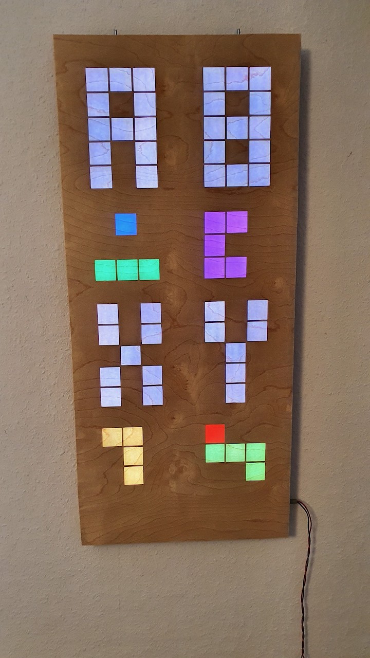
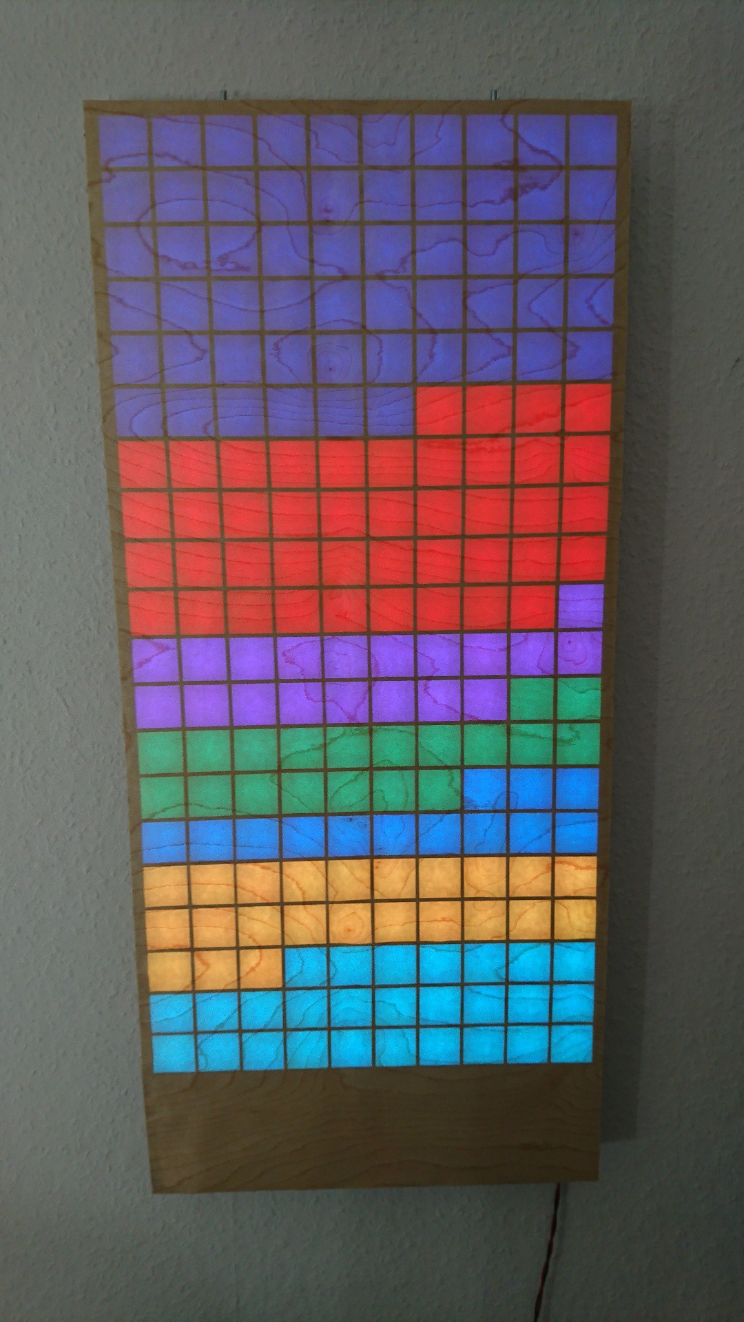
Raspberry Pi Retro Gaming LED Display
20x10 WS2812 LEDs driven by Raspberry Pi/Arduino to play games like Tetris in the living room
Become a Hackaday.io member
Already have an account? Log in.
Just one more thing
To make the experience fit your profile, pick a username and tell us what interests you.
Pick an awesome username
hackaday.io/
Your profile's URL: hackaday.io/username. Max 25 alphanumeric characters.
Pick a few interests
Projects that share your interests
People that share your interests


I've been looking for details for building something like this. Looking forward to seeing more about it and diving into the details.