Educational TTL
This is an attempt to create some hardware that may help to learn digital electronics and will be cheap enough
This is an attempt to create some hardware that may help to learn digital electronics and will be cheap enough
To make the experience fit your profile, pick a username and tell us what interests you.
We found and based on your interests.
protolgx3.zipGerbers for "no-breadboard" logicZip Archive - 22.29 kB - 06/01/2016 at 06:08 |
|
|
bblock4.pcbgEDA PCB version of NAND for breadboardpcb - 30.93 kB - 06/01/2016 at 06:08 |
|
I built and tested both versions of educational TTL:
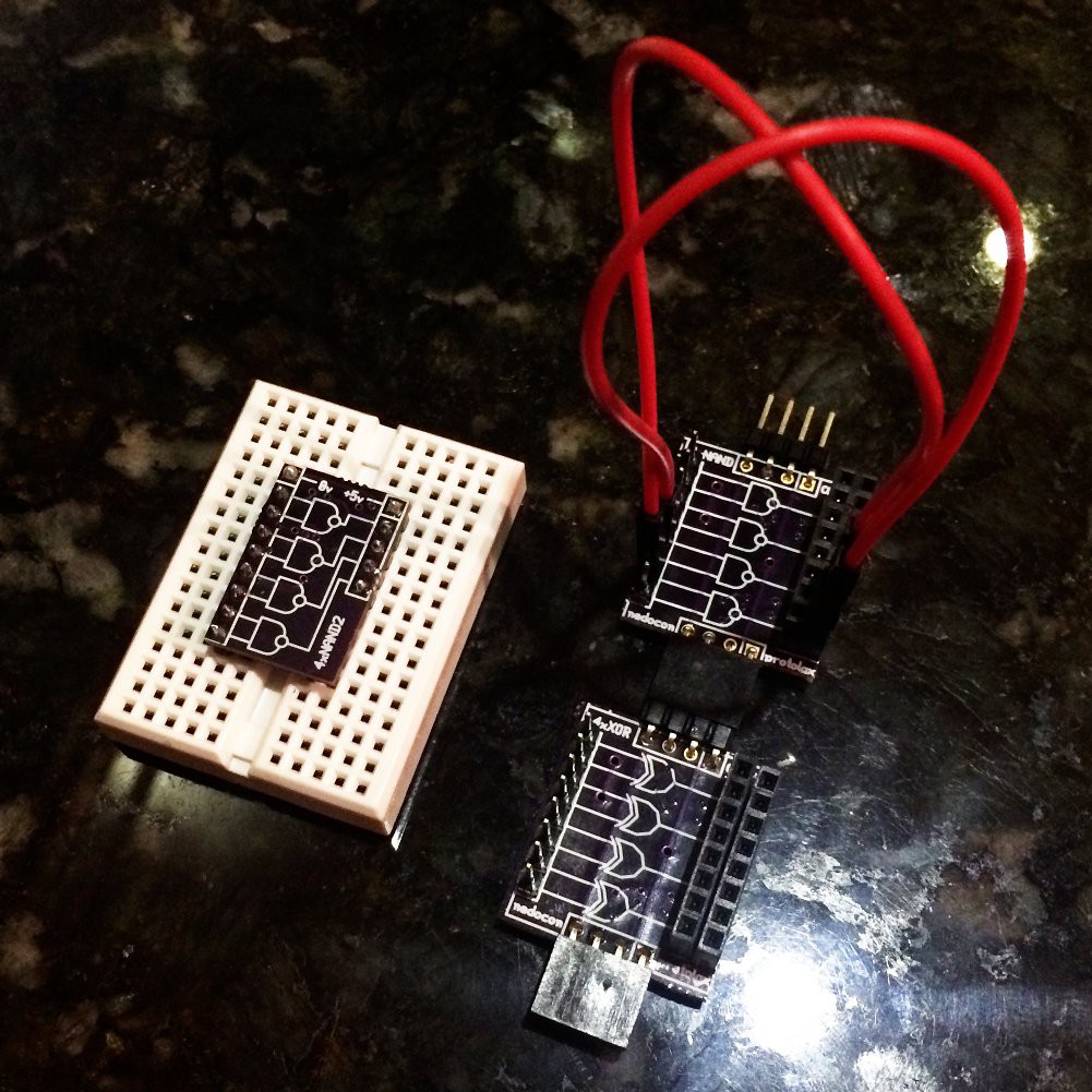
Unfortunately "no-breadboard" one has some outputs routed in wrong order :(
How breadboard one works is clear (I hope), but "no-breadboard" one needs some clarifications I believe - so as you can see inputs are male pin-header and outputs are female header receptacles - you should use special jumper wires where one end is female and another end - male. This way you never connect multiple outputs to the same input - it's simply not possible. So "no-breadboard" version is kind of breadboard by itself. Also on the top of every board you can see 4-pin header that is connected to bottom receptacle of other board - they bring ground (2 middle wires) and power (right wire) to every board. I imagine some kind of backplane on the top (top-plane?) where many columns of boards attached for power and ground.
I need some input from Hackaday community - which approach is better and should be elaborated deeper? Breadboard one or "No-breadboard" one?
P.S. I attached PCB source code for "breadboard" version and Gerbers for "no-breadboard" - as I said before it has ERRORS, SO USE IT ON YOUR OWN RISK!!! Link to OSHPark project for 1st breadboard version: https://oshpark.com/shared_projects/SWuqir41
Boards for "no-breadboard" version of educational TTL arrived not so long ago:
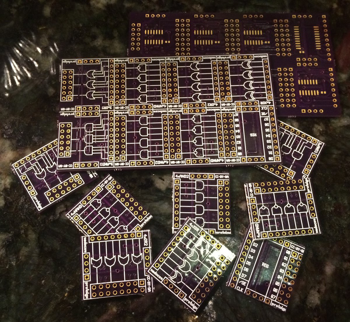
Different approach to avoid breadboard completely - here I/O-signals will be connected by wires and power will go from up to bottom (boards will be connected to each other by 4-pin headers):
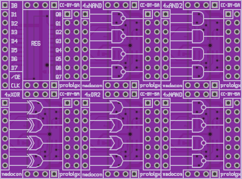
This is 1st attempt - board that I created in September 2013, but didn't share it yet - now I do this:
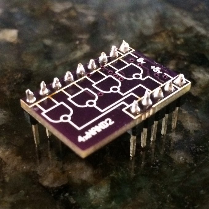
On the front it has an image showing what is that:
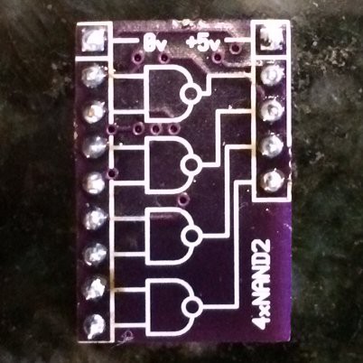
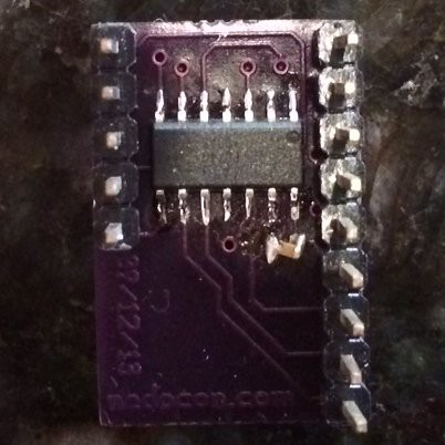
and on the back it's 7400 chip in SOIC package with SMD 0.1uF capacitor on power lines:
Create an account to leave a comment. Already have an account? Log In.
I wish I had something like this when I first started digital electronics. Instead I had a TTL book from the 80s or 90s and the pinouts it had in the back.
Become a member to follow this project and never miss any updates
By using our website and services, you expressly agree to the placement of our performance, functionality, and advertising cookies. Learn More
I love it!