Close
0%
0%

SUPEROLED8

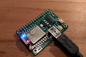
Development board for ATmega32U4 complete with 128x64 OLED and 5 way navigation button.

Similar projects worth following
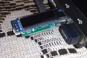
You know all of those used ATmega32U4s you have laying around the workbench? That’s how this idea started - I designed a breakout board to test them. The designed for the SUPEROLED8 is based on my tool, the OLED Backpack for the USB Tester (a USB power measurement device) since it’s a proven design. Completely open source, this little board gives a hardware starting point with plenty of options. From a simple breakout board, it has turned into development board that I hope will inspire other projects.

As I work on this, I hope to improve the demo firmware, provide additional examples, finish designing the 3D printed case, and look into designing add-on boards.

An OLED development board with 5-way navigation button in a small form factor for those that don't want to mess with designing their own hardware. Easy to use with the Arduino IDE or you can use Atmel Studio or your favorite environment that supports the Arduino Leonardo.

Hardware:

The design is based on my existing tool, the OLED Backpack for the USB Tester (a USB power measurement device). Most of the SUPEROLED8 is the same, minus the current sensing hardware and connections that attach to the USB Tester. In the second iteration I swapped the single button for a 5-way navigation button with a 2k resistor network to share a single analog pin. This saves four GPIOs for other uses. The unused GPIOs are broken out at the bottom and just below the micro USB connector. The UART is above the 5-way and I2C at the top left of the OLED display. Add-on hardware can be connected to the bottom to add more features, like sensors or various power options, for example. The PCB form factor is based on the Dangerous Prototypes Sick of Beige standard PCB sizes.

Firmware:

The demo code is a small 5x5 pixel filled square that you can move around with the joystick. The 5-way button is sampled via a single ADC and depending on the value, it is mapped to a button press. I’ve yet to work intensively on the firmware, but that is one of my current goals.

SUPEROLED8_Board.png

Portable Network Graphics (PNG) - 229.80 kB - 05/30/2016 at 02:18

Preview

SUPEROLED8_Schematic.png

Portable Network Graphics (PNG) - 56.04 kB - 05/30/2016 at 02:18

Preview

  • 1 × OSHPark PCB
  • 1 × ATmega32U4 Microprocessors, Microcontrollers, DSPs / ARM, RISC-Based MicrocontrollersMic
  • 1 × 16Mhz Resonator
  • 1 × 128x64 OLED OLED Display
  • 1 × 5-Way Navigation Button

View all 14 components

  • Center Button Test

    MobileWill05/30/2016 at 02:30 0 comments

    One thing that was missing is the use of the center button. The point of the demo is just to make sure all the hardware works. I added a simple X/Y reset when pressed. So if you loose the box outside the bounds of the display it will reset to the center. It’s a bit hard to hit the center button until I reprint the case for better movement of the joystick. The center button also turns the LED on for a bit, but it is hard to see until I print the joystick cap in a clear filament.

    void bCClick(){
      boxX = 64-boxXSize;
      boxY = 32-boxYSize;
      digitalWrite(LEDPIN, HIGH);
      delay(200);
      digitalWrite(LEDPIN, LOW);
    }


  • Larger Joystick Hole

    MobileWill05/30/2016 at 01:53 0 comments

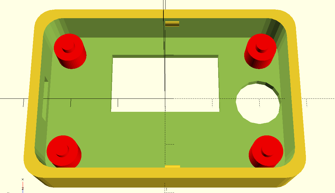
    After working on the box demo, I realized the hole for the joystick needs to be a bit larger. In some directions it touches the hole’s edges. Here is a picture of the larger hole. I haven’t had a chance to print it yet but it should be the right size now.


  • Faster Demo Box

    MobileWill05/30/2016 at 01:52 0 comments

    Along with the recent Bay Area Maker Faire and some other projects, I haven’t had much time to really work on the SUPEROLED8. The one change I did do was increase the repeat rate so you can hold the joystick and the demo box will move across the screen much faster. Here is a quick GIF of it in action.

    I switched from using the AnalogButton library to doing my own simple analogRead while updating the position. It’s much better! The use of the library kept things nice and it added other options like hold. It would be up to the user which to use, depending on their project.

  • Analog Button Values

    MobileWill04/20/2016 at 04:37 0 comments

    Here are the values used to read which pin is depressed via a single analog input.

    • None - 1023
    • Center - 453
    • Up - 382
    • Down - 0
    • Right - 169
    • Left - 290

View all 4 project logs

  • 1
    Step 1

    Hardware:

    After the board is populated all that is needed is to solder the display. I usually test the board and display before soldering since it is difficult to remove the display. If you hold the display at an angle, once the firmware is loaded, you can see if it works.

  • 2
    Step 2

    Firmware:

    This design is based on the Arduino Leonardo and therefore uses the same bootloader. Using an AVR Programmer the bootloader can be flashed by the Arduino IDE.

    Once the bootloader is loaded the demo sketch can be downloaded from the Github link and flashed the same way you would any Arduino.

View all instructions

Enjoy this project?

Share

Discussions

Boian Mitov wrote 06/01/2016 at 18:12 point

Cool! I just finished adding the first version of OLED support in Visuino :-) .

If you send me one, I can see to add support for the board in Visuino ;-) .

  Are you sure? yes | no

Black Brix wrote 05/10/2016 at 07:20 point

Hi,
very interesting project.
where to buy this OLED Display ?

  Are you sure? yes | no

MobileWill wrote 05/10/2016 at 19:44 point

Thank you. You can get them from our shop. friedcircuits.us. There is also a bread board adapter option since the display is 2mm pitch.

  Are you sure? yes | no

Similar Projects

Does this project spark your interest?

Become a member to follow this project and never miss any updates