 Walt Perko
-
1Initial Powering of the RoboGuts™ circuit board ...
Hi,
I've created several images showing various ways to power the RoboGuts™ circuit boards.
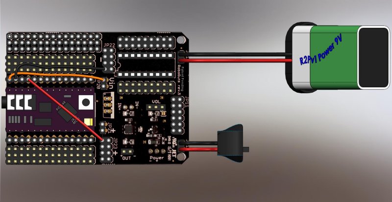
Standard 9V radio battery power:
![]()
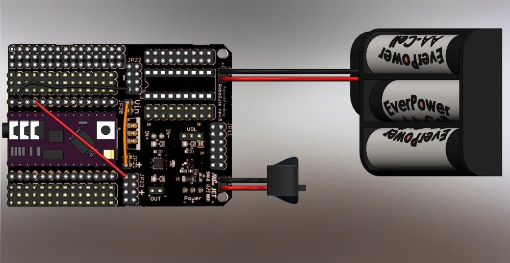
4.5V Power from 3 AA cells
![]()
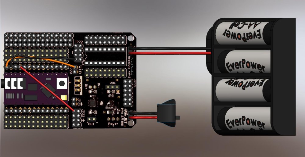
a 6V source such as 4-AA cells;
![]()
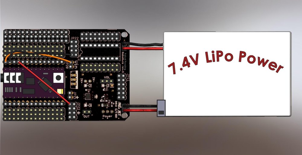
Got a LiPo battery pack? 2P = 7.4V or 3P = 11.1V works well with the RoboGuts™ circuit boards;
![]()
The board will work from 3V to 12V depending upon the MCU chip or module selected, my demonstrations are with the PICAXE 28X2 module which has its own voltage regulator onboard, but cannot supply too much power for big projects, but is great for building the miniFloppyBots or a BillyBot ...
Find all sorts of info about powering the RoboGuts™ circuit boards in the "Teacher Notes" on the lesson page: http://www.r2pv1.com/PICAXE28X2m/
-
2How to use the lesson pages ...
Hi,
The lesson pages (http://www.r2pv1.com/PICAXE28X2m/) are setup for anybody to use ... all you have to do is look at a lesson image, put jumper wires on your RoboGuts™ circuit board exactly as you see them in the lesson image. Once you are sure your board is properly powered and the lesson jumpers are correct then click on the lesson image to reveal the lesson BASIC language programming code. Copy the code, then paste it into the FREE programming editor (http://www.picaxe.com/Software/PICAXE/PICAXE-Editor-6/) and program your MCU to perform the lesson.
Next, you can experiment with the lesson by changing which PIN is connected to the component and making the appropriate change in the BASIC Language program (e.g., move the jumper wire from PIN B.1 to maybe PIN B.7 change the program code from "symbol LED = B.1" to "symbol LED = B.7" and see the lesson function again.)
RoboGuts™ S.T.E.A.M. Education Program
RoboGuts™ S.T.E.A.M. education program where teachers only help students find answers and solve problems to innovate and create.
Discussions
Become a Hackaday.io Member
Create an account to leave a comment. Already have an account? Log In.