 Andrew Starr
I have a new sense amplifier design:
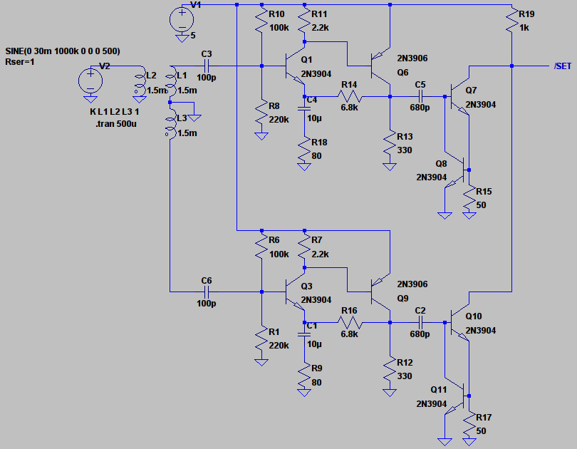
It consists of 3 sections: a pulse transformer front end, a complementary pair amplifier, and a constant current sink output. The amplifier section has some negative feedback that should help stabilise the gain vs temperature, and the input and output of this section is AC-coupled, which should further help prevent the issues experienced with the previous (crappy) design.
In common with the last design, this amp is dual-channel to catch both positive- and negative-going pulses, and the current sinks are wire-ORed together.
Gain is adjustable via R18/R9. I will use a ganged trimpot, if such a thing exists.
Discussions
Become a Hackaday.io Member
Create an account to leave a comment. Already have an account? Log In.
Save 2 transistors by adding 2 diodes? Why bother :) And a differential pair is problematic without a reference or negative rail, and likely to add even more components...
Are you sure? yes | no
There are some good reasons to bother :-) power consumption is halved, heat generation and sensitivity drop, costs drop too, smaller board...
You could also get a high-ratio transformer to easily amplify the signal, then use a low drop full-bridge to rectify the pulse.
Are you sure? yes | no
Eliminating 2 transistors i.e. 1 current sink is not going to affect power consumption, cost, board size or heat generation in any significant way.
The high-turns ratio pulse transformers I have looked at are physically too high to fit in the gaps between the modules. And even using a rectifier, I'd still need to follow it with a stable adjustable-gain amplifier (remember I need a current sink output).
Are you sure? yes | no
Daaaaamn... I thought that my DRAM was hard....
Are you sure? yes | no
If outputs are wire-ored, why not diode-or them and save 2 transistors, thanks to a common current source output ?
A differential pair (ECL-like) might also be useful...
Are you sure? yes | no
Your DRAM _is_ hard :) My eyes watered when I saw all those caps and diodes on that proto board...you know, a double-sided PCB isn't that expensive and would possibly save you a lot of grief!
Are you sure? yes | no
Are you kidding ?
of course, double sided PCB will be used :-)
For the prototype however I couldn't wait for the design to be sent back from Asia, and I need to fix things easily. The final 8×16 modules will be different of course.
knitting core memory OTOH is totally savage. I'm a ridiculous clown, but you're a Spartan soldier !
Are you sure? yes | no
I hope not, things didn't end well for them :)
Are you sure? yes | no