ThunderSqueak
-
A look at some of the tools used while I wait for parts: Programmer
04/26/2016 at 00:32 • 0 commentsI decided to take an image of some of the tools that are going to be used for this project while I wait for the rest of the parts to arrive in the mail... and explain a bit about them.
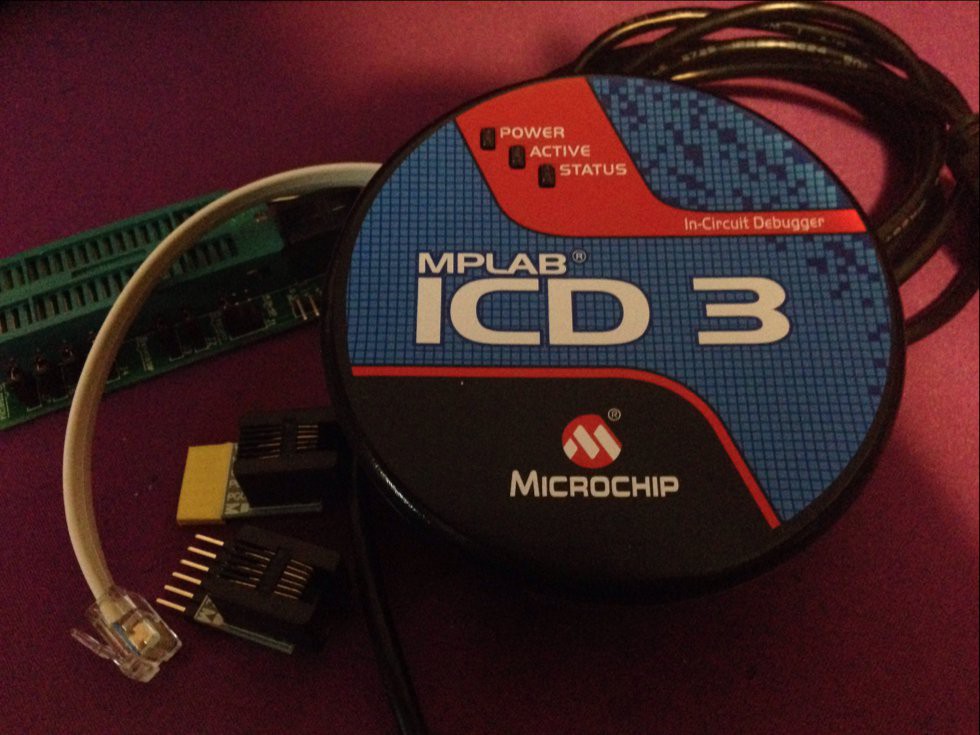
This is the ICD 3 made by Microchip. I had to add a couple adaptors to make it usable but it has some very nice advantages over the pickit programmers. The first one is that it is a lot faster, the wait time is almost half when programming a device with new code. Something that I seriously appreciate.
The other primary advantage this device has is that you can set complex breakpoints when you are ready to debug your project.
In other news, I should hopefully have the parts I ordered for this project in the next couple days. I am seriously looking forward to their arrival. :)
![]()
-
Basic Schematic for first version
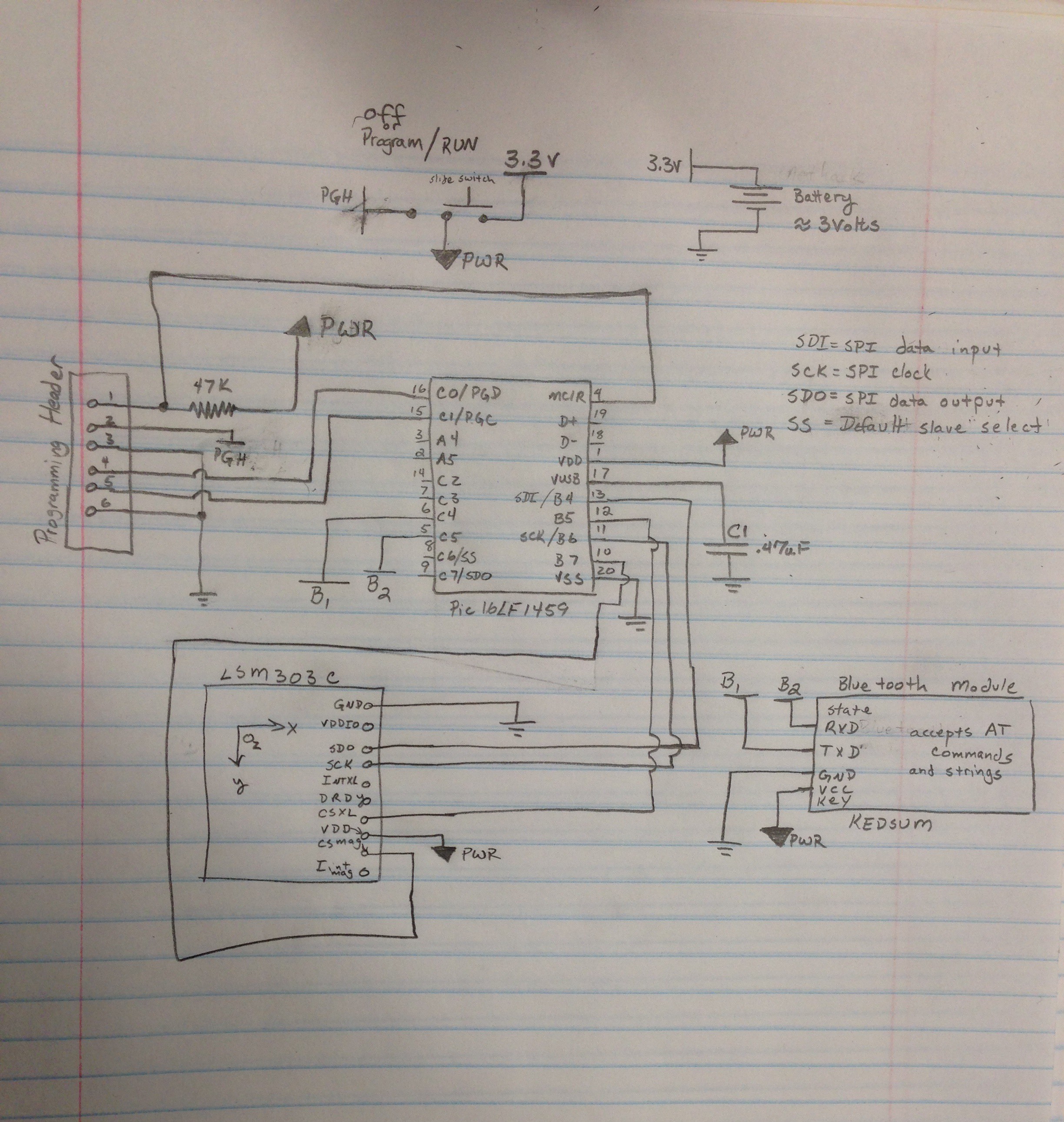
04/22/2016 at 19:53 • 0 commentsUsing my favorite CAD software, I drew up the initial schematic. As you can see, the circuit itself is pretty small, but this is good. Fewer components means smaller package and lower battery usage. There are also still pins left over on the chosen micro controller and if I want to add a USB functionality later it can be done with minimal changes. In a future revision I may also add a recharge circuit for a standard LiPo battery.
One of the ideas that I had was to build the circuit itself using the smallest components possible and building them into the actual battery enclosure.
![]()
![]()
-
Ordered Bluetooth components
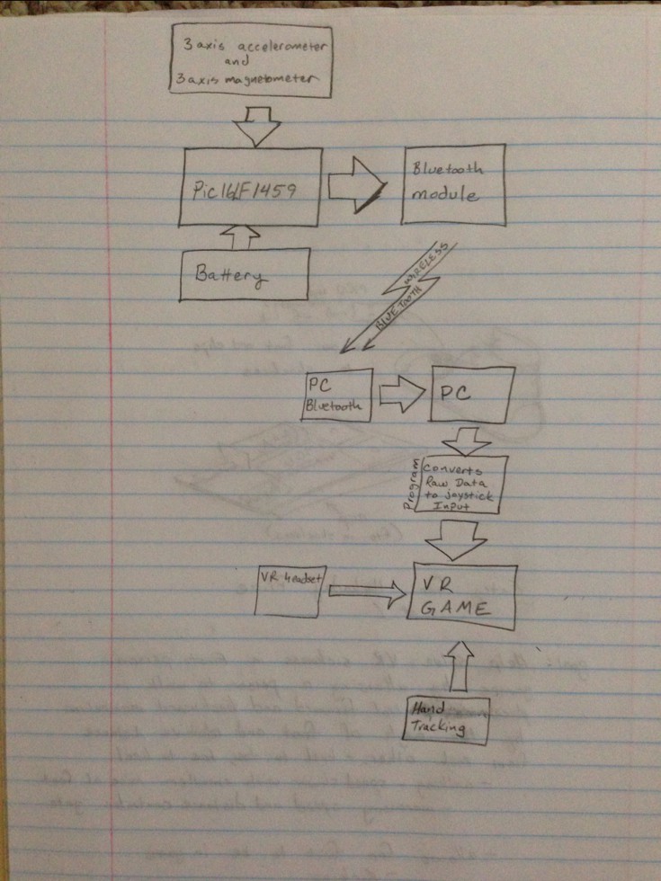
04/21/2016 at 03:00 • 0 commentsI ordered the components to make each foot wireless, so far the block diagram will look like this ..
![]()
-
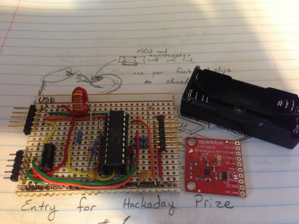
Scrounging for parts
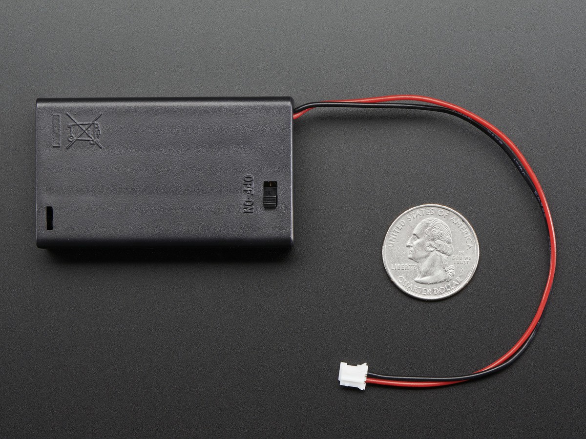
04/21/2016 at 01:43 • 0 commentsToday, I decided to scrounge around my parts bin for components to get the ball rolling. I found an old board I made featuring the pic16lf1459 MCU by picmicro, a battery holder, and after a quick trip to the local electronics shop, a couple sparkfun LSM303C. The final components and layout will be on a dedicated board eventually, however for now, this will let me begin development of the underlying code.
![]()
I still need to track down a bluetooth module to do the interface, and will be picking up a couple of those soon.
The LSM303C was a great find as it also has a 3-axis accelerometer and a 3-axis magnetometer in the same small package. The plan is to have this interfaced to the SPI bus and then using the USB features that the pic16lf1459 sports, send the data to a standard terminal on the PC.
Link for the LSM303C sparkfun breakout board: https://www.sparkfun.com/products/13303
Link for the pic16lf1459 MCU: http://www.microchip.com/wwwproducts/en/PIC16F1459
The schematic for the above is very simple with some basic supporting circuitry for the USB functionality. Programming for this is to be done with an ICD3, however you could also use a pickit 3 programmer with no problem. Code is to be written using the XC8 compiler suite.
You can find the IDE and XC8 compilers on microchips website here: http://www.microchip.com/mplab/mplab-x-ide
and
http://www.microchip.com/mplab/compilers
Project Hike - Walking in Virtual Reality
I love Virtual Reality but hate VR sickness, I decided to take a look at some options.... and a possible cure