-
New 2-transistor 4-state circuit
11/21/2018 at 15:13 • 0 commentsHi hackers ! In the spirit of this One transistor flipflop, I now have a 4-state circuit with only 2 transistors and LED's to show the state. No clock signal needed this time ! You find it here:
https://hackaday.io/project/162405-2-transistor-4-state-flipflop
-
4-bit TTL ALU
08/15/2018 at 20:46 • 0 commentsIf you are interested in flipflops, building CPU's might also be of interest to you.... I started a new project, a 4 bit TTL ALU with only 7 TTL IC's. It fits on a 1 x 1 inch PCB.....
And the next project is a TTL CPU on one square inch !
-
12 - transistor ALU
08/05/2018 at 07:49 • 0 commentsFor all who are interested in transistor logic..... Yesterday I designed a full-function ALU, see ALU in DCTL technology. It has only 12 transistors, two diodes and a few resistors !
-
On Hackaday.com !
04/19/2018 at 07:41 • 0 commentsI am very pleased to see that Brian Benchoff presents this project on hackaday.com today, https://hackaday.com/2018/04/18/the-one-transistor-flip-flop/ !
Thanks, Brian !
-
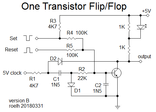
Improved version
03/31/2018 at 15:02 • 3 commentsOne of the drawbacks of the original design is, that it outputs a clock signal in one of the states.
I now have a different design that has a continuous high or low at the output. This will improve the useability of the circuit. Here it is:
![]()
I also added set/reset inputs. It is tested with a 500KHz clock.
After a RESET pulse, the transistor will be conducting, output will be LOW (and the LED is ON). The low transistor output also pulls the right side of R1 to a low level (through D2), this kills the clock signal.
During a SET pulse, the transistor will have no signal at the base, so it will stop conducting. The output will become HIGH (and the LED wil be OFF). The right side of R1 is no longer pulled low through D2. So the clock signal will be passed through C1, and the right side of C1 will have a negative going waveform (below gnd) because it is rectified by D1. This waveform is low-pass filtered by R2 and C2, giving a negative bias to the base of the transistor. This bias is still present when the SET pulse ends, so the negative bias will still keep the transistor from conducting (closing the positive feedback loop).
During the next RESET pulse, the transistor will get extra base current through R5, and that will be stronger than the negative bias, so the transistor will be conducting again.
Note that R3 is not needed for the operation of the circuit, but it will make it easy to build a test circuit and have a SET pushbutton connected to gnd, and a RESET pushbutton connected to +5V.
One Transistor FlipFlop
Flip-Flop design with just one transistor. Nice for transistor-CPU's ! The principle can also be used for vacuum tube flipflops.