 Aron Molnar
-
1Step 1
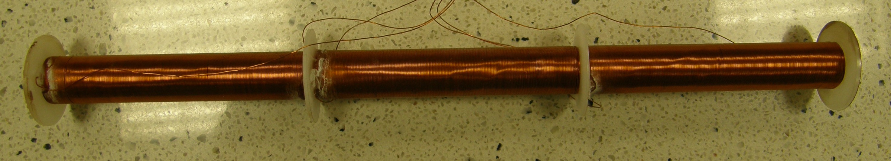
In these instructions I'm going to show you how to make the Linear FCDT we used to detect the Moon with:
![]()
This sensor has a great L/R ratio. It means that it has a really high sensitivity, but it can only measure tilt in a small interval.
(Making a Toroidal FCDT is a little bit more tricky and you'd probably need a glass technician who would bend the glass tube for you.)
The Linear FCDT consist of three coils (2 secondary, and 1 primary), a cell half-filled with ferrofluid, and a signal conditioner circuit.
-
2Step 2
First, let's prepare the cell. It will be a 196 mm long glass tube, inner diameter 6 mm, outer diameter 10 mm.
- Cut the glass tube to size.
- Coat it with a shrinkable, so the coils won't slip when winding them.
- Lathe 4 separator disks to separate the coils from each other; place them to equal distances from each other on the shrinkabled glass tube, and strengthen them to the tube with superglue.
-
3Step 3
It's time to coil! We need 5 layers of 0.25 copper coil for each coil. To make your life easier you can DIY a simple coiling machine like this:
![]()
Or, if you've got access to a lathe, you can use that too. Just strengthen the previously prepared cell to a threaded rod with M6 screw nuts, strengthen the end of the rod to the lathe's chuck, turn on the lathe on small speed, and start winding.
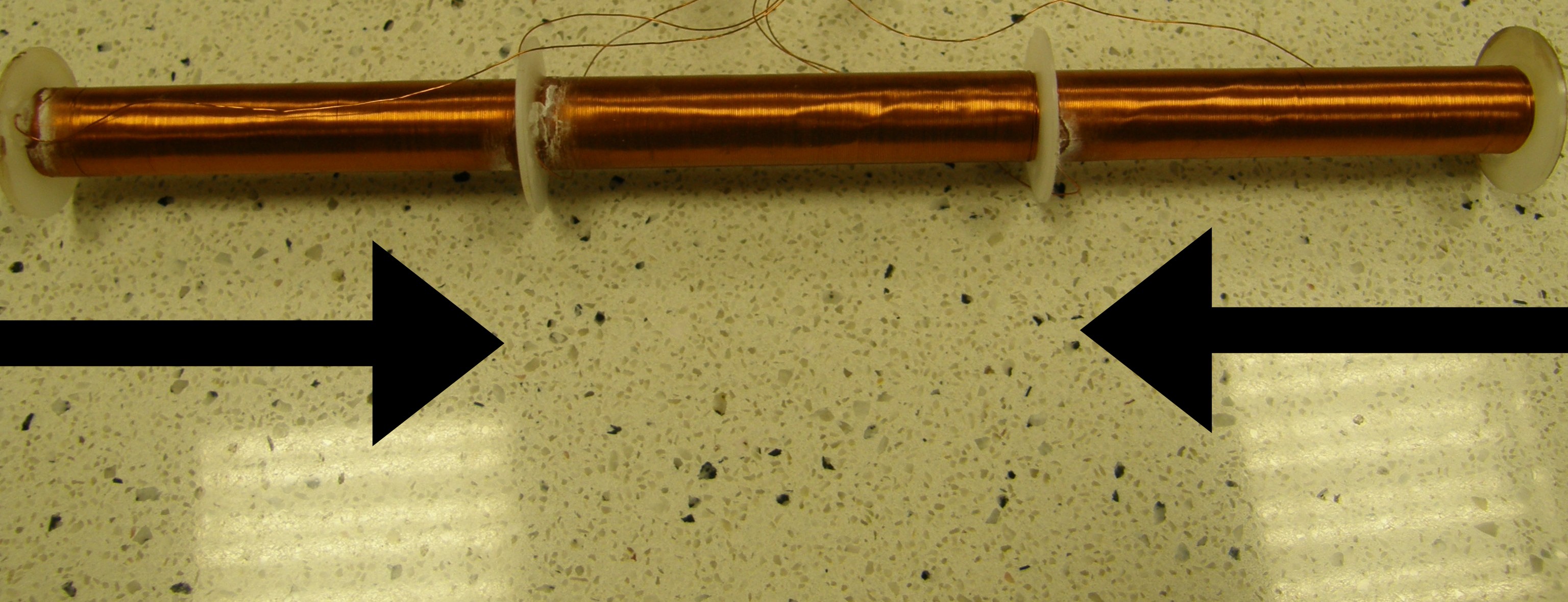
Note that when winding the secondary coils, you have to wind them symmetrically. In the figure below I illustrated the winding direction of the secondary coils:
![]()
After finished with coiling, it's optional to check the resistance of the coils. The secondary coils' resistances' difference should not exceed 0.5 Ohm! My secondary coils had a resistance of 27 Ohm, and the primary had 28 Ohm.
-
4Step 4
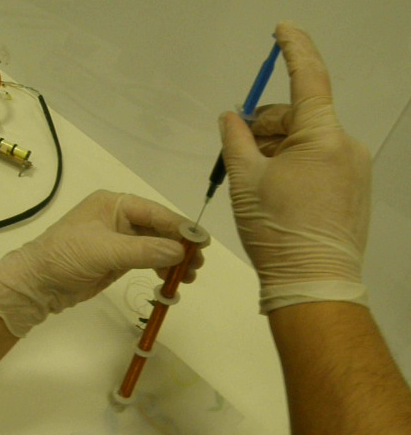
Now we have to fill the cell half with ferrofluid.
- Clean the cell with alcohol.
- Lathe two plugs and stick one of them to one end of the cell.
- Calculate how much fluid do you need (2,77 ml), and fill the cell with that:
![]()
- Stick the second plug to the other end of the sensor.
Finished! :)
-
5Step 5
Last step, signal conditioning.
To make the sensor do something you have to excite the primary coil with an alternating current (normally with sine wave) which has a frequency of 1-20 kHZ and an excitation voltage of 1-24 V rms.
Depending on the tilt degree, the amplitude of the sine wave induced on the secondary coils are changing. To make it understandable for a multimeter for example, we have to turn this amplitude change to a DC output level change. You can use this LVDT signal conditioner solution: http://www.mikesflightdeck.com/lvdts/lvdts.html, but it's circumstantial, it won't be accurate enough (Nevertheless, if you decide to use this method, I uploaded my EagleCAD designs for the circuit to the 'Files' section).
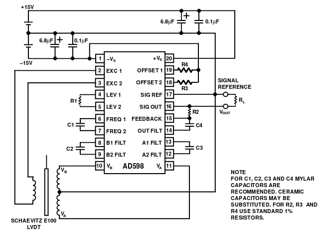
There is a more convenient, and expedient method: using Analog Devices' AD598 LVDT signal conditioner IC. Here are the external parts you need for it (in case you'd like to use a +/- 15V supply):
![]() I took this picture from the original documentation of the IC: http://www.analog.com/media/en/technical-documentation/data-sheets/AD598.pdf
I took this picture from the original documentation of the IC: http://www.analog.com/media/en/technical-documentation/data-sheets/AD598.pdf
A new high accuracy tilt sensor
This project aims to build a tilt sensor that is cheap, very accurate and has a wide measuring range (up to 360 degrees).

 I took this picture from the original documentation of the IC:
Discussions
Become a Hackaday.io Member
Create an account to leave a comment. Already have an account? Log In.