Ever
Ever-
Estimated cost of the project
04/23/2018 at 18:29 • 0 commentsThe Publys platform has among its objectives to be a low cost device, in the design of medical equipment it is difficult to achieve low prices without sacrificing the quality of the device.
In order to build a low cost prototype that I can manufacture without needing to invest a lot of money, I am placing a maximum price of $ 150. I plan to design a PCB whose construction and assembly does not exceed $ 150. This is possible, but it has its drawbacks. I am currently preparing the BOM list carefully, I am using electronic components that are not expensive, I have experience reducing costs, so I apply the criteria I have applied in previous projects.The construction of PCBs should be done in China, so the price will be low. I will choose to assemble the components myself in order to reduce the cost significantly, since in China you must pay from $ 300 for the assembly of at least 5 boards. I have experience with the welding of electronic components, even with encapsulations of type 0603, I must try not to place encapsulations of type 0402 to avoid complicating the assembly.
However, I must send the Stencil in China with the same company that I select to make the PCBs, the cost of the Stencil must be around $ 100.
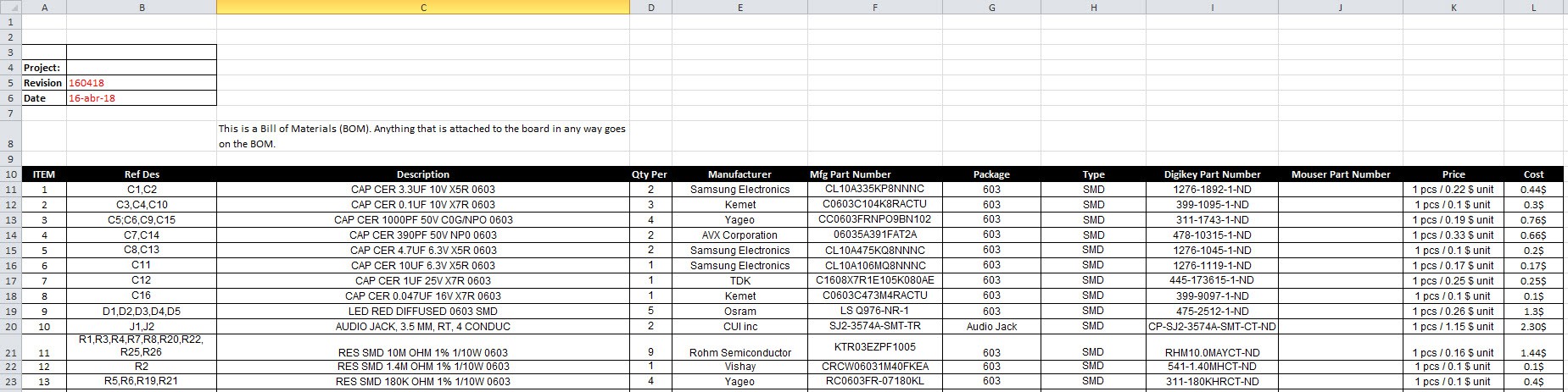
I must take care that all electronic components to be placed on the PCB do not exceed $ 70, since I must buy some parts such as: electrodes, bracelet to measure blood pressure, etc.![]()
Figure 1. BOM preview
I must select a enclosure plastic shell in order to have the lowest possible price.
According to the progress of the project, I will have a real estimate of the cost of the device. I plan to buy the electronic components through Digikey or Mouser, so I must place the part number of both providers.
-
Microcontroller to be used in the project
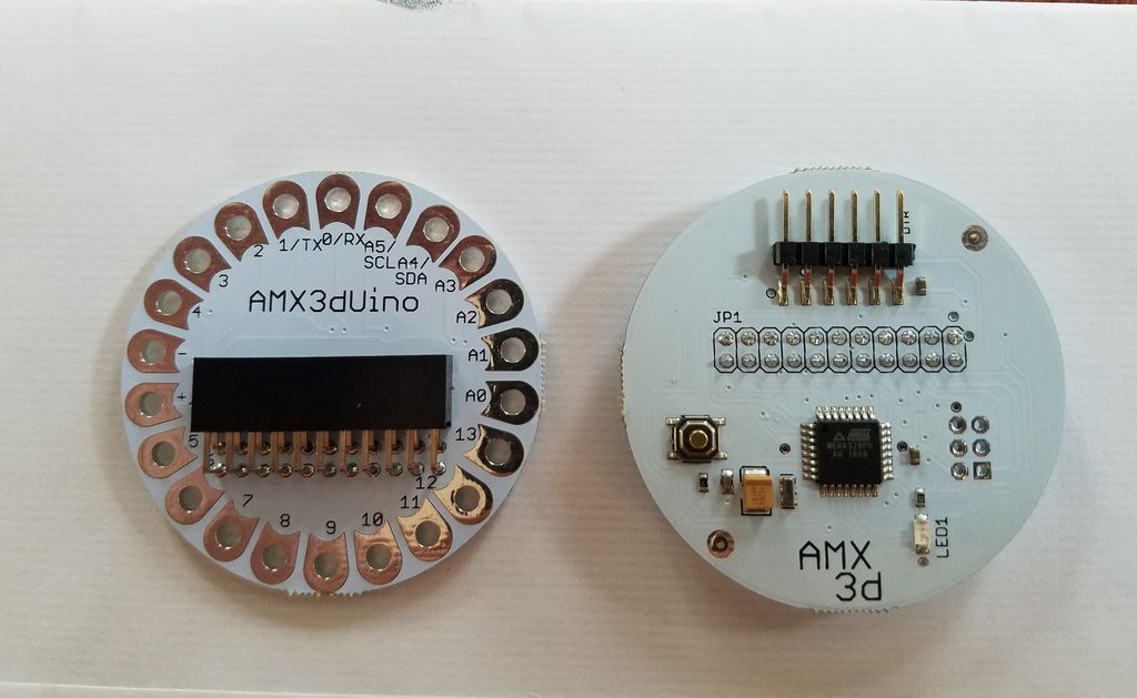
04/22/2018 at 18:06 • 0 comments![]()
The Publys platform in its version V1.0 will use an Atmega328P as a microcontroller, I hope for future versions to replace it with another one of better features and greater security.
The PCB shown in the image corresponds to a custom design made for a company, this has a better with respect to the Lilypad Arduino board. I will use this board because it will allow me to do quick tests as I elaborate each one of the sensors of the project. This will be a way to validate the prototype quickly and without the need to generate high costs in the prototyping phase.
This is a 2-layer PCB, which allows access to all ports of the microcontroller, also can be powered by a 3.7V Lithium battery, this is one of the advantages and allows the device to be portable.In future updates I hope to give new advances in device hardware development.
At the moment I am working on the design of the following sensors, as well as on the design of the feeding stage of the project. -
How can Publys help build hope?
04/21/2018 at 18:59 • 0 commentsThe Hackaday prize 2018 wants us to build hope for a better world, under this premise the Publys project supports its foundations to build an open source platform that benefits society in at least one aspect.
Publys wants to give people the opportunity to venture into science, open the doors to the development of technology that impacts society. People want to cure many diseases, but do not have medical equipment, high costs end up frustrating the wishes of many. I want all researchers to return to the hopes of having development platforms for low-cost medical devices, this is possible and it only takes effort and want to share expertise.
In Latin America there are many talented people with great ideas, but we have very limited resources to develop science and technology. Publys wants to give the opportunity to the development of new ideas in the medical field, we know that there are many great ideas that hope to materialize, but they need a platform that allows to make prototypes quickly and economically. Anyone who wants to innovate and create portable medical devices need to have low cost and high efficiency instruments, I hope this is possible in countries like: Argentina, Bolivia, Brazil, Colombia, Chile, Ecuador, Peru and Venezuela.
I believe that anyone with the desire to help humanity take part of my project and from anywhere in the world can create a new electronic device that improves or takes care of our health.
I have hope in it and I trust that Publys could contribute to the open diffusion of science and technology.
-
Project advances expected
04/18/2018 at 14:20 • 0 commentsFor the moment I have explained the development of the EMG and ECG sensors. In the next few days I will be addressing the development of the other three sensors that the Publys board should carry, which are: Blood pressure, temperature and GSR.
The design of the schematic diagram of the complete project is not finished yet, details are missing to add, I hope to work on it soon and be able to have the complete schematic diagram in less than a month.
At the end of the schematic diagram I must start designing the PCB, apply DFM techniques in order to have an optimized prototype for large-scale manufacturing, however the first prototype will be a bit large (estimated dimensions 100mm x 70mm). For the second prototype the size must be reduced.
For this project I have no plans to design a plastic enclosure since it escapes my knowledge, I will just look for a plastic enclosure to which the PCB can be adapted.I will choose to look for one in the China market. As a future work, I should work on creating a more professional and personalized plastic enclosure, which can highlight the physical aspect of the product to be built.
I hope to talk soon about the choice of electrodes and how they can impact the quality of the signals that are obtained.
This project is divided into 3 parts:Part 1 of this project includes all the hardware design and files for manufacturing. Cover theoretical aspects of the functioning of the device and document the process necessary for manufacturing. Estimated time of work: 2 months. At the moment there is an advance of 40% in this phase of the project.
Part 2: I hope within a month and a half to start phase 2 of the project, which consists in developing all the software that the Publys platform requires for its optimal functioning. I decided to leave it for after having the hardware developed, since for me it represents the biggest challenge of the project, I am not a software specialist, but I understand everything that must be done.
Part 3: Hardware, Software and Mechanical Integration. This is the last phase of the project and must carry a work period of 1 month. Integrating the hardware and software will be done in a simple way. I should spend time getting the plastic mold I plan to use for the device. Subsequently, I must work on testing all the sensors contained in the Publys platform. Estimated time of work: 1 months. At the moment 0% of advances.
I have researched a lot and there are many applications of algorithms based on open source that I can use and I will only need to make adaptations. This is the most experimental part of the project. Some hardware modules I have tested separately and they work. Estimated time of work: 2 months. At the moment 0% of advances.This is the basic structure of the project, as it progresses it may undergo modifications and even extend its range of scope.
My efforts will be focused on designing a portable and low-cost platform that streamlines research for the development of new electronic devices in the E-Health sector. -
EMG sensor
04/12/2018 at 15:22 • 1 comment"Electromyography (EMG) is an experimental technique concerned with the development, recording and analysis of myoelectric signals. Myoelectric signals are formed by physiological variations in the state of muscle fiber membranes." Basmajian&DeLuca: Muscles Alive
![]()
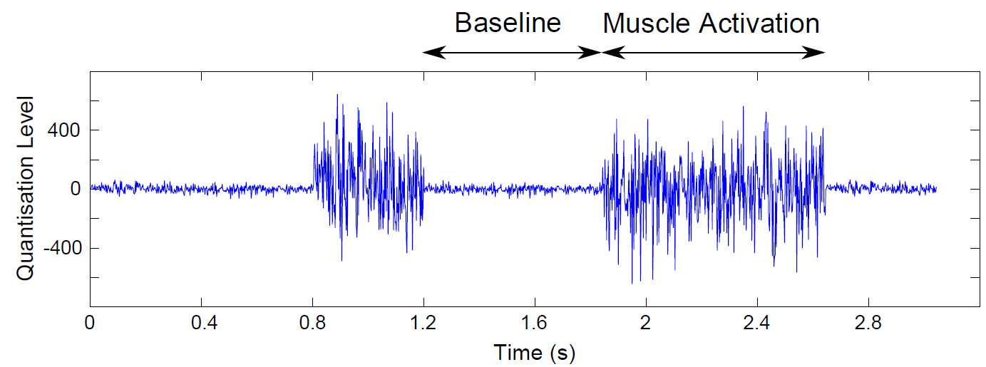
Figure 1. Example of the EMG signal
Besides basic physiological and biomechanical studies, kinesiological EMG is established as an evaluation tool for applied research, physiotherapy/rehabilitation, sports training and interactions of the human body to industrial products and work conditions.
Typical benefits are:
• EMG allows to directly “look” into the muscle
• It allows measurement of muscular performance
• Documents treatment and training regimes
• Helps patients to “find” and train their muscles
• Allows analysis to improve sports activitiesBased on these basic aspects, it is of vital importance to include a low cost sensor to achieve the acquisition of EMG signals on the Publys platform. There are various hardware implementations to acquire EMG signals, but mostly they use operational amplifiers with dual power supply.
Since one of the premises of Publys is to build a device that uses a 3.7V battery, I must use integrated circuits that only need a single power supply, so I opted to use the AD8232 to build the EMG sensor.The EMG signal can be obtained from the motor units of the arm muscles using ordinary EMG surface electrodes. However, the raw EMG signal can not be used immediately, it needs to be processed, it must go through several procedures . To achieve this and deliver a signal that allows at least the movement of a 3D printed prosthetic hand, choose use the AD8232.
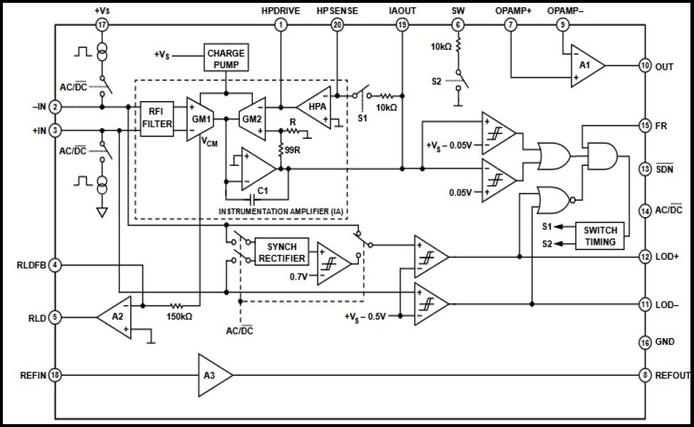
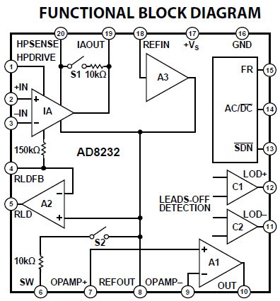
Originally, this integrated circuit is designed for the acquisition of ECG (electrocardiograph) signals and heart rate monitoring. By changing certain components, as will be explained later, this circuit can be used in the acquisition of EMG signal since it shows a high degree of signal extraction, amplification and filtration in noisy conditions, which is the main problem of EMG signals. The internal configuration of AD8232 that aids in the process of signal processing is shown in Figure 2. However, the AD8232 can not provide enough filtration for the EMG by itself. For this reason, several passive components are connected to the chip in a way that makes the overall circuit more effective
![]()
Figure 2. AD8232 inner configuration
As can be seen in the internal configuration of the AD8232 we can identify some key elements such as: an instrumentation amplifier (IA), a operational amplifier (A1), a right leg drive amplifier (A2) and a reference buffer (A3).
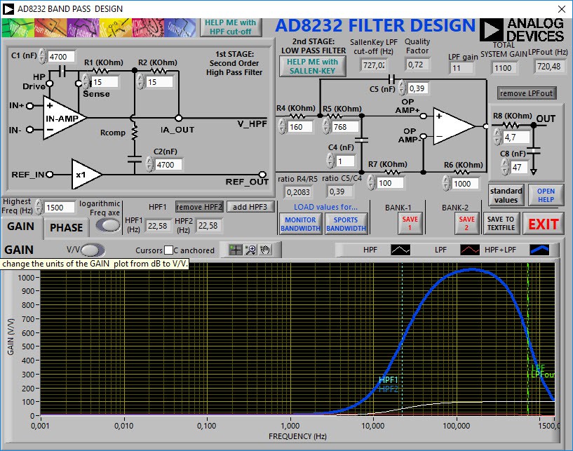
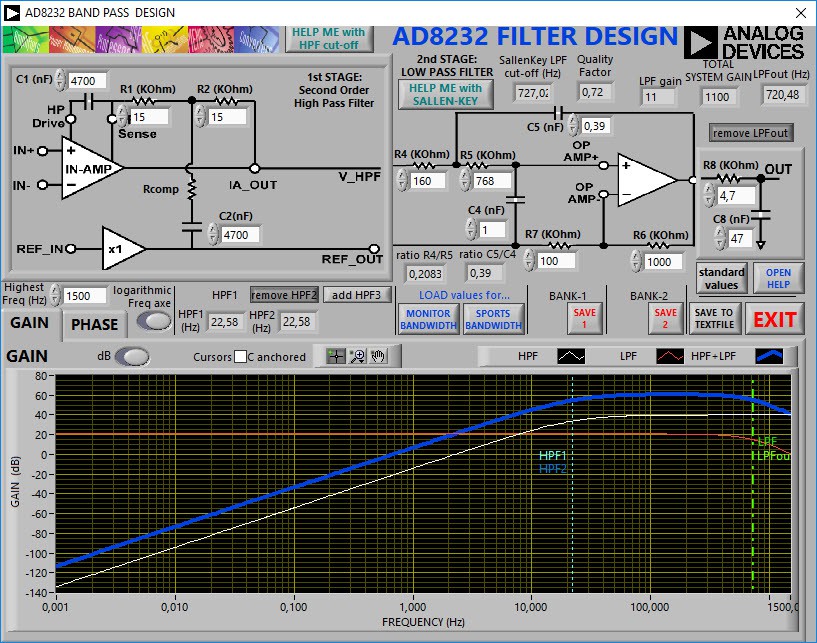
These are the inner connections of the AD8232 chip. The chip must be connected to certain components in order to enable it to perform the required task. The manufacturer suggests a configuration to extract ECG signals, this same configuration can be used to extract EMG signals, but the values of the components must be modified to have different cut-off frequencies than the ECG. Through the AD8232 filter design tool the values of the electronic components were obtained, the figures below show the frequency response.
![]()
Figure 3. Gain in V for EMG signal in AD8232
![]()
Figure 4. Gain in dB for EMG signal in AD8232
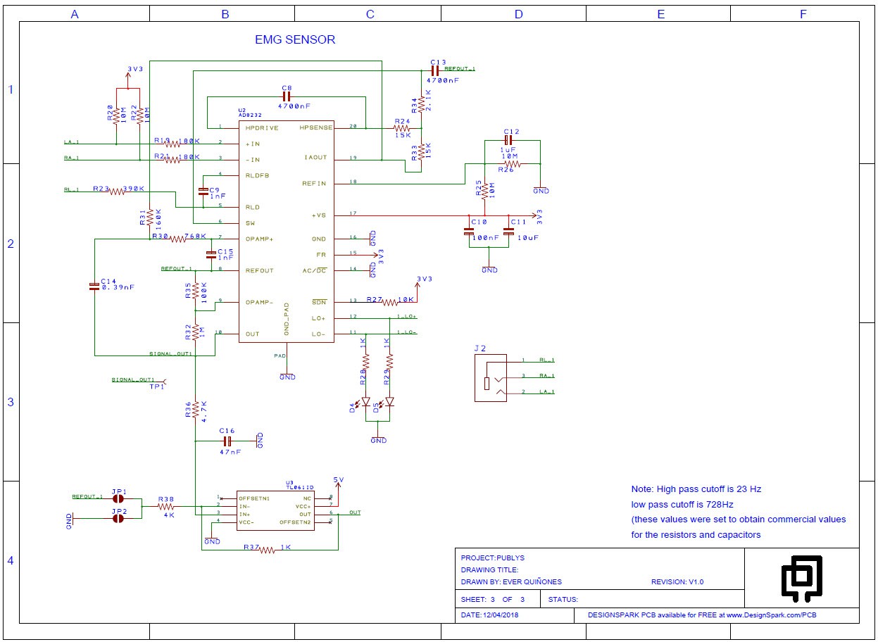
The obtained values will allow to configure the AD8232 as a sensor that allows to extract EMG signals in the range of 20 Hz to 730 Hz. This range was considered because it represents the maximum power of the EMG signal and allows to obtain electronic components with commercial values and easy access. The circuit shown in figure 5 contains the configuration for the EMG sensor.
![]()
Figure 5. EMG sensor
After extracting the EMG signal it is necessary to send it to the channel of an ADC to later enter the Atmega328P microcontroller. As an application of the Publys platform, it is expected to be able to use these signals to generate motions in servomotors and to be able to implement 3D prototype prototypes in the future. This is one of the functionalities that Publys proposes in the long term.
-
Biosensing for the human body
04/02/2018 at 20:28 • 0 commentsThen proceed to explain each of the modules responsible for acquiring the different bioelectric signals to be sensed.
Sensor 1: ECG
“The ECG signal is one of the most important biosignals that can provide a great amount of information in medical and fitness applications. It senses the electrical activity of the heart during its muscular contractions. During the heartbeat, the muscular cells on the hearth surface depolarize their membrane. The resulting potential differences can be detected using surface electrodes placed in a proper configuration and a low noise signal amplifier. The typical frequencies of ECG signals go from 0.01 to 250 Hz and the amplitude is lower than 5 mV” (S.Benatti, B.Milosevic, M.Tomasini, E.Farella, P.Schonle, P.Bunjaku3, G.Rovere, S.Fateh, Q.Huang, L.Benini)
There are multiple ways to acquire an ECG signal, for this device choose to use the AD8232 chip which has great advantages and can also be powered with a voltage of 3.3V.
The AD8232, from Analog Devices, is a conditioning IC for applications of ECG measurements and other biopotentials. It is designed to extract, amplify and filter the small bioelectric signals in the presence of conditions of noise.
The AD8232 has the ability to implement both a high-pass filter of two poles, as well as a three-pole low-pass filter for the elimination of noises; for this it has internal amplifiers elements attached to the architecture of the instrumentation amplifier. Also, to improve the CMRR, it has a special amplifier for the reference measurement (right leg).
Some technical characteristics of the AD8232 are:
- Supply voltage: 3.3 VDC
- CMRR of the instrumentation amplifier: 80dB
- Gain of the Instrumentation Amplifier: 100
- Input impedance in differential mode: 10GΩ
- Operating temperature range: [-40, 85] ° C
- It has a spectral noise density of 100nV for F = 1KHz, 12uV for F = 0.1Hz at 10Hz, 14uV for F = 0.5Hz at 40Hz and a differential voltage of up to 300mV.
![]()
Figure 1. Functional block diagram.
The acquisition of the ECG signal is essential to diagnose abnormalities cardiac. The electrical signal of the heart has very strong characteristics and an accurate acquisition system covering all the peculiarities of the ECG signal should be designed.
The first is that the ECG frequency is between 0.05 and 100 Hz, sometimes up to 1KHz. Since the signal is very weak (approximately 1 mV peak-to-peak), it must be amplified. Besides, the instrumentation must have a high capacity to reject common mode (CMRR), normally in the range of 80 to 120 dB. To prevent small ECG signals are loaded on the skin, the ECG must have at least 10 MΩ impedance entry (Webster, Volume 3, 2006, 40-41).Design Implementation:
The circuit for the acquisition, digitalization and transmission by Bluetooth of the signal consists of 3 electrodes connected to an analog front-end, this will filter and amplify the signal, a 12-bit ADC (ADS1015) and the Atmega328P that takes the signal coming from the ADC and it processes it through a set of algorithms. The communication between the board and a PC will be given thanks to the bluetooth that must be incorporated into the platform.
The AD8232 passes the signals to Atmega328P which then processes it and displays the RT waveform on the PC display.
The instrumentation amplifier that incorporates the AD8232, has a CMRR of 80 dB for a frequency range between 0 and 60 Hz (which, therefore, includes the line frequency). The input impedance is 10 G. The typical polarization currents are 50 pA, and the input offset current is 25 pA. The internal gain of the amplifier is 100.
Within this stage, an amplifier is included that allows a high-pass filtering and eliminates the direct current. This allows to eliminate the offsets of the electrodes of up to 300 mV, and also low frequency signals such as the deviation of the baseline. By connecting an RC network between the output of the instrumentation amplifier and the inverting input of the HPA amplifier, an integrator is formed that feeds back the low frequency signals to the instrumentation amplifier, eliminating them without saturating any node and maintaining the gain. Depending on how external resistors and capacitors are connected, a high-pass filter of one, two or three poles can be achieved. A greater number of poles improves the rejection to the noise of low frequency, but as a counterpart it produces a greater distortion of the signal and requires a greater number of components. In the case of the Publys plate, the filter is of two poles. In the AD8232 data sheet, some design recommendations are offered regarding the values of the resistors and capacitors that make up the filter.
Frequency Response
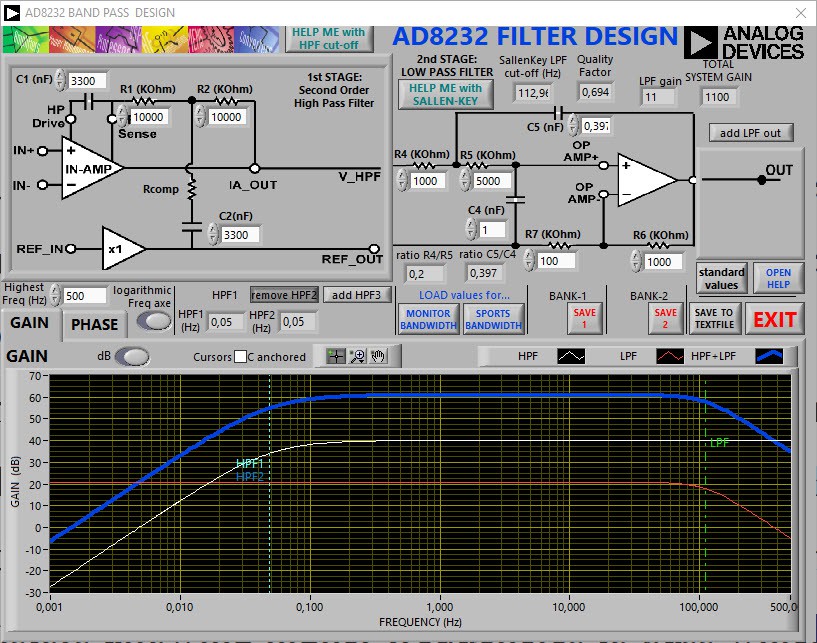
Standard –3dB frequency bandwidthfor patient monitoring is 0.05Hz to 30Hz, while diagnostic grade monitoring requires 0.05Hz to 100Hz or more. The analog front end must be AC coupled to remove artifacts from the electrode offset potential.The upper and lower cut-off frequency of the system was adjusted to 0,05 Hz and 113 Hz, respectively.
To perform the calculation of the respective cut-off frequency, the tool was used: AD8232/AD8233 Filter Design Tool
This tool is super useful to define the lower and upper cut-off frequency. The datasheet recommends using several formulas to establish them, but care must be taken with the Q factor of the filter. I have experimented enough with the AD8232 and at first I only worked with the formulas, but I lost a lot of time doing the calculations and the Q factor used to leave the range between 0.5 and 0.7, this led to many times the ECG signal is saturated and is not possible to visualize it.
By starting to use the filter design tool, I was able to play with the value of the components and the Q factor to my liking, avoiding expenses and reducing design times.
The setting of the cut-off frequency higher than 113Hz instead of 100Hz is due to the values of the components, if adjusting the cut-off frequency of the filter at 100Hz would have non commercial component values.
Then I show screenshots of the design of the filters, and additionally the tool allows me to visualize the bode diagram of the output signal.![]()
Figure 2. AD8232 filter design gain in dB.
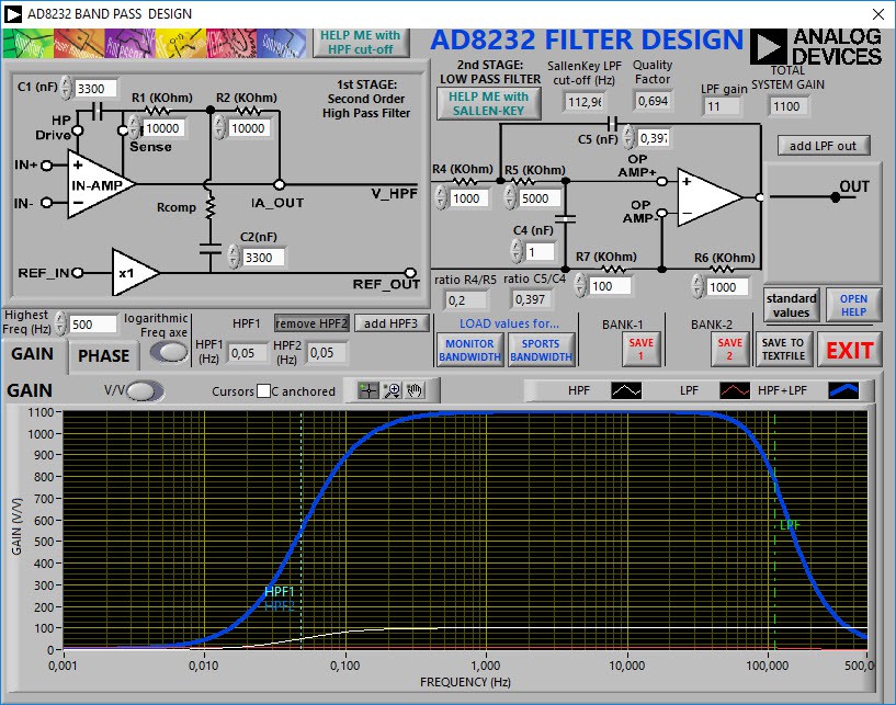
The ECG sensor will have a gain of approximately 1100, this is due to the value of the resistors R6 and R7 in the following figure.
![]()
Figure 3. AD8232 filter design gain
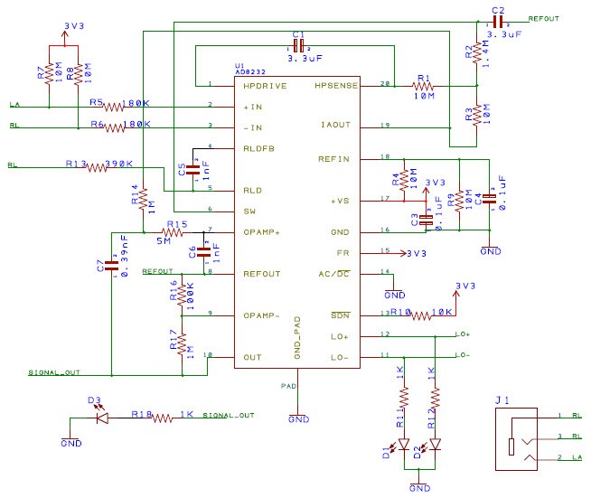
The schematic diagram of the ECG sensor is placed below.
![]()
Figure 4. ECG Sensor.
Note: This configuration of the ECG sensor is fully functional, I have had the opportunity to verify it in real tests and it has a very low noise level. Then I will place the images and explain some factors to take into account to optimize the ECG signal.
Publys: An open source biosensing board
Publys is an open source platform for the study and processing of bioelectric signals.