Ozan Enginoglu
-
Step 1 - Encoder
05/23/2016 at 12:43 • 0 commentsIn this step, it is aimed to connect the encoder (just encoder not the dc motor) to the Arduino and check if it is functioning properly. We know that the encoder output for the gearbox shaft's only one turn should return 1920 so we will be checking that manually by rotating the shaft of the motor by hand.
![Encoder]()
Luckily, pin diagram of the encoder is given on the pololu web site as shown in the table below.
Color Function Red motor power (connects to one motor terminal) Black motor power (connects to the other motor terminal) Green encoder GND Blue encoder Vcc (3.5 - 20 V) Yellow encoder A output White encoder B output Motor power pins won't be used in this step but the other four pins are necessary for the encoder to function properly. Encoder GND and Vcc pins are used to power encoder circuit and encoder A and B pins are used to get feedback from the encoder. Green encoder GND will be connected to Arduino's ground pin and Vcc pin will be connected to Arduino's +5V regulated voltage output which is within the range (3.5 V - 20 V).
While connecting Encoder Pins A and B, it is important to select the pins that can be used for interrups. The reason for using interrupt pins is that Arduino should be able to get the feedback data from the encoder as soon as it changes. If the interrups are used Arduino will be able to stop whatever it's doing at that moment and get the encoder feedback first and continue. After a short search, i was able to find the table shown below.
Board Digital Pins Usable For Interrups Uno, Nano, Mini, other 328-based 2, 3 Mega, Mega2560, MegaADK 2, 3, 18, 19, 20, 21 Micro, Leonardo, other 32u4-based 0, 1, 2, 3, 7 Zero all digital pins, except 4 MKR1000 Rev.1 0, 1, 4, 5, 6, 7, 8, 9, A1, A2 Due all digital pins In this project I'm using Arduino Mega2560 so the pins i can use are 2, 3, 18, 19, 20, 21. Among these I preferred 18 and 19. So I connected encoder output A to digital pin 18 and output B to digital pin 19.
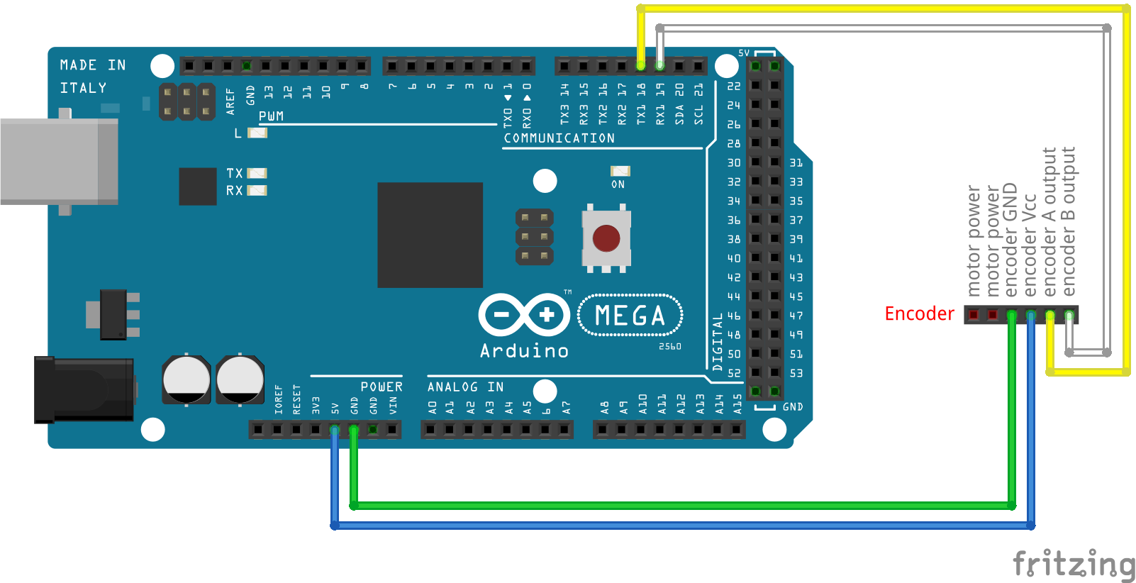
Pin connections of the encoder are shown in the Figure given below. As can be seen in the figure, motor terminal connections are intentionally left blank.
![Encoder Connections]()
-
Fundementals
05/23/2016 at 12:41 • 0 commentsStandard DC motors without encoders have just two cables (terminals) to drive the motor. These terminals are used for creating a voltage difference which is directly related to motor speed. The shaft rotation speed is increased if the voltage difference between terminals are increased or vice versa.
By inverting the applied voltage to these connections, it is possible to drive the motor in the opposite direction. But unfortunately, the relation between the applied voltage and the speed is not linear and the output of the shaft rotation is unpredictable due to various reasons such as a torque applied to the shaft. In such case shaft rotation speed is reduced even though the voltage stays same. So it is clear that the speed of the motor doesn't only depend on the voltage but also to the environmental conditions.
If speed control of a DC motor is desired, another sensor called encoder is required to get the actual position and thereby speed of the shaft rotation. These information is then used to compare and if necessary correct the speed of the dc motor.
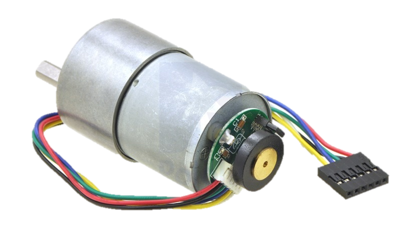
Pololu DC motor with Encoder that i've used in this project is as shown in the picture below.
Full Name: 30:1 Metal Gearmotor 37Dx52L mm with 64 CPR Encoder
![Pololu DC motor with Encoder]()
This motor has a metal gearbox with a ratio of 30:1 and a shaft with a diameter of 37 mm. Resolution of the encoder that is assembled to the motor shaft is 64 Cycles Per Revolution (CPR). This means that if the motor shaft turns one round the output of the encoder counts up to 64. But it is important to notice that the gearbox shaft is different than the motor shaft and as mentioned before, the ratio of rotation between these shafts is 30:1. So if motor shaft turns 30 times, gearbox shaft turns just 1 time. If this relation is considered; the cycles per revolution of the gearbox shaft can be calculated with the following formula:
and it is equal to 30 * 64 = 1920 CPR.
The gearbox output resolution (1920 CPR) is of great importance in this project because it is the only feedback we get from the DC motor and using this feedback we shall acquire position and speed variables to be used in PID control which will be explained in detail later.
Just like almost all complex projects, we should always prefer going through the project step by step to prevent any unknown behaviour output from the system. For this project, the steps i am planning to follow are listed below.
- Encoder
- DC Motor + Motor Driver + Encoder
- PID + DC Motor + Motor Driver + Encoder
DC Motor Speed Control with PID
In this project it is aimed to speed control a standard Pololu DC motor with encoder using software based PID controller.