Close
0%
0%

Robotic Hand With Interchangable Gripper Types

A robotic hand design that can change the positions of its fingers to achieve better dexterity

Public Chat
Similar projects worth following
This project (RHIG) aims to improve both strength and flexibility of a gripper by designing a bionic gripper with certain fingers that can be positioned on a circular axis without losing the ability to move the fingers. This is achieved by using two extra servos to rotate three of the five fingers, with two points of rotation. So when extra grip force is required, the ring and pinky fingers can rotate 180 degrees in order to turn the hand into a two fingered gripper. Or all three fingers can rotate in order to create a three fingered gripper. With this design, the gripper can be adjusted according to the job at hand - instead of having to work with complicated movements or to compromise one attribute for another - giving the robot extra flexibility and dexterity.

 Our hands are quite the feat of engineering as they can maximize flexibility and strength at the same time with regards to their fibrous, flexible muscle structure. And as most of the tools used in daily life and industrial work are designed to be used by humans, the already built system is a perfect working ground for human hands. But due to the vulnerability of human flesh to hazardous materials and pointy things, there are jobs that are ought to be done by an inhuman structure - such as lifting a pile of rocks or closing shutting down nuclear reactors that went through a nuclear core meltdown.

 Several robotics research groups across the globe are working to create the ultimate inhuman structure – also widely known as robots – in order to minimize the risk, the robots can easily take for a human. But due to aforementioned already built system being built around the general design of a human hand, they have to design their robots with regards to this premise. And this situation leads to grippers not being flexible or strong enough for the purpose, by favoring one gripper type over the other as materials such as aluminum or plastic, which doesnt have the attributes the human flesh has. Most researchers use a three fingered gripper design as a hybrid of a human hand and an industrial two-fingered gripper design. This results in the design being moderate in both flexibility and strength.
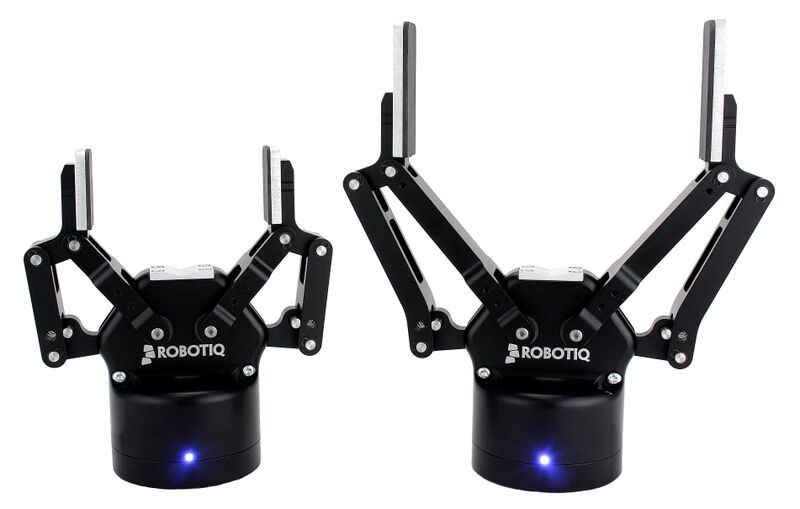
Two fingered gripper design, mostly used in industrial workspaces (Credit: Robotiq)
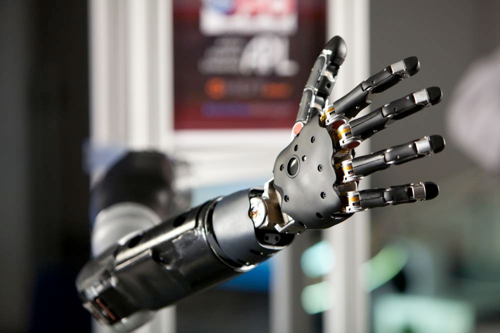
Bionic hand, used in prosthesises and experimental search and resque robots (Credit: DARPA)
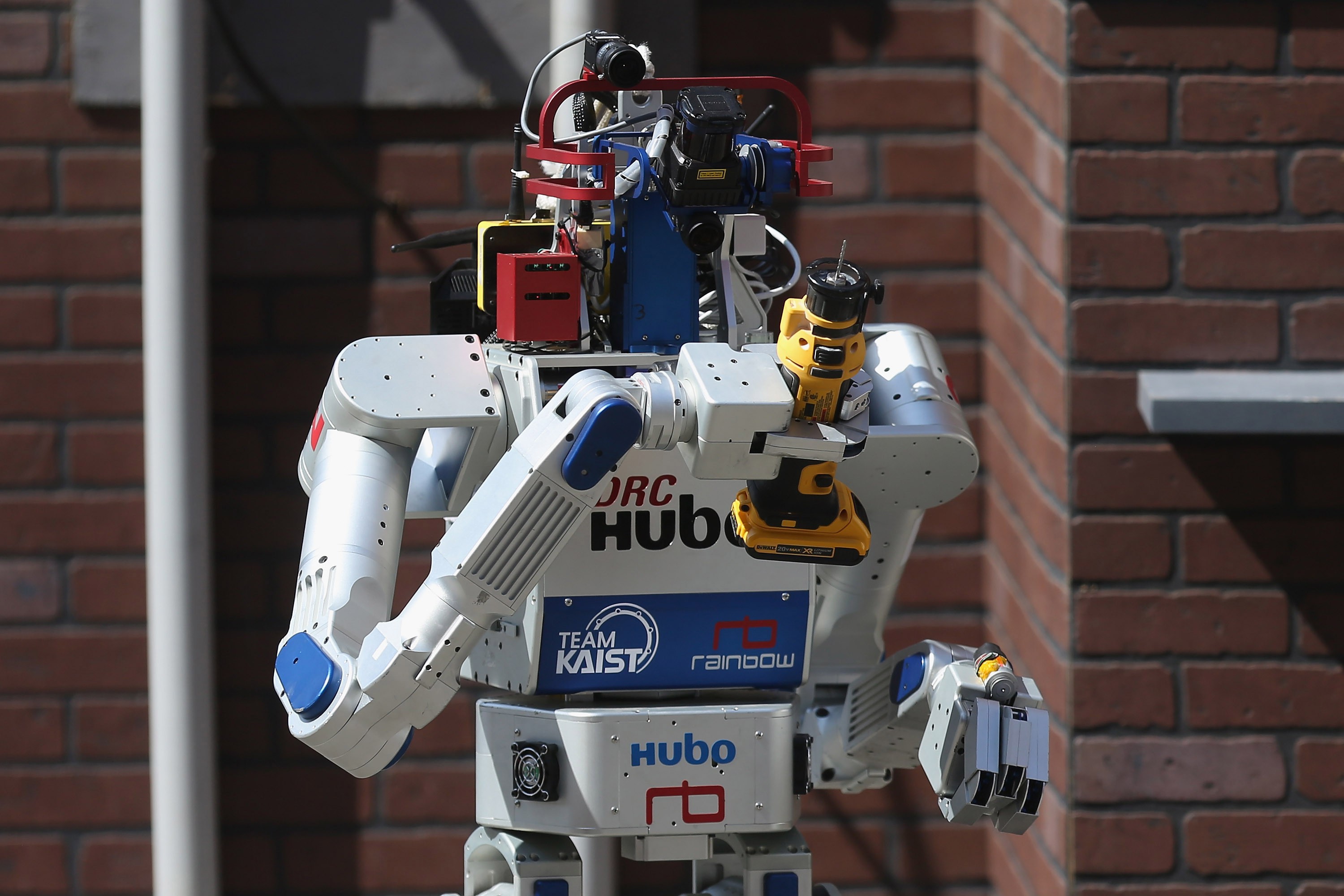
DRC-HUBO of Team KAIST, winner of the 2015 DARPA Robotics Challange

 As seen in the picture above, the hybrid three fingered grippers have to work around the tools that are designed by humans, for humans. This results with robots having to do complicated movements to hold a tool with a grip which is ultimately unnatural. With the use of Robotic Hand With Interchangable Gripper Types (RHIG), robots and teams can tackle the task at hand with a more natural approach as their designs can mimic human movements better.

 All the parts – excluding the servos, screws and the bowden cables – can be printed on a desktop 3D printer, making RHIG easy to produce. And as the only extra parts that differentiate this project from a bionic hand is only two servo motors, RHIG is also cheap to produce.
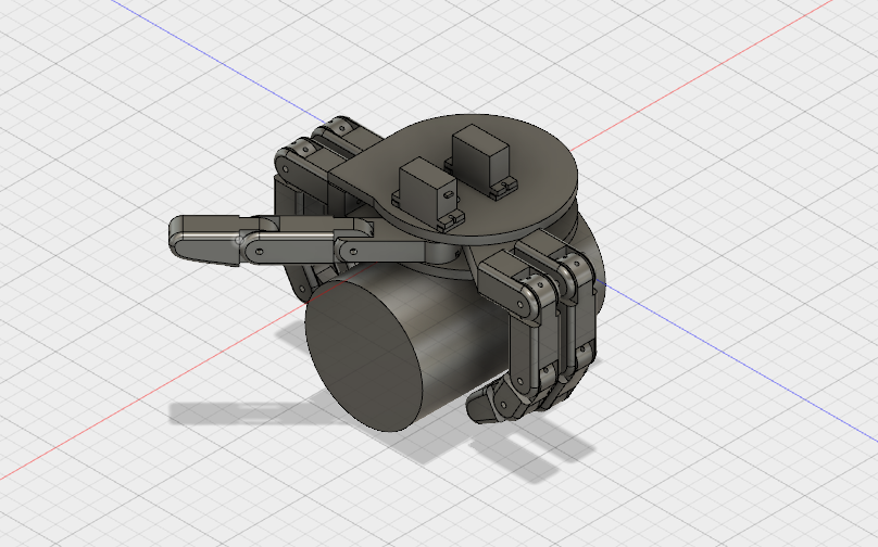
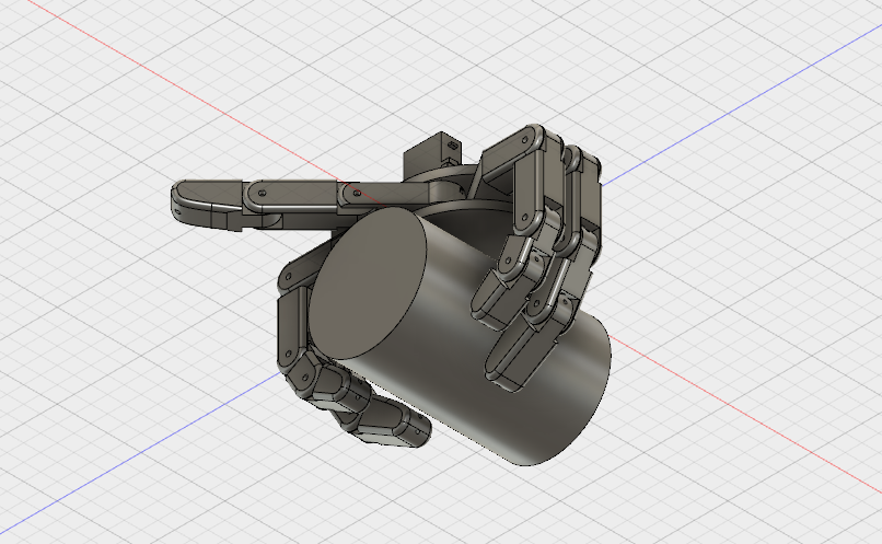
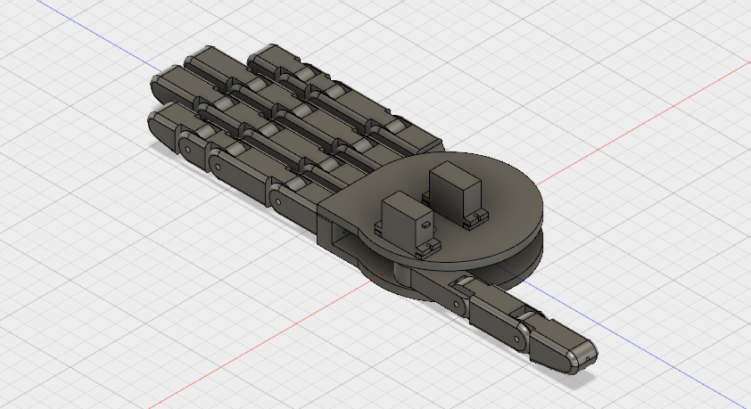
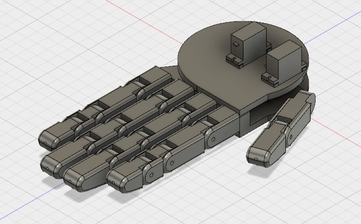
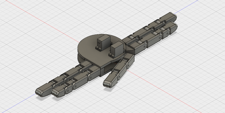
 The usage of the the better grip mode can be seen in the screenshots of the 3D design file above. In order to improve upon this design the finger lengths can be adjusted. And also, the thumb can be implemented in this mode as well to use it as a three finger gripper.

  Due to not having access to a 3D printer, a physical first prototype will not be made for the time being. Although as the 3D design files will be accessible, if you have the tools required, you are welcomed to make one for yourself!
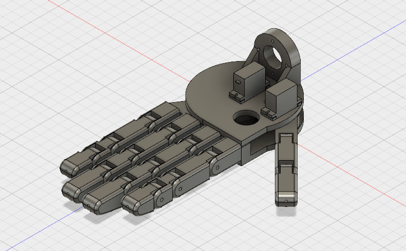
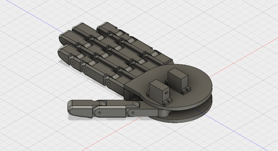
finger connection.stl

Standard Tesselated Geometry - 459.26 kB - 04/23/2018 at 21:52

Download

top plate.stl

Standard Tesselated Geometry - 194.22 kB - 04/23/2018 at 21:52

Download

40mm finger.stl

Standard Tesselated Geometry - 423.52 kB - 04/23/2018 at 21:45

Download

20mm fingertip.stl

Standard Tesselated Geometry - 589.44 kB - 04/23/2018 at 21:45

Download

30mm fingertip.stl

Standard Tesselated Geometry - 556.72 kB - 04/23/2018 at 21:45

Download

View all 11 files

  • 1 × Arduino Mega A microcontroller that can control all 7 servos
  • 2 × Micro Servo The 9g micro servos that are responsible for rotating the fingers
  • 5 × Servo The servos that actuate the fingers
  • 15 × M3 screws Screws required to assemble the gripper (extra 4 more to mount RHIG to something else)
  • 10 × Bowden cable The cables that transmit the mechanical force to the fingers in order to move them

  • Mounting bracket and routing holes

    Oğuz Salar04/22/2018 at 23:43 0 comments

      The modifications necessary to mount the gripper to an existing robotics project has been made. It can be mounted using 4 M3 screws. The servos that are attached to the fingers with bowden cables need to be mounted to the existing project according to the design of the project. For example, for a humanoid search and resque robot, the sensible placement would be the elbow in order to shorten the bowden cable length, making them more efficient. Also cable routing holes have been added to the design in order to make the connection of the bowden cables easier.

      The design of the first prototype of Robotic Hand With Interchangable Gripper Types (RHIG) is finished with these modifications. As mentioned before, i won't be able to physically produce the prototype. All the files will be available, also as mentioned before.

    Final design of the Robotic Hand With Interchangable Gripper Types (RHIG) with the mounting bracket and routing holes

  • Improved thumb design

    Oğuz Salar04/17/2018 at 23:29 0 comments

     The thumb swivel point has been altered in order to increase the degrees of rotation of the thumb. With this alteration, a new and necessary axis of rotation is added to the overall gripper that enables the gripper to do more intricate actions such as pinching.

    The second version with more linear thumb swivel point, extending the range of motion and the gripper's abilities

    Thumb piece rotated for pinching motion

     As the project takes its final shape, the 3D design file will be uploaded with the improvements.

  • CAD model progress

    Oğuz Salar04/12/2018 at 22:40 0 comments

    Basic outline of the CAD model is mostly finished. The fingers will be moved with a two-wire bowden cable system (chosen for their flexibility and ability to transmit mechanical force) which can effectively move the fingers in both direction - by pulling them from either up or down and forcing them to bend - without having to rely on springs to pull the finger back to default position. This also means the fingers actually keep their positions whenever the servos are not being rotated.

    The fingers on their default position (Not final version)

    The fingers on the high torque position (Not final version)

    The remaining features to be added are;

    - Improved thumb connection piece

    - The management of the wires that actuate the fingers

  • Basic sketches and cardboard model

    Oğuz Salar04/02/2018 at 23:15 0 comments

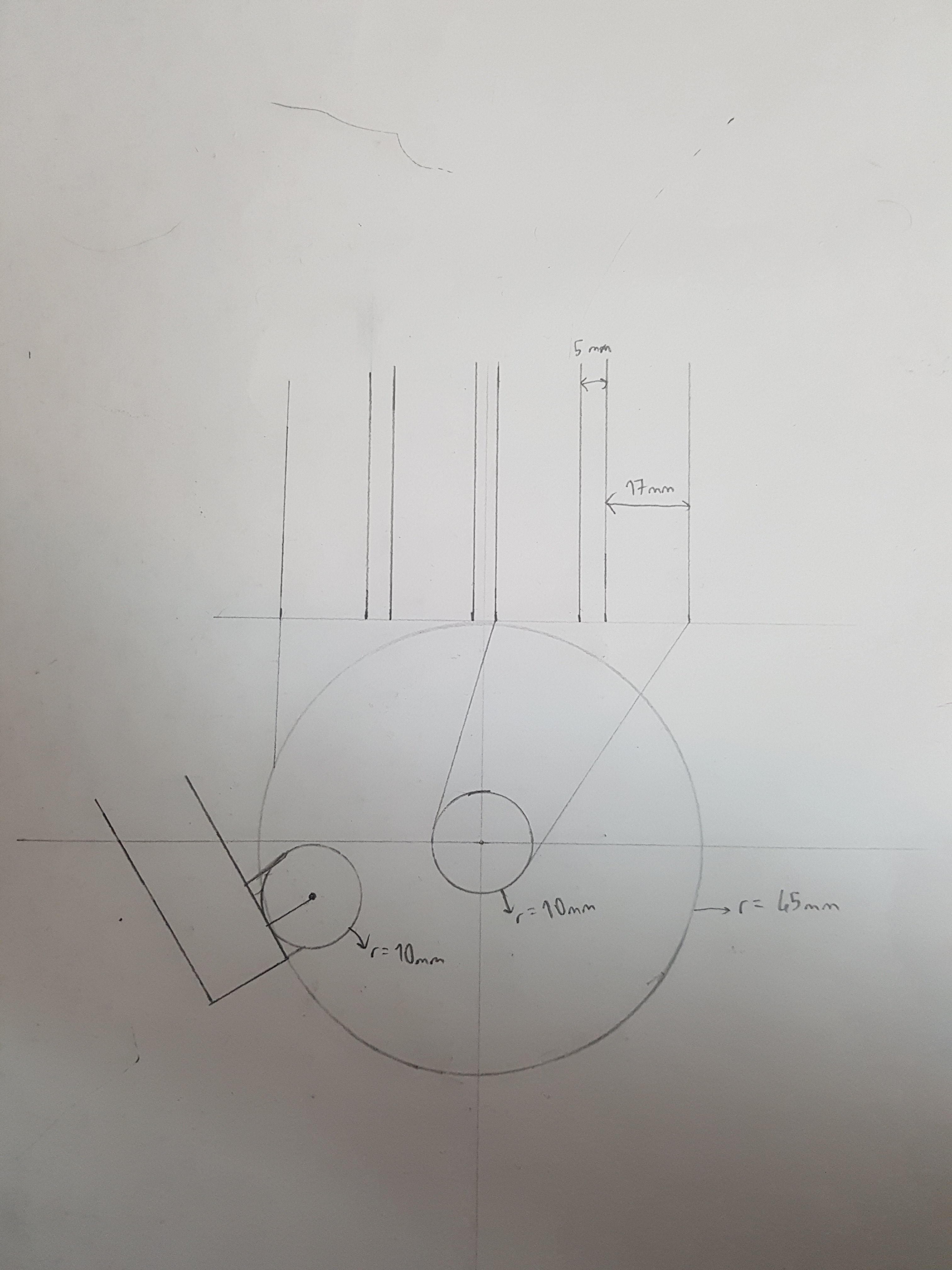
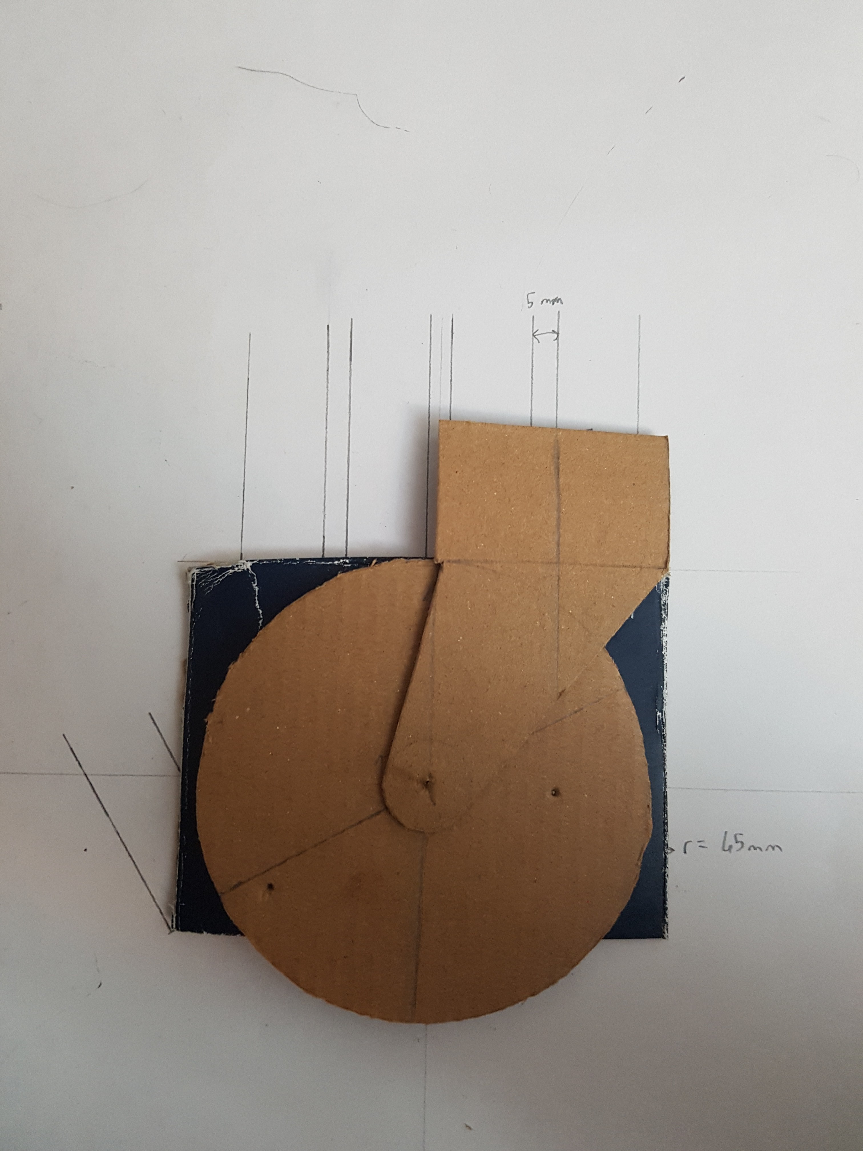
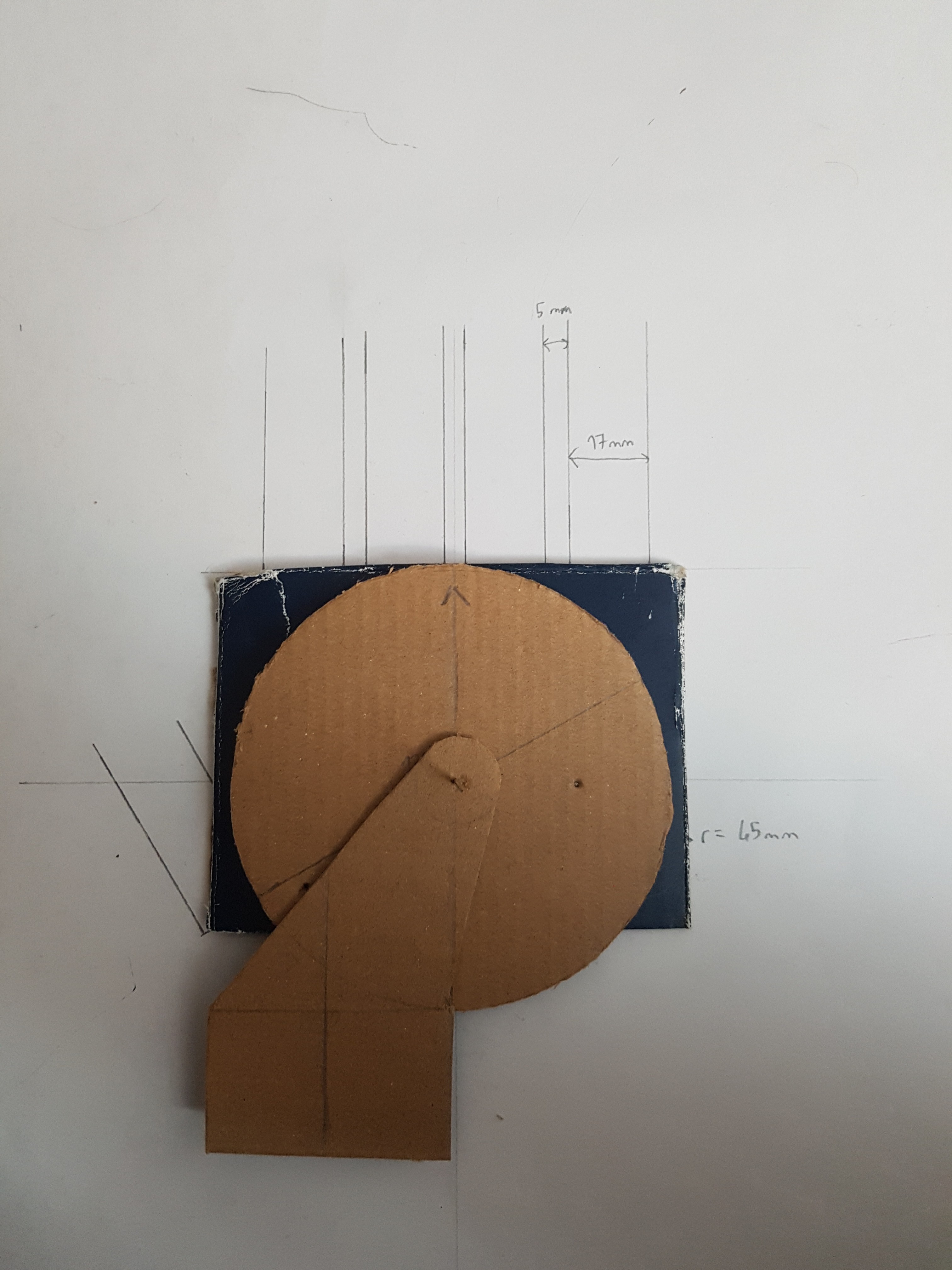
    In order to create the 3D model easier later on, I sketched the basic shapes and measurements and also cut out a cardboard model to make sure the fingers could move as I wanted them to.

    The basic measurements of the gripper can be seen in the picture above. The center of the 10 mm circles will be attached to the servos and will work as a point of rotation. I might need to alter the measurements in order to make the pieces fit better together.

    The cardboard cutout that shows to intended movement of two of the three fingers that will be able to rotate around a total of two axis.

View all 4 project logs

  • 1
    Pieces

    3D print the necessary pieces according to the instructions file.

  • 2
    Assembly of fingers

    Assemble the fingers using M3 screws on the joints and thread the bowden cables through the holes in the middle of the finger pieces. Glue the index finger and middle finger to the "bottom plate" piece; the ring finger and little finger to the "arm" piece, keeping the guidance holes in mind.

  • 3
    Top plate and servos

    Connect the two micro servos to the "top plate" piece with the included screws making sure the middle of the servo in the middle servo bracket is indeed in the center of the circle and the other one is reversed.

View all 5 instructions

Enjoy this project?

Share

Discussions

Similar Projects

Does this project spark your interest?

Become a member to follow this project and never miss any updates