Swaleh Owais
-
Building Conveyor Belt Pt. 2: Motorizing System
04/07/2018 at 21:09 • 0 commentsI have attached a motor to the front roller. This task contained two components: Physically attaching the motor to the axle and implementing a controller for the motor.
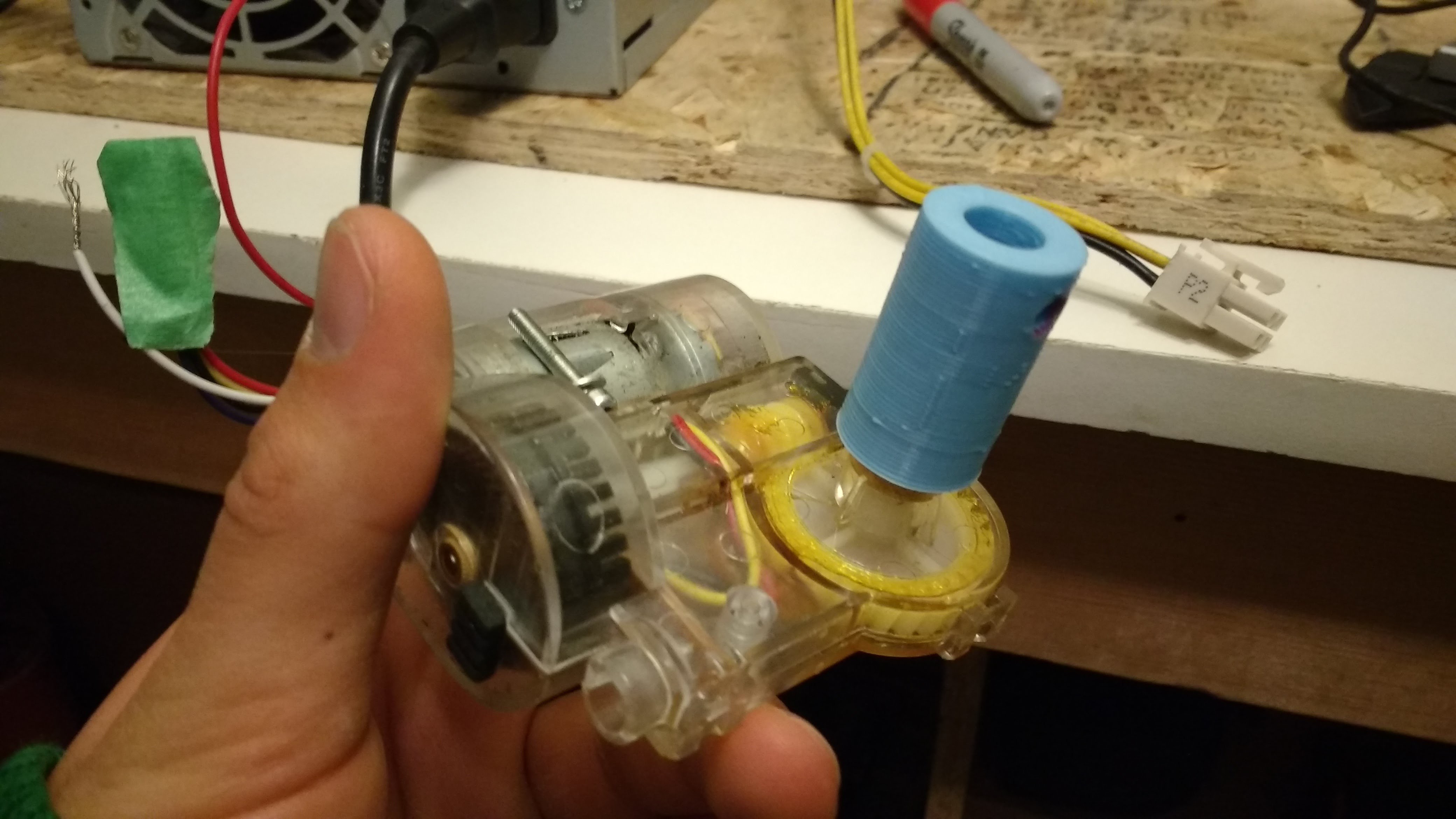
I upcycled the motor from an old robotic vacuum. The motor is a simple 12 V DC motor. The motor had an integrated optical sensor, but I was too lazy too incorporate this into my mechanism.
[Figure 1: Motor Salvaged from bObsweep Robotics Vacuum]
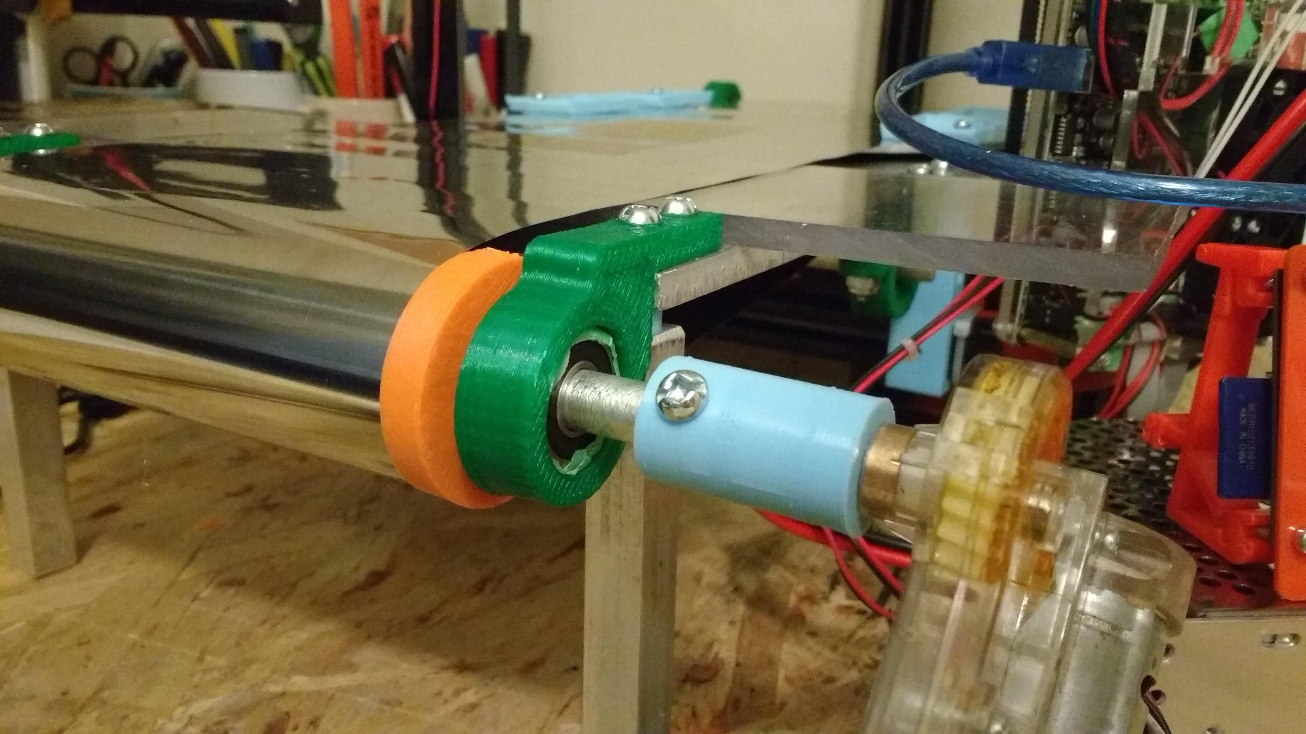
I designed a simple adapter that connects the motor to the front axle. I connected the motor to the axle and then I designed the mount that connects the motor to the bed. This order ensures that the motor axle is concentric to the roller axle.
![]()
[Figure 2: Axle Adapter Attached to Motor-]
![]()
[Figure 3: 8-32 Hole for Adapter]
![]()
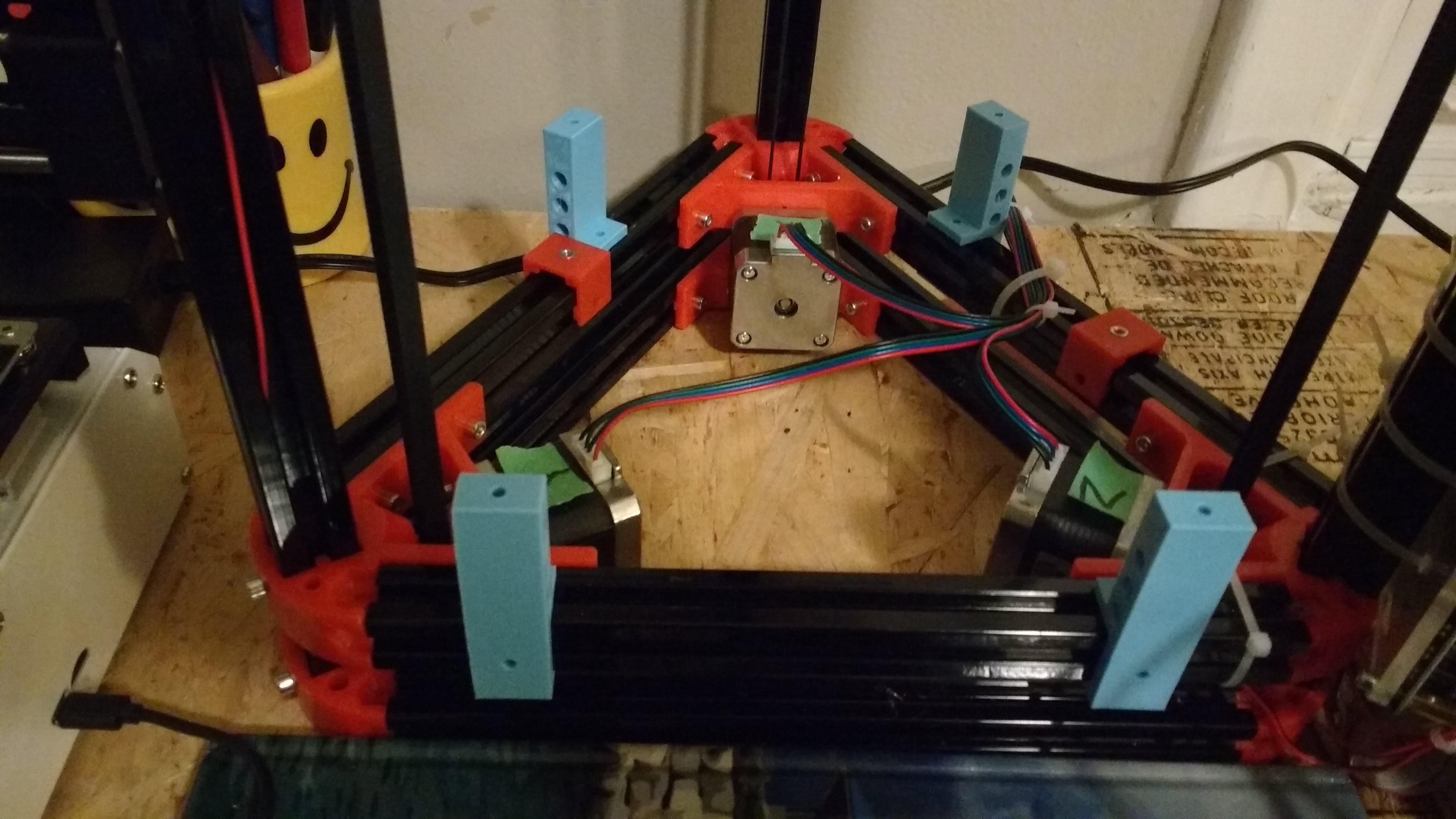
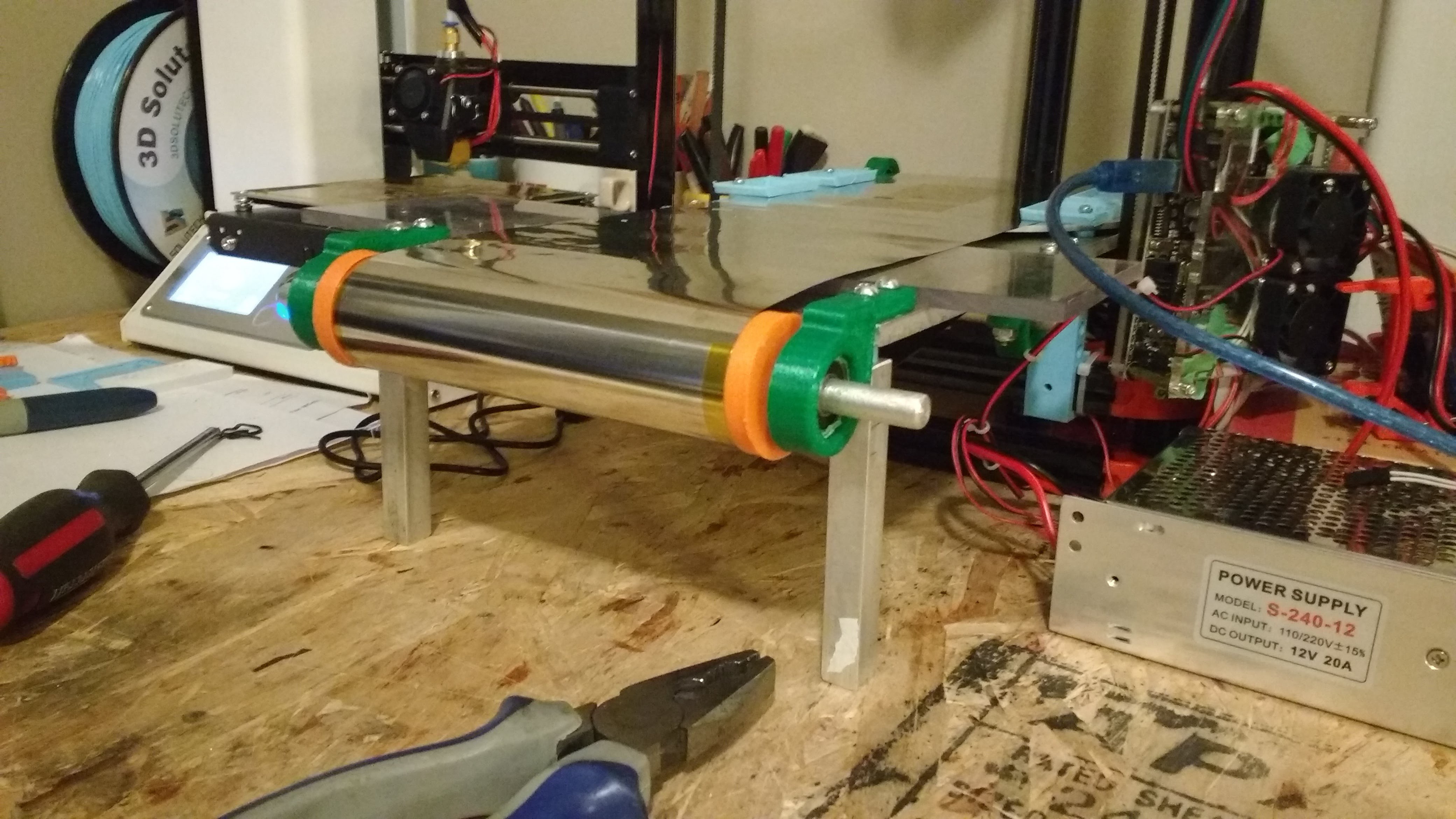
[Figure 4: Motor Connected to Front Roller]
![]()
[Figure 5: Motor Secured to Bed with Motor Mount]
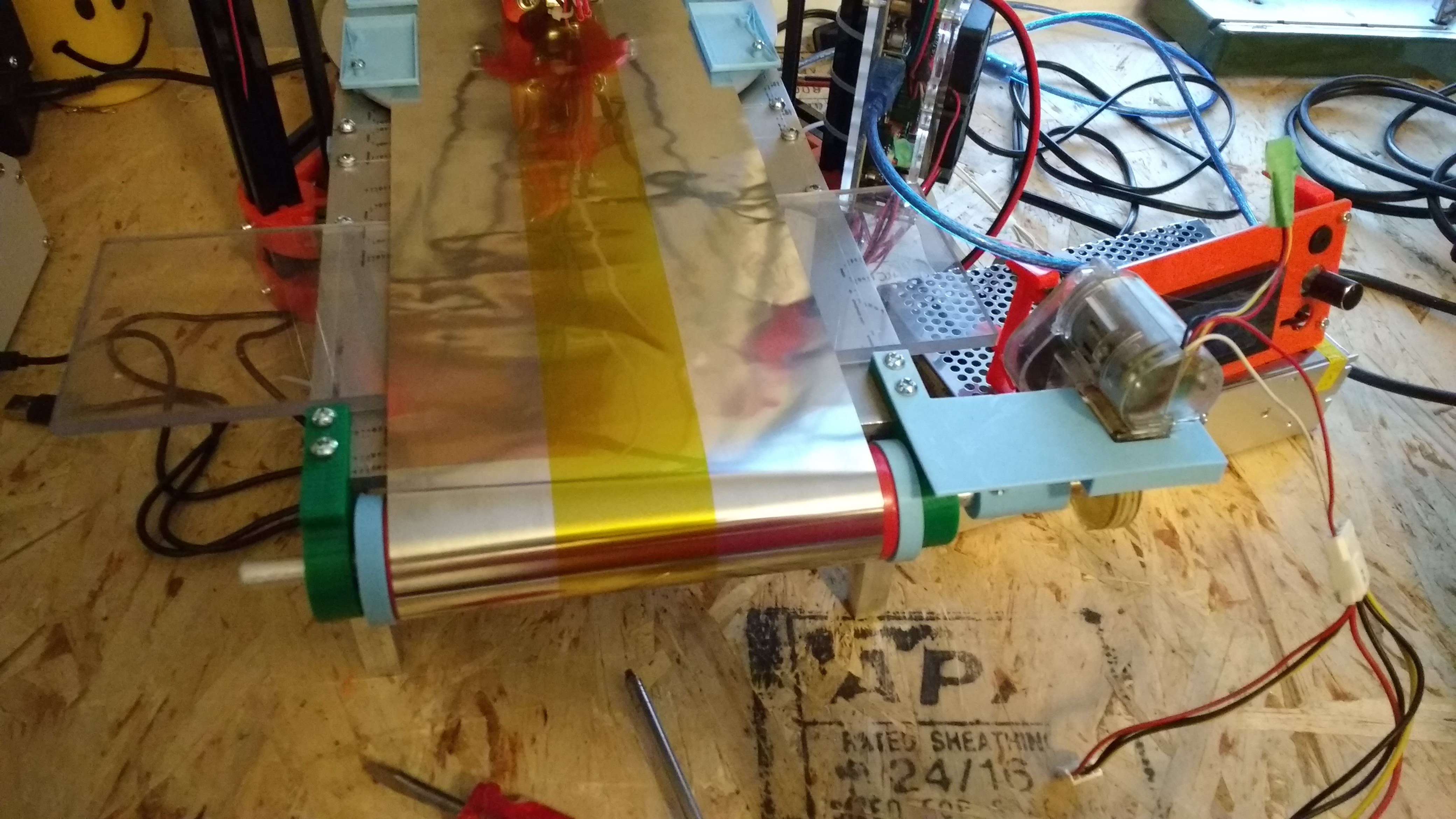
I powered the motor with an upcycled 120V computer power supply. Before adding logic to the circuit, I ran a few tests with the motor.
![]()
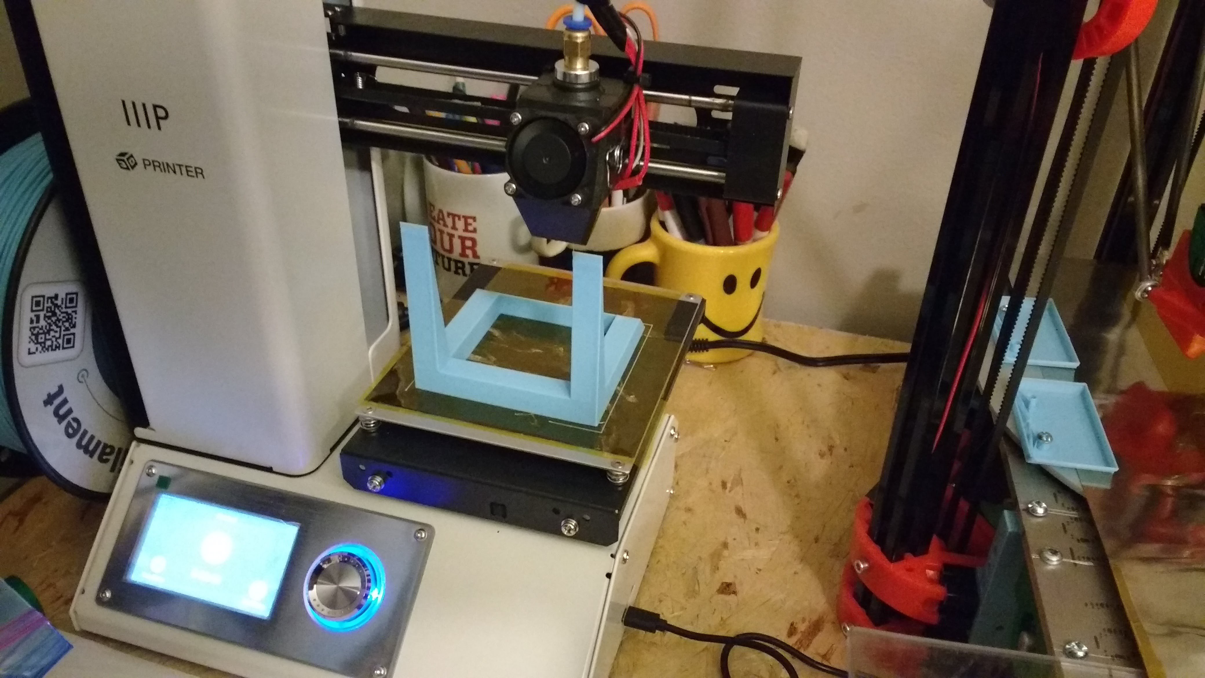
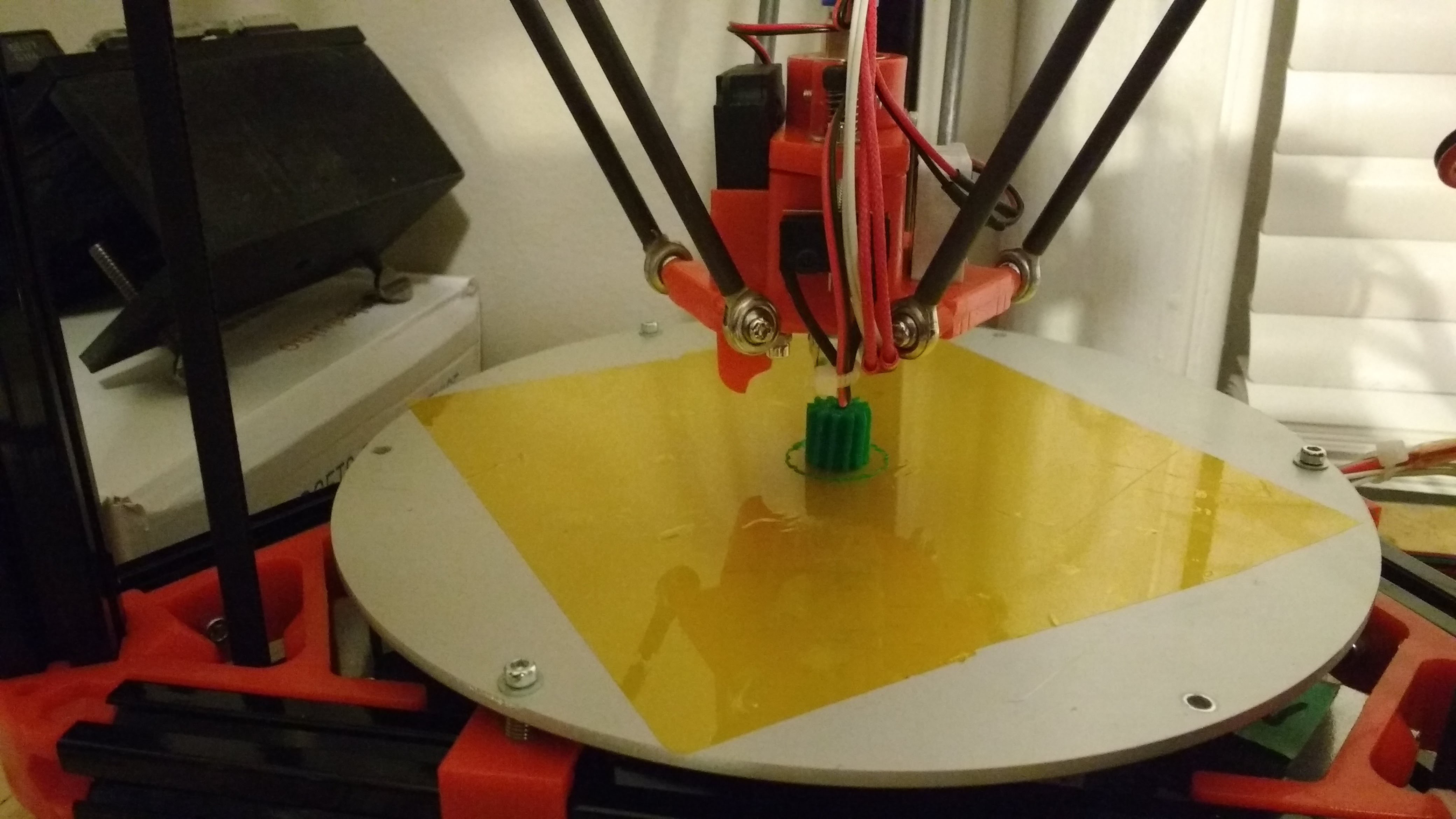
[Figure 6: Testing Printing on Conveyor Belt]
![]()
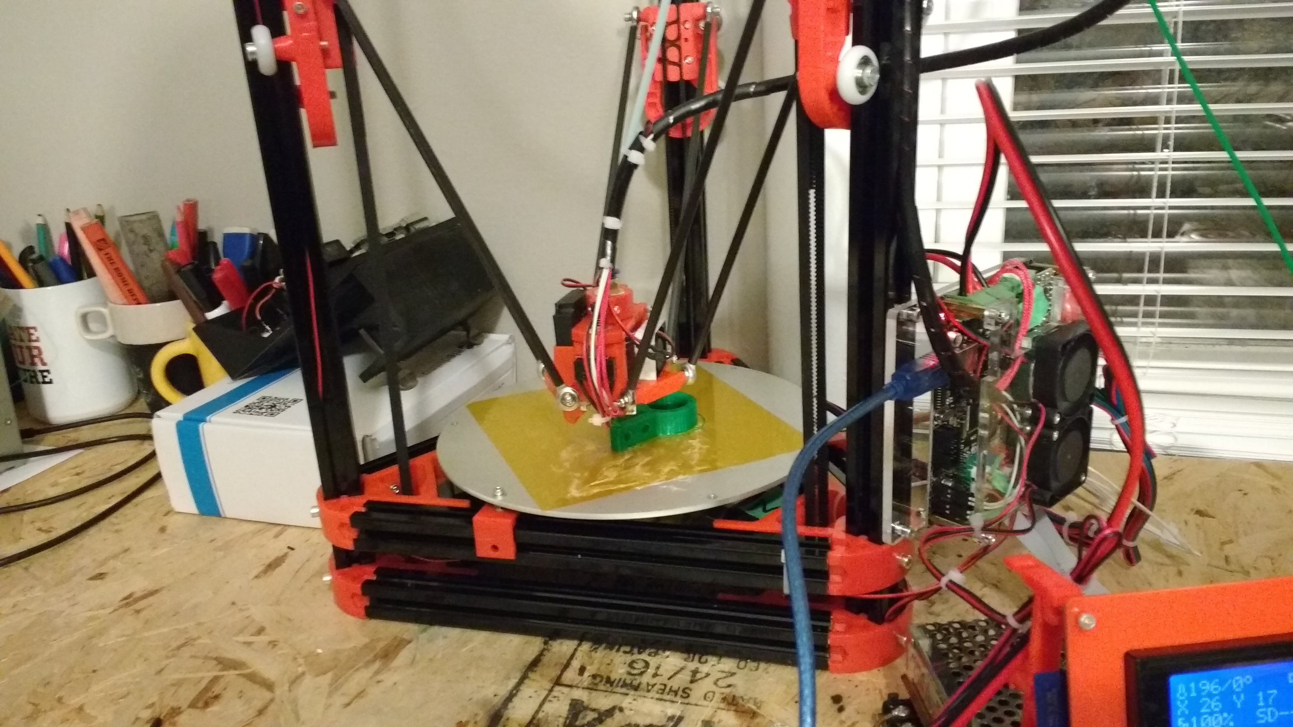
[Figure 7: Testing Ejection System]
It is important to note that the skirt of the print is not ejected by the conveyor in the shown example. After adding the shear, the skirt is also removed consistently.
-
Dry Testing the Conveyor Belt
04/07/2018 at 03:42 • 0 commentsI recalibrated the 3D printer to match the height of the conveyor belt.
I then printed a few parts on the conveyor belt and manually rotated the belt forwards. The parts stuck well to the belt during the printing period, but they would not peel off while I tried to eject.
I have added a stationary shear to help the parts people off. With the stationary shear, the parts peel off perfectly.
![]()
[Figure 1: Stationary Shear Tool]
![]()
[Figure 2: 3D Printing Stationary Shear]
-
Log 6 Building Conveyor Pt. 2:The Frame
04/05/2018 at 17:58 • 0 commentsI have constructed the general frame of the conveyor belt.
I am using aluminum to keep the system light. Additionally, a metal structure will be significantly more robust than a laser cut wood system.
![]()
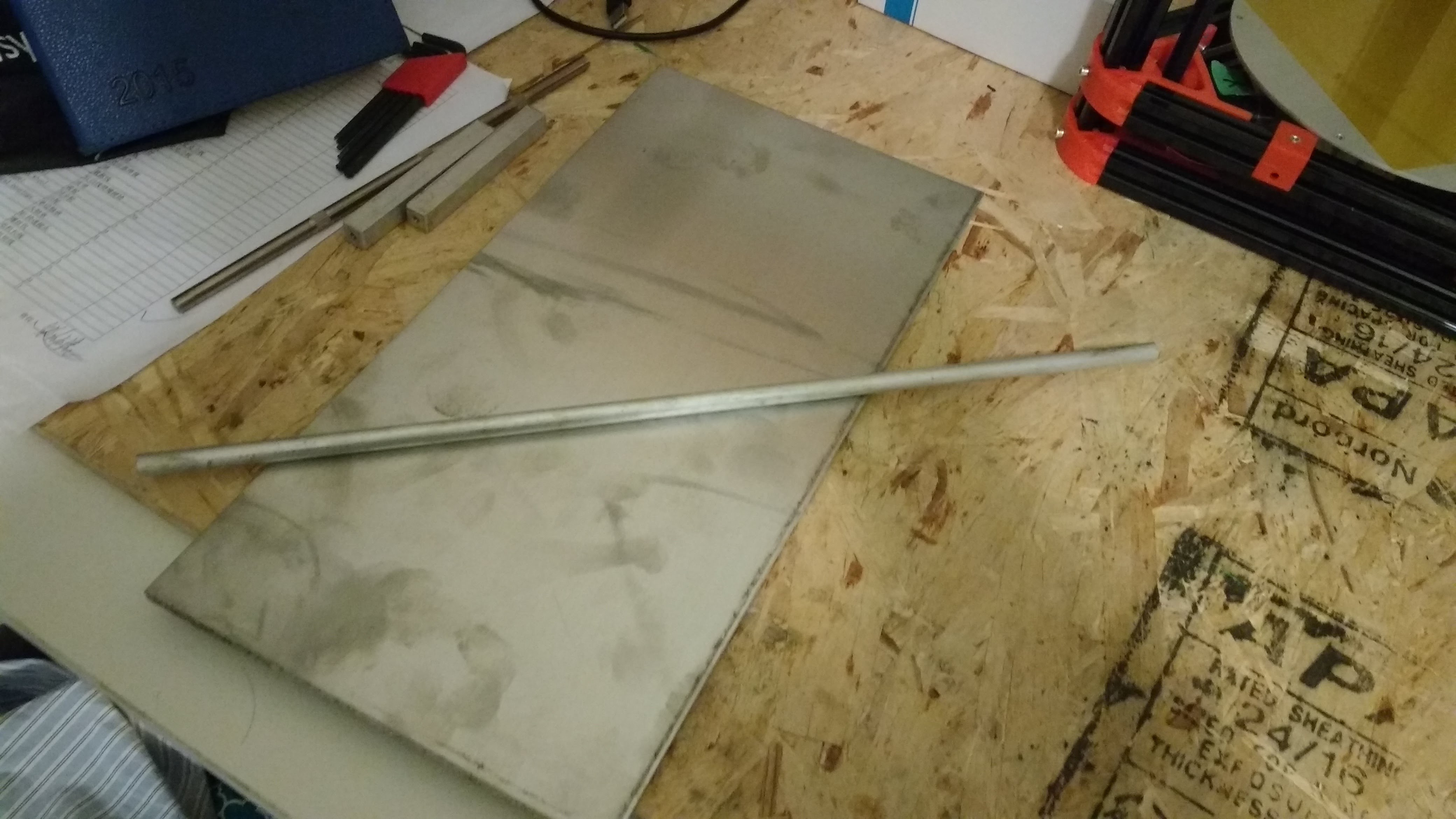
[Figure 1: 6061 Aluminum Plate, Round Stock, and Square Stock]
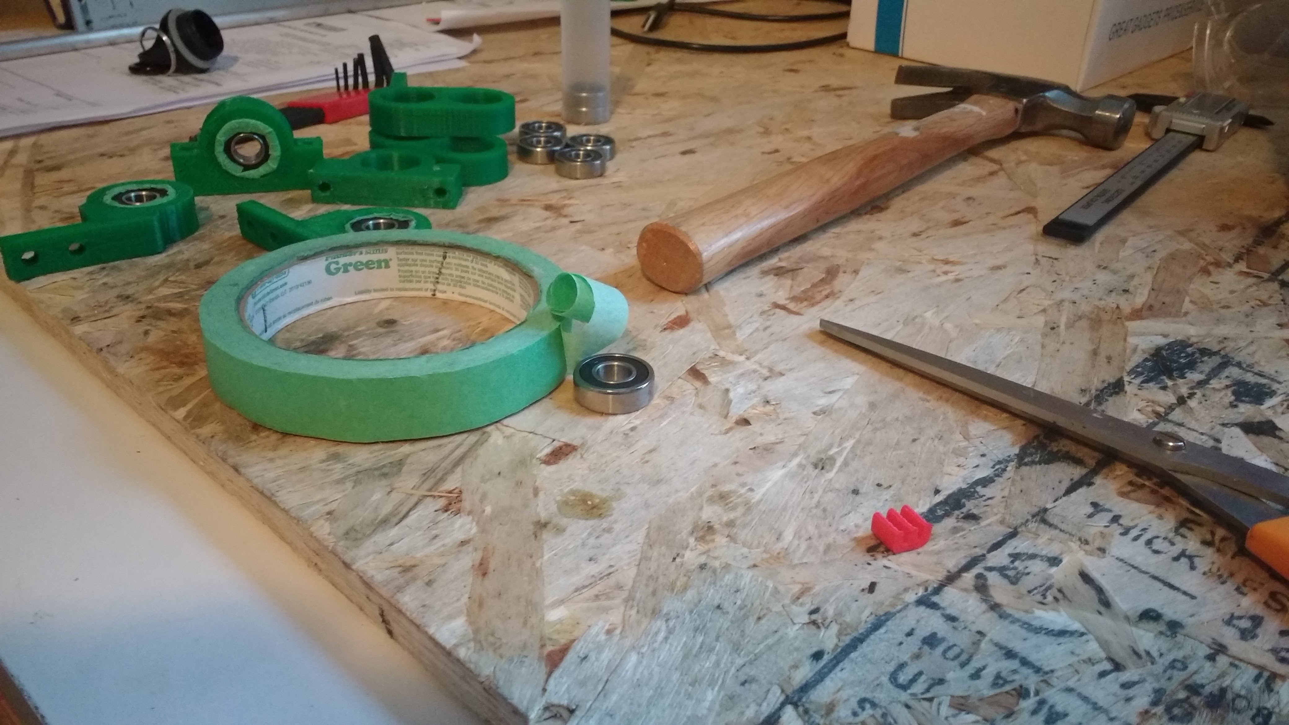
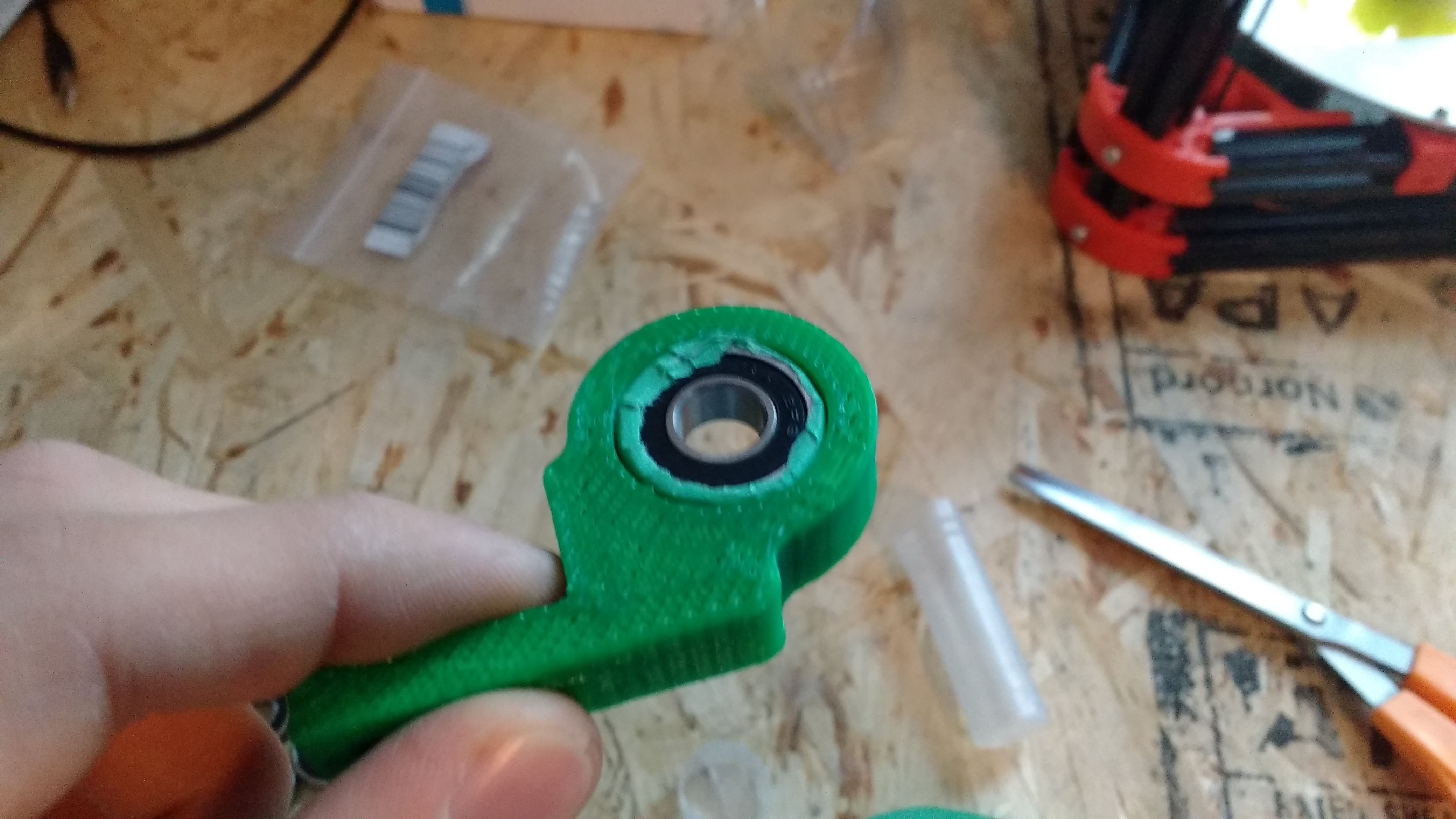
Each of the rollers will be supported by a ball bearings. I have printed bearing housings that mount onto the plate. I thought the bearings would be 0.875 in diameter. This was not the case. Some painter's tape crudely solved the problem.
![]()
[Figure 2: Ball Bearings for Rollers]
![]()
[Figure 3: 3D Printed Bearing Housing]
![]()
[Figure 4: Finding out Ball Bearing isn't 7/8]
![]()
[Figure 5: Increasing OD of Ball Bearing]
![]()
[Figure 6: Inserting Ball Bearing into Housing]
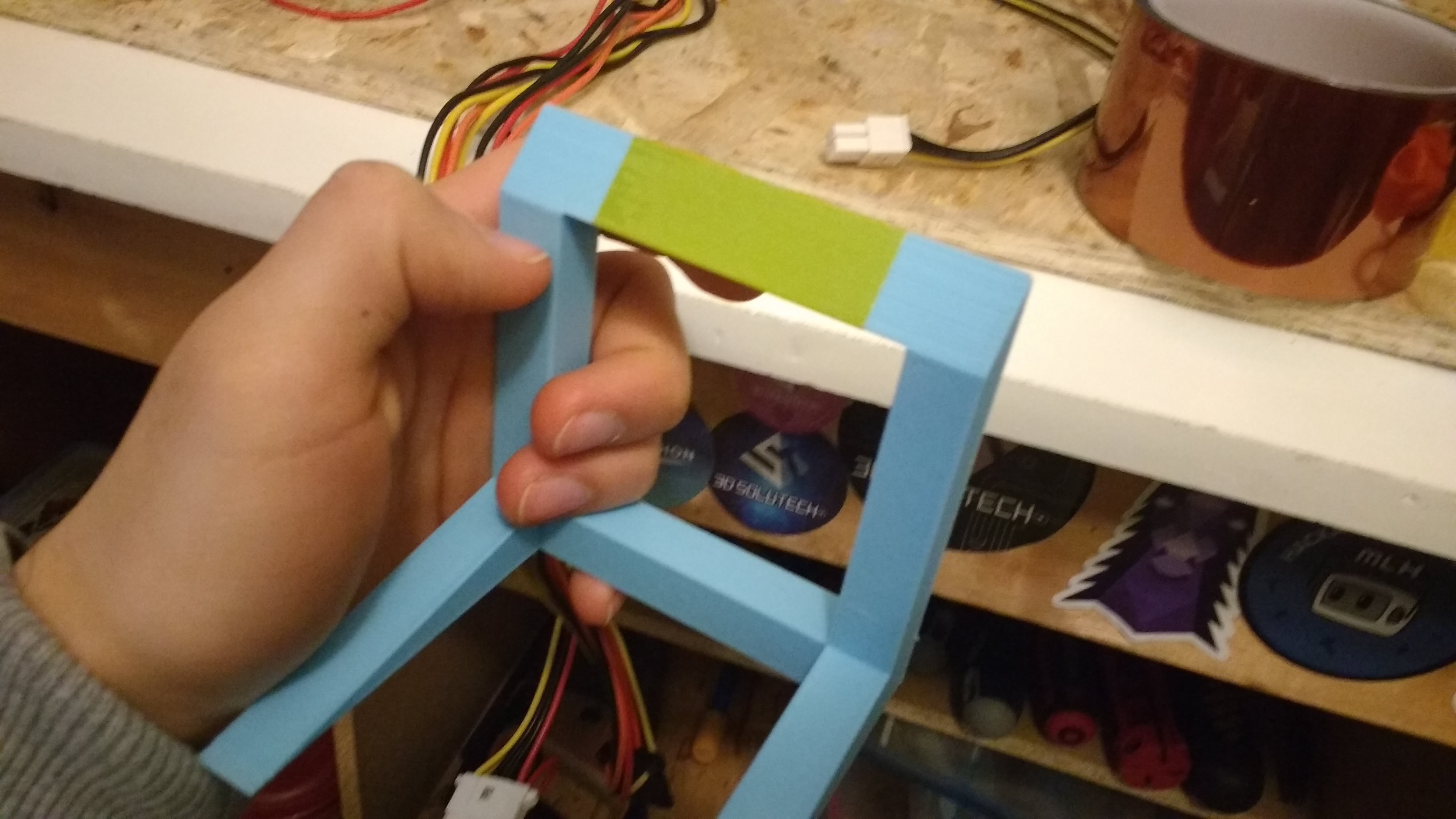
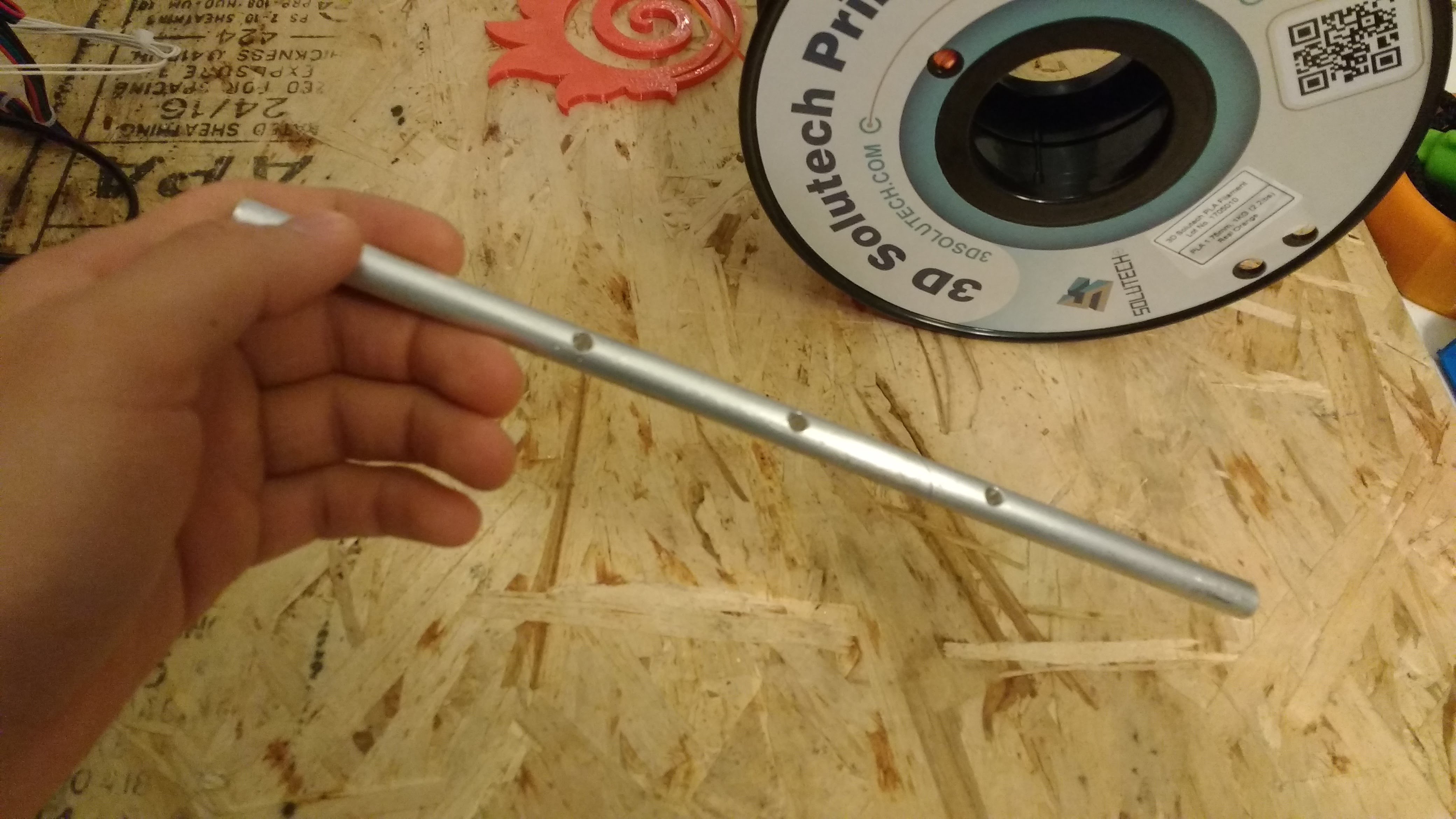
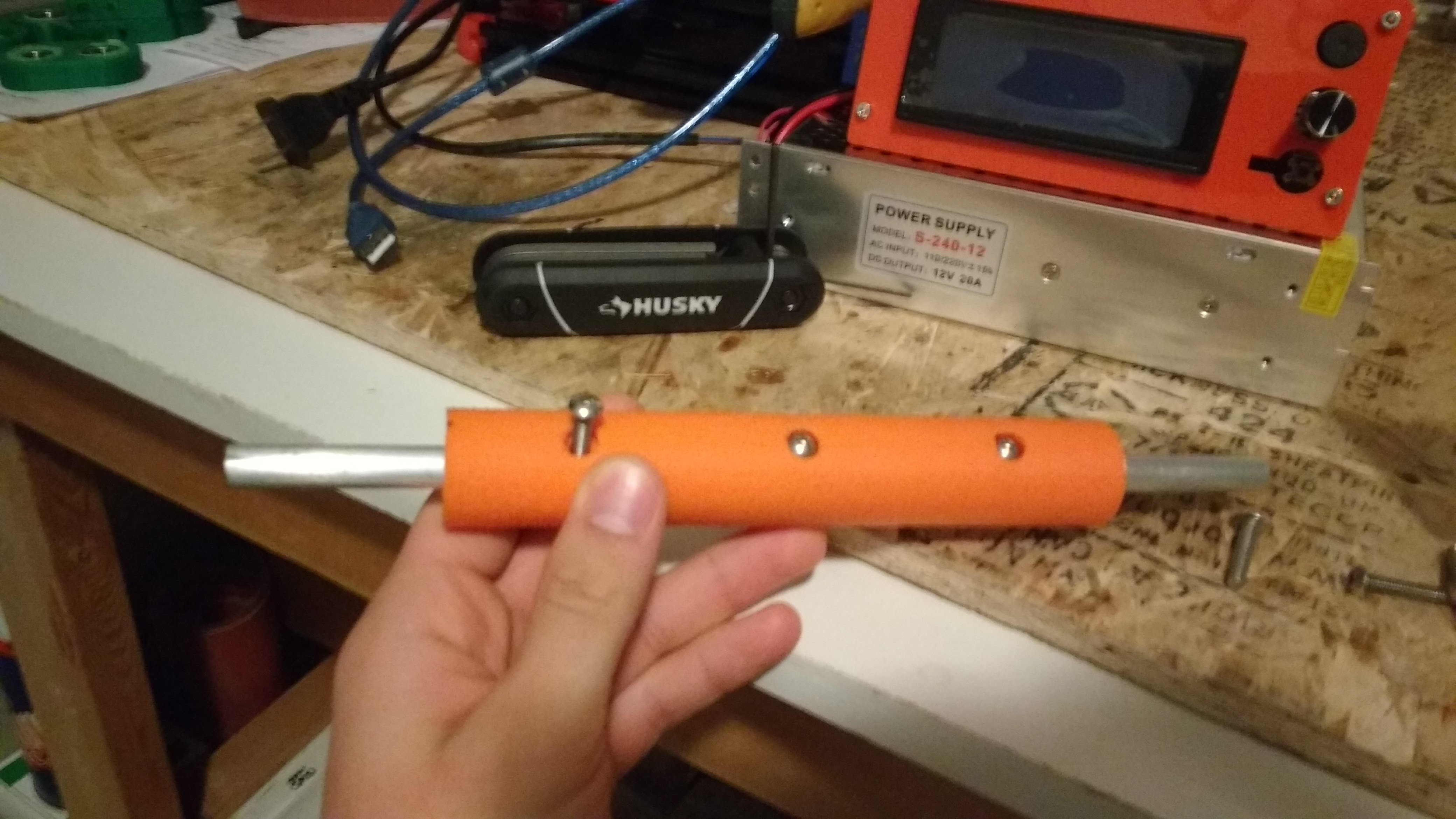
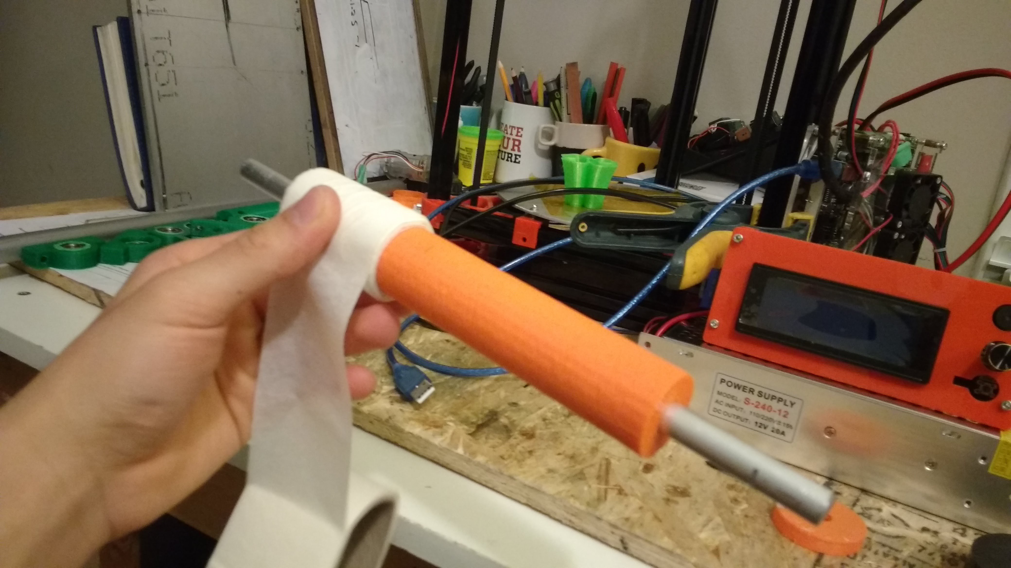
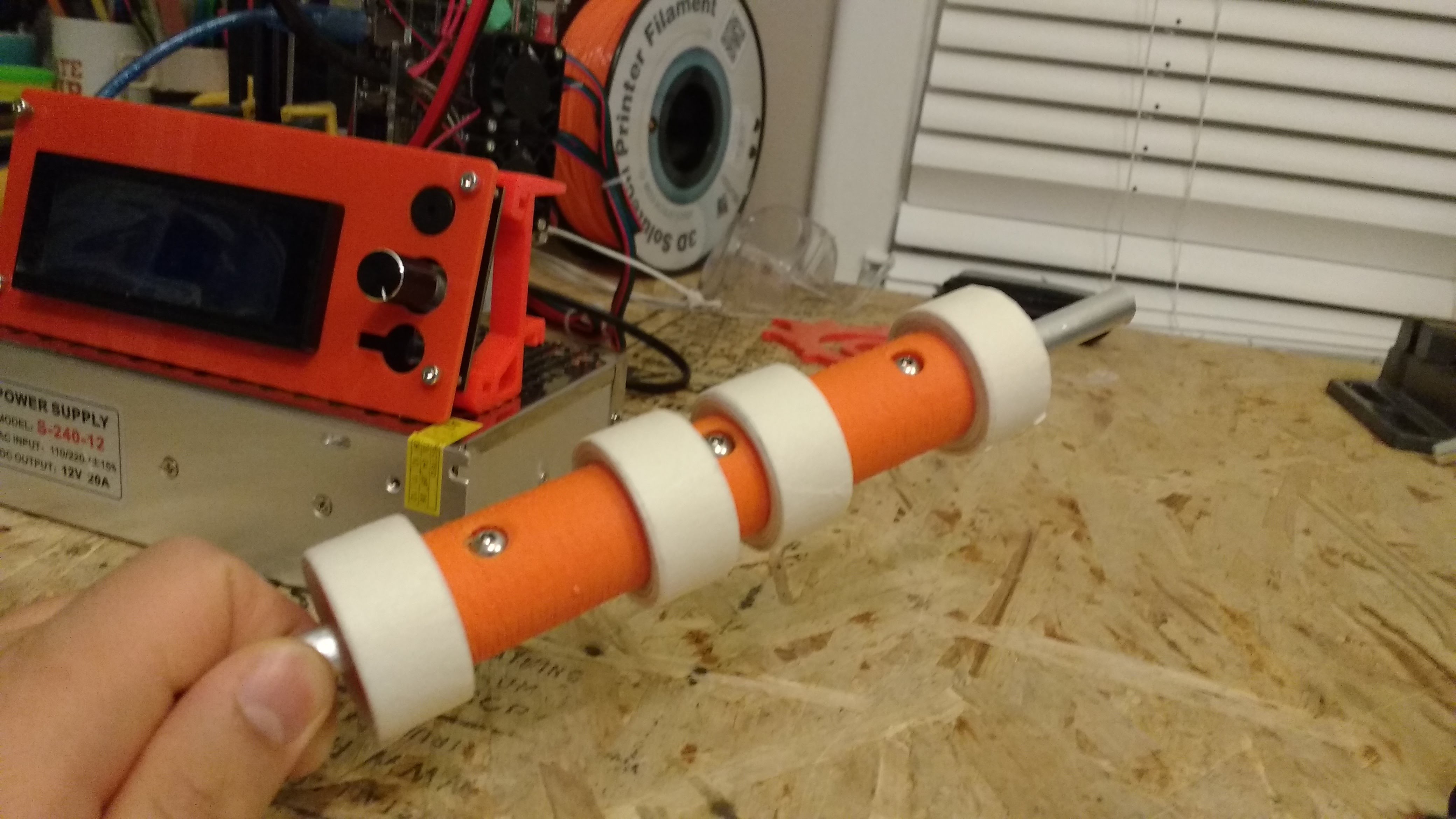
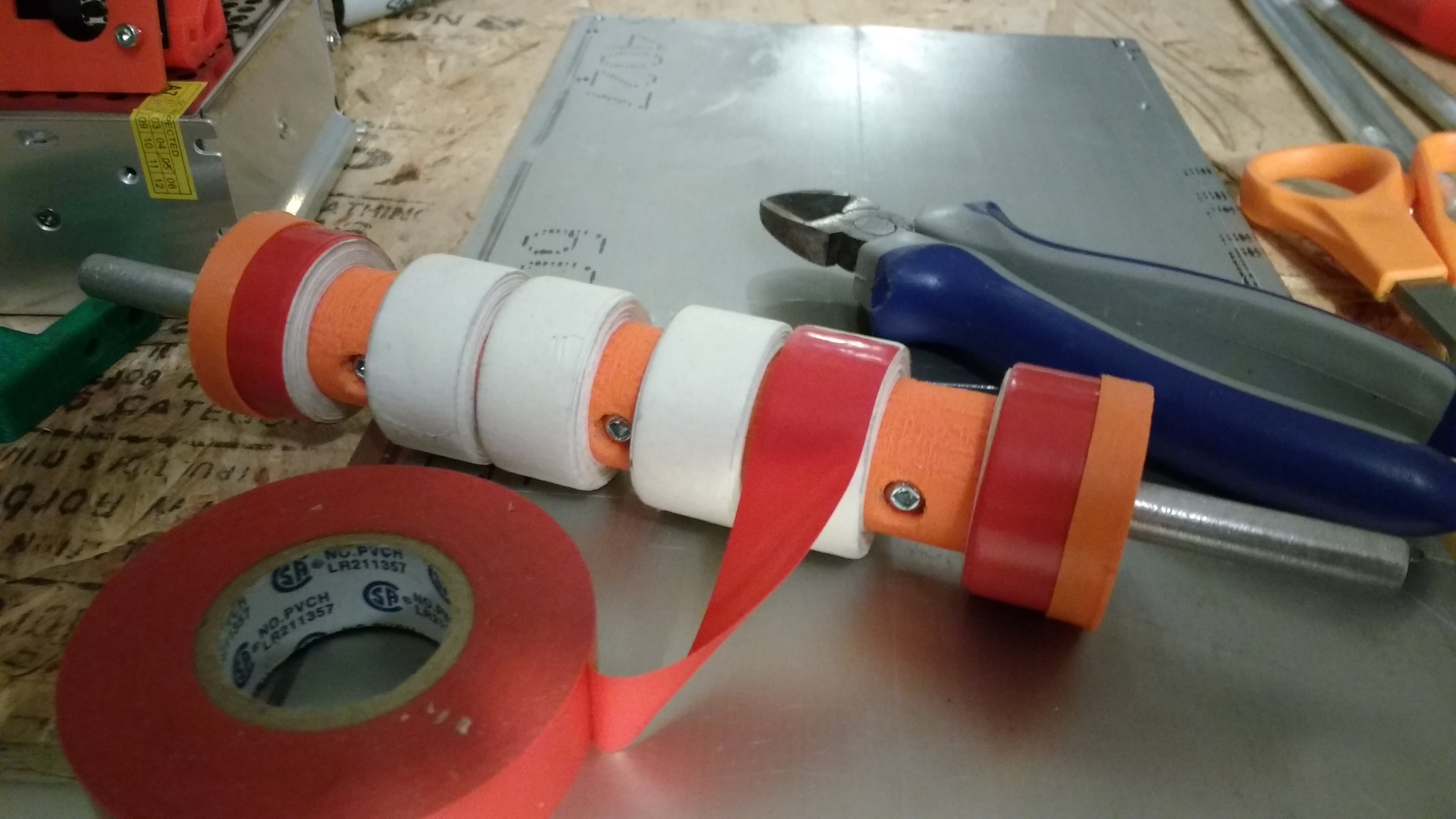
The idle rollers are simple 3/8 rods. To increase traction, the motorize roller is wrapped with high friction material. Additionally, a 3D Printed adapter increases the diameter of the roller and resultingly the contact area with the belt. Originally, the roller was wrapped with a rubber mat but this material was replaced with electrical tape. The metal has tapped holes for the bearing housings.
![]()
[Figure 7: Adding Mounting Holes to Axle for 3D Printed Adapter]
![]()
[Figure 8: Mounting 3D Printed Adapter]
![]()
[Figure 9: Increase OD with Masking Tape]
![]()
[Figure 10: Roller Wrapped with Masking Tape]
![]()
[Figure 11: Wrapping roller with Electrical Tape]
![]()
![]()
[Figure 12, 13: Rollers Mounted on Plate]
The heating bed was mounted to the metal plate. Clearance holes were cut for the heating bed cables. Plastic spacers were placed beneath the heating bed to ensure the entire bed does not turn into a heat sink.
![]()
[Figure 14: Adding Clearance Holes to Plate for Heat Bed]
![]()
[Figure 15: Mounting Heating Bed to Plate]
I built the belt, last since I knew it would be the most irksome component. I make the belt by connecting two ends of a steel shim with Kapton tape. Since the shim has a small thickness of 1 thou., it conforms nicely to the shape of the rollers. I tensioned the belt by lowering the middle roller with spacers. I wrapped the belt with Painter's Tape to provide a nice printing surface for the print head. I printed simple mounts to connect the Delta 3D printer to the print bed and machined metal stands for the front of the conveyor.
![]()
[Figure 16: Connecting Shim with Kapton Tape]
![]()
[Figure 17: Apply Painter's Tape to Belt]
![]()
[Figure 18: 3D Printed Mounts for Conveyor Belt]
![]()
[Figure 19: Metal Stand for Conveyor]
I plan on running a dry test before I motorize the front roller. I will print a part on the conveyor belt and then manually rotate the front roller. I will investigate the effectiveness of the belt in ejecting the part.
-
Building Conveyor Belt Pt 1: The Design
04/05/2018 at 07:06 • 0 commentsMy next step is to build the automated conveyor belt.This mechanism will remove finished print jobs by rolling them off. The main inquiry goal at this point is to determine whether a conveyor belt can actually eject 3D printed parts.
I am concerned that the conveyor belt will not apply enough force to separate the 3D printed part.
The conveyor belt will have three rollers each of which are connected to ball bearings. Two of the rollers will be idlers and one will be motorized. The motorized roller will drive the belt with friction. This may cause some slippage issues. The conveyor belt will be tensioned by moving the middle roller.
I will make the conveyor belt out of stainless steel shim stock. The main reason that I am using the material is because it is cheap and easily available.
-
The Starting Point: A Delta 3D Printer
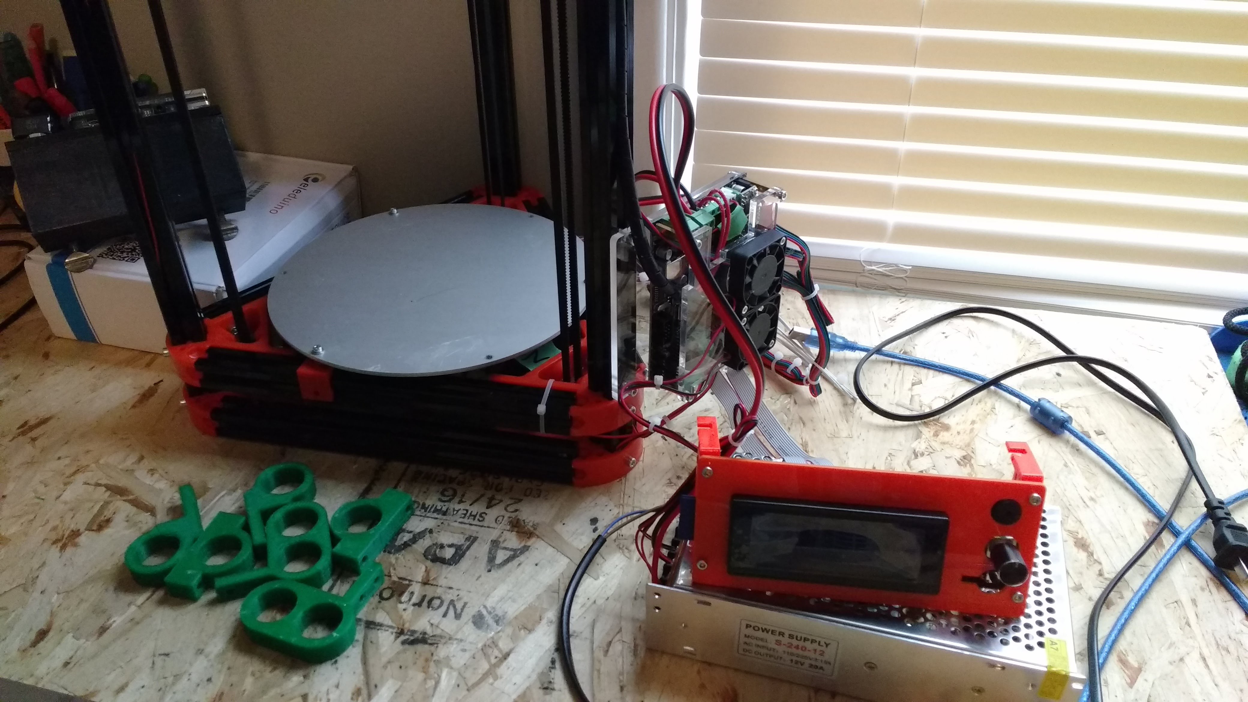
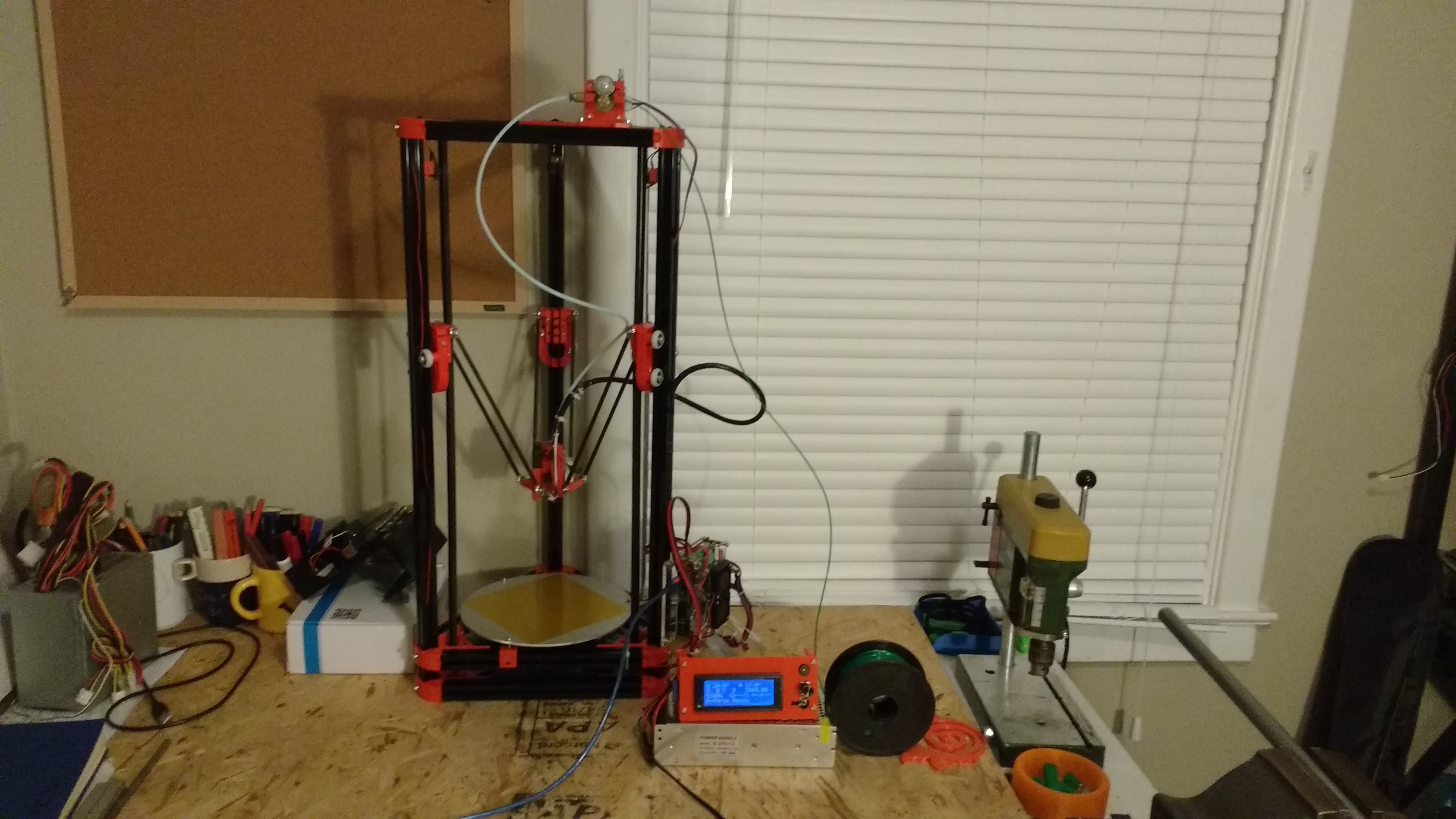
04/05/2018 at 06:57 • 0 commentsI have built a simple Delta 3D printer. The printer has a simple Kossel design. This printer has a large z-axis of 300 mm ensuring adequate room to fit a conveyor belt. I have printed test parts to check whether the print quality decreases after I add the conveyor belt.
![]()
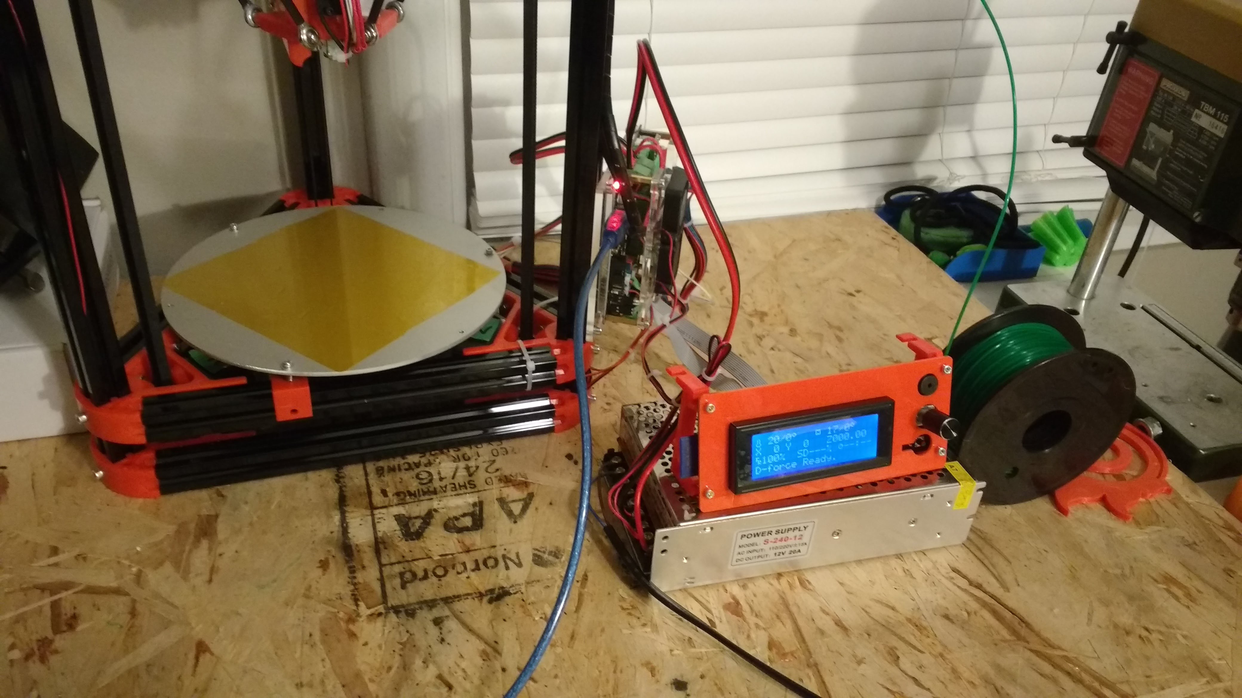
[Figure 1: Delta Kossel 3D Printer]
![]()
[Figure 2: Delta Kossel 3D Printer Closeup]
![]()
[Figure 3: Test Print 1]
![]()
[Figure 3: Test Print 2]
-
WorkHorse 3D Printer Mk 1 Game Plan
04/02/2018 at 07:22 • 0 commentsI am about to begin designing and building the first iteration of the WorkHorse 3D Printer. The purpose of this prototype is to test the effectiveness of the conveyor belt design. I want to see if print jobs easily peel off of a rolling conveyor belt. My current design for the conveyor belt is rather bulky and intrusive. I will focus on simplifying and condensing the design later.
I will add the conveyor belt to a Delta 3D Printer. Delta 3D Printers have a fixed print bed. Because the print bed is static, it will be much easier to place the conveyor belt on top of the print bed. I do no have to worry about the conveyor belt being light enough to move with the bed.
-
Potential Solutions for Automatically Removing Print Jobs
04/02/2018 at 07:17 • 0 commentsThere are multiple actuators that could be used to autonomously eject print jobs. I have researched different methods, all of which have their own pros and cons. I hope to give a brief synopsis of each design below.
Eject Part with Shear
3D print jobs can be ejected with a mechanical shear. A thin wedge can be gradually moved beneath the 3D printed object to remove the part from the print bed. A motorized shear is a relatively simple module to design and build. However, the shear is unlikely to work on large print jobs. The more contact area between the print job and print bed, the more force will need to be applied by the shear to separate the two. Therefore, print jobs with large footprints will be difficult to remove with a shear.
Some 3D printers already employ a pushing method to eject 3D printed parts. It is a common technique to push the print head of a 3D printer against a printed part. This method works for printed parts that have low contact area with the print bed, such as a thin bracelet.
[Figure 1: Ultimaker Ejecting Bracelet]
With this method, users should be concerned by the amount of force being applied by the sensitive stepper motors. Additionally, the movement is likely to defect the calibration in that axis of the printer.
Eject Part by Compressing Plate
Many 3D printing companies are moving towards spring plate beds. To remove parts, users flex the bed to remove the print job. This motion can be automated with a robotic manipulator. The design of the manipulator would be significantly more complex than the robotic shear. Additionally, constant bending of the metal would gradually distort the shape of the bed.
[Figure 2: Spring Plate Part Removal]
Remove entire Build Plate
Many 3D printing factories automate part ejection with removable build plates. In this technique, a removable build plate is attached to every 3D printer. The build plate is generally held in place with magnets. After a 3D printer is finish printing a part, a robotic arm removes the entire build plate from the printer. The robotic arm then places an empty build plate in the printer and the 3D printer prints its next job. Workers are required to actually separate the printed part from the printer. While this solution does improve the efficiency of a fleet of 3D printers, it does not fully automate part ejection. Additionally, the print capacity of the 3D printers is limited by the number of empty build plates available. Furthermore, the machinery required to implement this solution is extremely expensive and requires a large footprint to operate in.
[Figure 3: Print Bed Removal with Robotic Arm]
Eject Part with Conveyor Belt
Instead of 3D printers printing parts on a static plate, parts can be printed on a conveyor belt. After a print job is completed, the conveyor belt can roll off the part and the 3D printer can start printing the next job. This solution allows a printer to print an infinite stream of parts. Additionally, the conveyor belt system can be compact and easily integrated into any 3D printer design. A conveyor belt mechanism is not overly complex.
The WorkHorse 3D Printer will use a conveyor belt system to automatically eject print jobs.
-
The Need to Automatize 3D Printers
04/02/2018 at 07:10 • 0 commentsThe Problem
Even though 3D printing is a newly emerging technology, it has rapidly became mainstream in education, manufacturing and many other industries. 3D printers allow anyone to easily produce complex parts.
However, these machines have one critical flaw. After a 3D printer has finished printing a part, a person must physically go to the printer and remove the part from the print bed. A 3D printer cannot start its next print job until the previous part is removed. This constraint cripples the productivity of 3D printers. If 3D printers could automatically eject their prints, then they could print out a constant stream of parts. The efficiency of the machine would drastically increase.
Many businesses already use 3D printers to manufacture product. Currently, their manufacturing capabilities are constrained by the constant need to manually remove/start print jobs If this task was automated, it would be easier for more companies to use 3D printing for volume manufacturing.
Personally, I work in a 3D printing lab that prints hundreds of parts for my fellow university students. From my position, it is obvious that this constraint significantly limits the number of print jobs our lab can complete per day.
[Figure 1: Problem Pitch Video]
The Solution
The purpose of this project is to build a fully automated 3D Printer: The WorkHorse 3D Printer. The WorkHorse 3D Printer will have some sort of manipulator that autonomously ejects finished print jobs from the printer. With this novel feature, the WorkHorse 3D Printer will be able to print a constant stream of print jobs without human intervention. This will be a breakthrough for the 3D printing industry. Automatic part ejection will improve the functionality and capability of 3D printers. Within the next few years, autonomous part ejectors will be as ubiquitous to 3D printers as paper ejectors are to paper printers.
Key Objectives
Robust
This machine is intended for mass production purpose. Ideally, the machine would run 24/7 outputting a constant stream of print jobs. Of course, scheduled breaks would have to be programmed into operation to prevent overheating. But the machine should reflect its name. The WorkHorse 3D Printer should be able to print a wide variety of parts, for long periods of time, without breaking down.
Modular Design
There were over 250 000 3D printers sold last year[1]. There are multiple common 3D printer designs each with their own pros and cons. Every 3D printer would benefit from an automatic part ejector. Ideally this project would produce an automatic part ejector that could be easily integrated into a variety of 3D printer designs. The automatic part ejector used in the WorkHorse 3D printer should be modular so that it is easy for other 3D printers to incorporate the mechanism.
Easy to Use
The WorkHorse 3D Printer should have an intuitive software application that allows users to manage the print job queue.Users should have the ability to edit/delete/add print jobs while the 3D printer is running. Additionally, the WorkHorse 3D printer should be simple to maintain and recalibrate.
References
[1]Wohlers Associates. (2017). Wohlers Report 2017. Fort Collins, CO. [Electronic]. Available: https://wohlersassociates.com
Automatic Infinite 3D Printer
The Automatic Infinite 3D Printer (i3D) gives anyone the power of a factory.