Close
0%
0%

Locomatrix - 3D POV - a different approach

Let's use some rotary to linear movements to display things in 3D. I have no idea if this will work, but hey, I'm gonna try it anyways...

Similar projects worth following
This is an attempt to make a 3D POV Display by moving an 8x8 LED Matrix on the z axis. This could be upgraded with bigger matrices and more colors. I'm also thinking about making a real steam-punk version - steam powered and with bulbs.

Timeline:
01.06.14 3D printed parts ordered
06.-08.06.14 Working out the electronics
09.06.14 new motor and gears ordered
12.06.14 probably arrival of parts

The plan is to build a persistence-of-vision display, where a small Matrix of 8x8 LEDs will be moved around by a motor on one axis. Starting small I will take a 32mm x 32mm LED matrix. I have to figure out a rough box where the movement is exploitable and get some fancy software hacked together. I'm thinking about 4 rods, where the led board can slide on, with a copper pipe soldered to the boards for alignment. There will be a lot of forces going on and I will have to deal with electrostatics and heating problems on the moving parts, I guess. 

Syncing the display to the movement will be another thing to solve, but seems manageable for an arduino.  

So if it will work, I'm going to upgrade it to a 8x8x8 6cm rgb matrix, but for now let's start small...

  • learning to youtube

    davedarko03/02/2015 at 10:25 5 comments

    So I fought with blender for the last 3 or 4 days to get this video rendered and cut 50% out. I made a fatal mistake and recorded the whole thing in 50fps and had to find a way to recode it to 25fps - sad that I will have to use Magic Lantern just for the option to record 1280x720 at 25fps, but I will try it. This is unscripted and you can clearly hear me thinking :D There is a jump mark to get to the part where it's moving. Sounds like an old film projector, so I still hope I can get something 3D out of it.

  • Revision 2 - 3D printed parts

    davedarko02/27/2015 at 18:27 2 comments

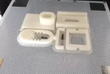
    I want to have some clean, new and updated prints - so I had to basically redesign everything, except the gear parts. The gear that is stuck on the motor is bought and still on there. The motor will be fixed with screws and the standard screw size is M3 now. It's currently printing in full with 140mil layer height of orange ABS. I will update this log, as soon as the prints are done.

  • Random thoughts on how I should continue

    davedarko01/23/2015 at 23:43 0 comments

    • reprint parts that were not printed on the zortrax and that warped a lot
    • use different / decoupled power supplies for each system
    • add a click counter in software and test without mechanics

  • fixed the gears - still no 3D stuff

    davedarko08/14/2014 at 16:15 0 comments

    see for yourself...

  • random idea

    davedarko06/24/2014 at 11:42 0 comments

    I just thought about turning a rubik cube into an interface or lock by using 6 encoders as a way to grab the rotation and send those inputs to an rgb 3x3x3 cube or 8x8x8 rgb locomatrix, when ready ;) I'm still sidetracked by my continuum quantum device prop build, repairing and upgrading my printrbot simple and work of course but always try to come up how to integrate functions and interfaces into props and things laying around. 

    Googe found me this:

    http://www.fastcodesign.com/1671039/a-music-making-interface-that-riffs-on-the-rubik-s-cube

    Ha, and this, so I'm not the first - good!

    http://www.3ders.org/articles/20131206-transform-an-entire-building-into-a-playable-rubik-cube.html

    http://interactive.javierlloret.com/puzzlefacade/

  • The Hackaday Price

    davedarko06/19/2014 at 21:50 0 comments

    The community voting today alarmed me to finally put in a contest entry to have at least a glance at winning something. This doesn't feel like the best choice for the contest to win it, but I could not come up with something really good "connected thing" and didn't want to start a new project so I felt the best would be to pick an existing. Let me go through the pros and cons of my projects.

    Read more »

  • Yet another frustrating adventure

    davedarko06/15/2014 at 13:22 0 comments

    Yesterday i spent 5hours fixing my printrbot simple so I could go on my self with the gearbox and the new motor. I got almost the same motor speed as before with no smoking motors. But this time I blew off a capacitor on an arduino by not giving attention to the poles. Gladly I was able to rip it off and place a new cap on there. I still have to use a motor bridge or a pwm control.

    Read more »

  • oh dear - i need to research

    davedarko06/08/2014 at 20:43 2 comments

    So the motor was definitely the wrong choice. Or may be not the best for a directly driven gear. I have to come up with a gearbox, speeding down a beefier motor to make it work. The arduino was underfed with power when the motor turned so there was no way to get a satisfying light show :( I'm going to replace the arduino with an attiny45 later, but it was easier to get started with this setup. For the time it moved, there was almost no friction on the 3D printed parts. Any Ideas?

    Here is a video of it not moving but glowing, a sonic screwdriver and me saying "crap".

  • first motion test (no leds)

    davedarko06/06/2014 at 22:18 6 comments

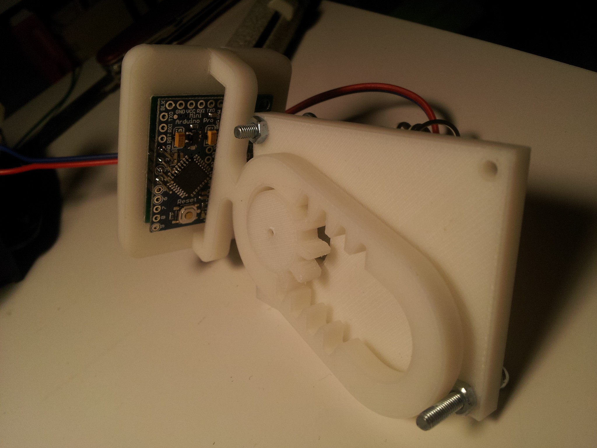
    I could not resist to put the printed parts together! This is my test rig, I intend to build a fancy looking one but not for now.

  • my boss is awesome

    davedarko06/02/2014 at 07:50 0 comments

    and this is why, already on the way:

View all 14 project logs

Enjoy this project?

Share

Discussions

MRMAINT62 wrote 10/05/2018 at 02:00 point

One way to separate your POV display from the electronics and prevent them from being shaken to pieces is to have the moving display surface be a screen that displays a projected image onto the moving screen. Maybe use a mirror surface and mount it 45 degrees to a display screen that has a video playing that is synced to the motion of the mirror. The viewer would be looking 90 degrees to the video display (45 degrees to the moving mirror). The video would give continuous display synced to smooth continuous motion. 

If you want to use an LED display that actually moves back and forth, you could eliminate the wires by having separate controllers for the moving screen and the stationary motor and sync them using WYFI transmission. If you want to eliminate a battery on the moving display then add a coil that passes by a stationary battery and generate the screen system power from the movement. The signal generated by the coil passing the magnet could also generate your pulse for establishing position for the image sync.

  Are you sure? yes | no

Roman M wrote 03/03/2016 at 21:54 point

See amazing LED project here: http://kck.st/1Oi2sHC
Simply and affordable...

  Are you sure? yes | no

PointyOintment wrote 03/04/2016 at 06:59 point

Not 3D

  Are you sure? yes | no

Bira wrote 03/11/2015 at 10:21 point

Cool idea! I hope to see it working. Did you consider using a linear motor instead of converting rotation to linear motion? I was thinking about fixing somehow the LED matrix to the cone of a subwoofer, feeding in some suitable waveform and seeing the result. 

  Are you sure? yes | no

davedarko wrote 03/11/2015 at 10:41 point

First of all, thanks :) A linear motor sounds a bit too exotic to obtain for an average hacker and this projects focus is on getting something easily repeatable out of it. There were many good advises like "use a solenoid" and "get rid of the DC motor and change for a stepper motor" - valid points and probably a good step for improving the design. But I also like the idea of keeping it simple to motivate others to build and may be even to improve it oneself. I like your subwoofer idea :) Feel free to post a link here, If you decide to make a project!

  Are you sure? yes | no

frankstripod wrote 03/11/2015 at 11:30 point

I am on board with your "easily repeatable" method, and like that you are focused on the inspiration from the old video. I love the subwoofer idea as a
separate project. Nice use of acetone, did it get smooth enough to
eliminate your fear of not using lubricant?

  Are you sure? yes | no

Bira wrote 03/11/2015 at 12:50 point

That why I thought of the subwoofer. It's not expensive (some of them, at least), easy to find, and many 5.1 or 2.1 computer speaker systems come already with an amplifier. You can think of a subwoofer as a linear motor attached to a cone. If it has enough excursion, it could be a way to simplify the project since you would have a linear motor and driver electronics in a single, of-the-shelf (and hopefully cheap) package. As a plus, you might be able to use the sound input to the amplifier to synchronize the display.

  Are you sure? yes | no

davedarko wrote 03/11/2015 at 13:24 point

@Bira - sounds indeed like a good plan!

@Frankstripod - i'm quite confident to get some good movements out of it for at least a while. It's just too loud and annoying to test it for a long time ;)

  Are you sure? yes | no

Eric Hertz wrote 03/11/2015 at 20:16 point

I used a couple subwoofers with mirrors on 'em, once, as an X/Y system for a laser-pointer... Was able to draw (rounded) triangles, but a four-leaf-clover was too much for the momentum of the setup. A better amplifier and possibly some intentional overshoot in the audio-signal at the corners, and *certainly* lower frequencies and lighter/better-affixed mirrors would've done the trick. Anyways, I'm saying, the subwoofer-linear-actuator's a great idea for something like this, and especially if you're driving it at a fixed/known-functional frequency. Props.

  Are you sure? yes | no

Eric Hertz wrote 01/31/2015 at 04:30 point

Props on the Hacklet mention!

Cool idea, I've never seen anything like it.

I think the video or maybe a photograph would show its 3D-ness if the display was tilted slightly away from the camera. And I dig how you're thinking "Steam-punk" seeing as how it's similar to a steam-engine. Cool.

  Are you sure? yes | no

davedarko wrote 01/31/2015 at 10:22 point

Woohoo :) I should work on this again immediately, now that it got some attention. At one point I got frustrated enough to put it in a box and do lots of other things. I need a good rig to hold this little monster and have to redesign and update some parts.

  Are you sure? yes | no

Eric Hertz wrote 01/31/2015 at 11:01 point

"At one point I got frustrated enough to put it in a box and do lots of other things."

Do I know that feeling :)

  Are you sure? yes | no

Griff wrote 08/13/2014 at 18:52 point
I have seen quite a few POV projects and really like the idea of making a 3D version. I think this will look absolutely amazing once it is running.

  Are you sure? yes | no

davedarko wrote 08/13/2014 at 19:26 point
thx, I guess I have to take another look at it :)

  Are you sure? yes | no

Alana B wrote 08/12/2014 at 22:19 point
Very curious if this will work! I wanted to do something similar but spinning the display. Good luck!

  Are you sure? yes | no

davedarko wrote 08/13/2014 at 06:02 point
Thanks for your interest :) I have to find some motivation again, since it's always been a big learning / failing event. about your idea, there is this multi blade spinning thing on here, where basically many rotating povs are stacked - these allow one to see it from every angle while iI'm not sure a rotating matrix would not only give you the half of a cylinder?

  Are you sure? yes | no

davedarko wrote 08/13/2014 at 07:47 point
indeed mr. pointyointment. This blade setup is really clever!

  Are you sure? yes | no

Bruce Land wrote 07/28/2014 at 17:16 point
I think that you are using the right technology for this. LCD is hard to update fast enough. LEDs are very fast and tough. I wonder if a 3D vector display (as opposed to raster) would be efficient.

  Are you sure? yes | no

davedarko wrote 07/28/2014 at 20:08 point
I only heard of CRT vector displays, would be a nice touch to have something like a light sculpt looking like a 3D print though.

  Are you sure? yes | no

Bruce Land wrote 07/28/2014 at 16:28 point
I saw a version of this in 1964 using a small CRT being banged back and forth in a plexiglass cylinder by a solenoid, and plotting surfaces computed by an analog computer. The CRT had to be replaced about twice an hour.

  Are you sure? yes | no

davedarko wrote 07/28/2014 at 17:01 point
Sounds really cool :D ideas are never unique I guess...

  Are you sure? yes | no

zakqwy wrote 07/28/2014 at 17:05 point
Hahaha that's amazing! Assuming the HV supply is stationary, I can just imagine wire fatigue on the flyback lead causing it to eventually fail, leading to all sorts of problems. That would have been neat to see.

  Are you sure? yes | no

zakqwy wrote 07/28/2014 at 17:06 point
Dave--to Bruce's point, have you thought about a big solenoid? Might help you deal with wear on the 3D printed bits.

  Are you sure? yes | no

davedarko wrote 07/28/2014 at 20:05 point
I have to admit, I was a bit frustrated since my last attempt, mainly because the printed parts I printed on my printrbot simple weren't as good as the printed parts from the zortrax printer my chef owns. Since then I calibrated a lot and tweaked my preparations for printing (heating the aluminium bed with a heat gun etc. ) and have to revisit the parts, free the new motor from the old prints and start again, with a L293D. I've never used a solenoid before, so this would throw in another unknown to the already weird setup.

  Are you sure? yes | no

Adam Fabio wrote 06/22/2014 at 04:13 point
Dave - this seems like a great idea. I've always been mesmerized by mechanical movements as well. Thanks for entering The Hackaday Prize. If you go with bulbs in your steampunk version, make sure to get bulbs that can handle rough service - you wouldn't want your machine to shake the white hot filaments apart the first time it's run!

  Are you sure? yes | no

davedarko wrote 06/22/2014 at 06:32 point
Thank you guys for the contest :) if I really start a steampunk version it will be out of wood and brass parts, I guess. And more cylindrical. But I am still unsure about the data I could show.

  Are you sure? yes | no

sad_ken wrote 06/19/2014 at 11:05 point
Amazing idea, this is probably the most original POV display i've seen so far. You could bypass the z-axis timing issues by using an optical encoder to tell the arduino where it currently is.

  Are you sure? yes | no

davedarko wrote 06/19/2014 at 11:11 point
Thank you! With the current design I have a linear movement with no acceleration in speed, so I have no timing issues anymore. There is only the switching of direction I have to follow, I may simply use a switch for that. It all started with a loose idea and now I'm running in problems I have to engineer around ;) to keep going I have to recalibrate my printrbot simple to get reliable prints again.

  Are you sure? yes | no

frankstripod wrote 05/19/2014 at 20:38 point
I really did not want to follow this one, but I could not stop staring at it and wondering if it will work. Hack on!

  Are you sure? yes | no

davedarko wrote 05/19/2014 at 21:03 point
I try to follow everything interesting out here. I have made a javascript filter to get rid of the skullgivings and followers of the other projects, so I only see the relevant updates in my list. I'm curious myself since this was just a silly idea in the first place but seems pretty doable. So thanks again for your interest and good luck for your controller project!

  Are you sure? yes | no

zakqwy wrote 05/19/2014 at 12:20 point
Really cool project. Seems like the Z-axis (or whatever you end up calling the moving axis) speed will constantly change, so you'll have to do some basic trig on the update timing to linearize the display response (decent animation of this at http://upload.wikimedia.org/wikipedia/commons/a/a5/ComplexSinInATimeAxe.gif). PTFE linear bearings and precision ground rods, properly aligned, might be pretty useful for preventing binding and so forth. Looking forward to seeing where this goes!

  Are you sure? yes | no

davedarko wrote 05/19/2014 at 12:52 point
Thank you :) It seems that the GIF animation would be my last step; switching the matrix display for a circular POV display (which would be kind of insane looking, i guess and the forces would probably kill it). But the intention the project follows in the first place is to skip the radial displaying in two dimensions. I still have to fluctuate the timings to display 8 planes with a same distance though and probably misunderstood the animation :D Oh dear, i did. So yeah, I have to do that but gonna let my comment stand to give you the credits for inspiring me to think of the POV in the POV step.

  Are you sure? yes | no

zakqwy wrote 05/19/2014 at 12:58 point
No probskies. I think it should be a pretty straightforward calculation, and one that you can probably implement down the road. Think about it this way: if all three dimensions were linear, then the eight 'depth' updates would occur at T = 0, 0.125, 0.25, 0.375, etc (assuming it takes T=1 to go from fully extended to fully retracted). Since the motor spins at a constant rate, displaying a sphere on the display with that update scheme would result in an obolate spheroid. Realistically, since you're only dealing with a few layers of depth, you could probably manually modify the depth update points until a test image looked undistorted.

I might be getting a bit ahead of myself. Seems like step 1 is hardware! One direction you could think about going: ditch the rotary actuation and use a voice coil of some sort. Hmmm..

  Are you sure? yes | no

davedarko wrote 05/19/2014 at 14:58 point
I will probably start with a 1x1,2x2, ... , 8x8 Matrix and measure the time of one period. Then I will divide that corresponding to the timings I will figure out (shouldn't be that hard) so I can go from there and see what kind of resolution I could get and what motor speed will be acceptable.

A voice coil is also a great idea, regarding the friction and noises and all! But I will stick with the rotary actuation for the show and it's just easier for me to start with.

  Are you sure? yes | no

Similar Projects

Does this project spark your interest?

Become a member to follow this project and never miss any updates