Close
0%
0%

Building a Shapeoko 3 from Scratch

Let's find out if I can use my little X-carve to build a bigger and better CNC router.

Similar projects worth following
Potentially an exercise in futility, this project is attempting to produce a CNC router that can match, or exceed the performance of a stock Shapeoko 3. How hard can engineering a CNC machine be anyways? Follow along to see how the project takes shape, and hopefully doesn't fail to miserably.

First and foremost, this is a challenge build. There are much better ways to go about building a DIY CNC router. I contemplated buying a Shapeoko 3, but decided that building my own could prove an interesting opportunity to grow my knowledge and skills.


Project goals:

  1. Meet, or exceed the performance of a stock Shapeoko 3.
  2. Can’t exceed the price of the Shapeoko 3.
  3. ???
  4. Profit.


Important Tools:

  • Old benchtop mill (I think it’s called a Bench Master)
  • X-carve CNC router


To do list:

  • Make a to do list (Nailed it!)
  • Make a BOM
  • Build three linear motion rails similar to the SO3 specs. (Done)
  • Design and mill motor mount and end plates. (Done)
  • Design and build a z-axis. (Done)
  • Build a flat and level table for the machine to mount to. (Done)
  • Assemble the mechanical components. (Done)
  • Wiring (what a nebulous term, but done!)
  • Calibrate and test performance.
  • Create a fusion 360 file for the entire build.
  • Add to the to do list.

Build Vblog playlist.


  • It's Alive!

    Caleb Peters06/20/2016 at 16:03 0 comments

    It moves! There’s still a few things that need to be done before the machine can go through some trials and do its first job, but it moves! It’s been a challenging project at times, but it’s also been truly rewarding.


    This project has been taking quite a lot of time for almost every step, so I’m a bit surprised how fast I was able to get all of the hardware and electronics mounted to the machine. Not to mention all the wiring done.


    I’m extremely proud of what I’ve been able to accomplish, but I couldn’t have done any of this without the Shapeoko community.

  • Z-Axis!

    Caleb Peters06/13/2016 at 18:42 0 comments

    With the z-axis now complete I think I can safely say that this DIY-Oko will be running before the end of June. It’s crazy to think that I started working on this project back in October, but hard work and patience is finally starting to appear to pay off.

    Sadly, I’m a little bit pressed for time, so a detailed assembly isn’t in the cards. However, I did manage to put together a short video talking about the z-axis and how it went together. The video skips the tedious assembly part, but if you’re interested I also have a video on my channel detailing the assembly of my Shapeoko 2 z-axis which is similar in a lot of ways.

  • Y-axis & Gantry Assembly

    Caleb Peters05/23/2016 at 23:12 0 comments

    Well, the machine is finally taking shape! This week I was able to get the y-axis rails and the x-axis gantry mounted and squared up to the table.

    The main difficulties were dealing with a few slots that didn't line up perfectly with the threaded holes at the ends of two of the rails, and squaring the end plates to the rails. The former truly wasn't difficult just a necessity, and the latter wasn't too hard to accomplish with a bit of shimming.

    I'm quite happy with the progress I've been able to make, and I'm thinking I'll have the machine running under its own power by the end of June. Hopefully that's not too ambitious.

  • Making a Flat Table

    Caleb Peters05/16/2016 at 20:10 0 comments

    One of the more important, but less interesting parts of this CNC build is creating a flat and level surface to assemble the machine on. Since the machine is significantly heavier than my Shapeoko 2, the table structure needs to be strong enough to be part of the CNC frame.

    To accomplish this I built the table frame out of 1" x 3" x 1/8" aluminum rectangle tube. The tabletop is 3/4" MDF, and I think the final dimensions are approximately 4' x 3'. I originally planned on using 4 x 4's for the legs, but was unable to get anything satisfactory from my local lumberyard. I settled on using some rather thin angle steel for the legs, but there's a good chance that I may have to change them out for something sturdier in the future, check out the video and you'll see what I mean. However, maybe I can figure out something to sturdy the legs up, but until then the jury's out on whether or not they'll be permanent.

    As far as flatness goes, I think I did fairly well. I purchased a fairly nice level with a milled surface. Using the level I don't see any high or low spots on the table surface, so I think I did okay.

  • Troubleshooting Alignment

    Caleb Peters05/09/2016 at 18:49 0 comments

    I didn't get a lot done this week with the build, but I did get the time to bolt together the main part of the frame for the first time. There were a few spots where certain parts of the machine didn't want to line up exactly right. At first I thought it might just be the floor being slightly unlevel, but after reviewing some video I shot I realized that something wasn't quite right. It's hard to explain, so I highly recommend watching the video below to see exactly what was going on. However, the long and the short of it was when I moved the gantry along the y-axis the two y-axis rails shifted quite a bit, and one of them even would lift up in the air slightly when the gantry was all the way back.


    After investigating I realized that the upper to rail slots on one side of the gantry didn't line up correctly with the threaded holes on the x-axis rail. It would appear that this was a major problem that was causing what I was observing. It's very likely that there is other factors at play here, but until the machine is mounted to a table I really don't think I can work those out yet.

  • Y-axis Motor Plates & More!

    Caleb Peters05/02/2016 at 17:54 0 comments

    Well, I have a couple of things to show off this week, including the y-axis motor mount plates.

    The y-axis motor mount plates milled out just as well as any of the other parts that I have been making for this CNC build. The little X-carve has been doing a good job, and my strategy of avoiding large profile cuts on these various aluminum plates has meant that the milling time is surprisingly short for each part. I don't think that any individual part has taken more than a half hour to mill.
    Like all Shapeokos this machine is going to use GT2 belts on the X and Y axis. I chose to go with the slightly beefier 9 mm variant which I believe is what the Shapeoko 3's are using now as well. 9 mm belts look deceptively bigger than 6 mm belts until you put them right on top of each other. it would be interesting to know just what kind of a performance increase there really is between the two sizes. However, I've a tendency to think that this is about as big of a machine as I would want to use belts to drive, but then again I haven't seen a spec sheet outlining how much weight these belts can actually handle. Although, this is just a gut feeling on my part.
    Unlike the Shapeoko 3 I've planned a slightly more traditional screw driven z-axis design. I'm using some of open builds' "Tr8*8-2p" lead screw, and Anti-Backlash Nut Block to accomplish this. I'm relying heavily on experience I gained from building my own custom z-axis for my X-carve.
    I picked up some inexpensive hall effect sensors from Amazon. I'm hoping these will work out, but there's no real guarantee that they will. If they do, then at least I'll be able to recommend them unlike the ones I use on my X-carve
    Finally, I've chosen to use a Porter-Cable 450 router as my spindle. I've ripped off all the electronics in preparation to set it up with my superPID. I also picked up one of the 1/8" elaire collet for it. Side note, the elaire collet looks really nice! I've also picked up a DWP 611 mount from inventables. I really like how it's built, but I do have some misgivings on whether or not it will allow for enough z-axis reach. If it doesn't, its not really a huge deal. I designed the z-axis to accommodate the Shapeoko 2/X carve spindle mounting plate dimensions, so I got plenty of options available.

  • Testing Accuracy!

    Caleb Peters04/29/2016 at 13:15 0 comments

    I was working on my DIY Shapeoko 3 build today, and thought it might be cool to see if I could test how accurate the V-rail really was. I think the results speak for themselves.

  • Making the x-axis motor mount plate:

    Caleb Peters04/28/2016 at 15:57 0 comments

    Moving ever closer to getting this DIY-Oko 3 slowly completed. Now I can finally see how one of the motor mount plates will roll along on the rails.

    Materials:
    1X 7" x 9.5" 1/4" thick 6061 aluminum plate

    Feeds and Speeds:
    Depth of cut = 0.3mm
    Spindle speed = 13000 RPM
    Feed rate = 160mm/min
    Plunge rate = 100mm/min


    Sadly this is kind of a boring update. However, everything is going smoothly right now, so I can't complain too much. And, some progress is always better than no progress. Milling out the x-axis motor mount plate really wasn't any harder than the y-axis end plates. The only concern I really had with this particular piece was whether or not my spacing for the v-wheels was going to be correct. Which according to the picture below looks like it's just fine.

  • Milling the y-axis end plates:

    Caleb Peters04/28/2016 at 15:51 0 comments


    I have a feeling from now on the project will have slow but steady progress. So with that, let's take a look at the bit of progress I did get accomplished.
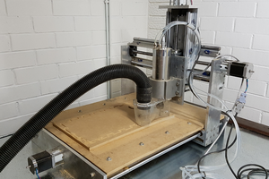
    I've done quite a bit of milling aluminum on my little X-carve, so cutting out a few profiles for the bolts to attach the end plates to the y-axis extrusions and the table frame really isn't anything groundbreaking.


    Materials:
    2X 3" x 8" 1/4" thick 6061 aluminum plate
    2X 5" x 8" 1/4" thick 6061 aluminum plate

    Feeds and Speeds:
    Depth of cut = 0.3mm
    Spindle speed = 13000 RPM
    Feed rate = 160mm/min
    Plunge rate = 100mm/min

    Build process:
    The build process was very straightforward. This is due in part to the fact that I used material that was already at the desired final dimensions. Essentially, all I had to do was mill eight small profile operations for the 1/4" screws to attach the plates to the rails and frame.


    Since I was doing multiples of the same job, I bolted three stacks of washers to my table in order to allow me to quickly square up the pieces of material in the same place multiple times.
    The stacks of washers did take a bit of work to get right. Mostly because each one is slightly different, and they like to shift around, but with a little bit of work I think it turned out quite serviceable.
    As I said earlier, I've done quite a bit of aluminum milling on my X-carve. In the past I've exclusively used a 1/8" carbide single flute bit. However, in the case of this project, I decided to try out one of destiny tool's 1/8" Viper end mill. I'm not going to hold you in suspense, it was a great decision! These little things rock for one reason or another. To go over its specs, it's a high helix 1/8" three flute carbide end mill with a coat they refer to as "stealth." When milling aluminum in the past, I've always used WD-40 or some sort of cutting oil. Although, I found that this end mill worked exceptionally well when I stopped using cutting oil and just placed the vacuum nozzle close to where the bit was milling. But, enough of me gushing about the fancy end mill.
    It only took two hours to mill out all four plates, and I have to say I think they turned out quite nice. Fitting the plates onto the ends of the two y-axis rails was a pretty good test of whether or not I placed the threaded holes at the ends of the rails accurately, and at least for now it looks good enough to work.
  • Building the rails:

    Caleb Peters04/28/2016 at 15:48 0 comments

    Around a year ago, when the ShapeOko 3 was first being announced I started getting the idea that it would be really awesome to just buy the rails and build my own machine. It just sounded like the kind of challenge that I was looking for. Unfortunately, it quickly became apparent that the ShapeOko 3's rails weren't going to be available by themselves. This realization of course didn't deter me too much, I simply started looking at ways that I could mimic the performance of the ShapeOko 3's non-general-purpose linear motion rail.

    Of course, as I'm writing this there are two very simple paths to get rails for the build I was initially envisioning. The first is by getting a Shapeoko 3 xxl expansion pack. Although, at $700, it's a bit on the pricey side. The second option is to get some MegaRail 80 shipped over from the UK. Unfortunately, neither of these options were available when I started procuring materials for this build.

    Around September 2015 I decided that I'd thought about the build long enough, and if I was going to build something I should probably start doing it. With that decision made, I went about procuring all of the raw materials needed for the build. For the rails I settled on using some 1/4" thick extruded aluminum rectangle that measured 4" x 2" x 36". I really felt like I was gambling with this choice, but I got lucky and the extrusions ended up usable for the project. Now, there are several options for rail that I could've used.

    One of course, was Open Build’s OpenRail. The second option would be to use hardened steel rail which is available from numerous vendors. Finally, the third option that I considered was hard coat anodized aluminum rail.


    I sort of ruled out OpenRail because I felt that Delrin V-wheels might not be able to support the weight of this machine, and even if they could they'd end up being the weak link for this build. I had almost come to grips with the fact that I was going to have to spend a ton of money for steel rail. Then kind of out of the blue I discovered a guy on eBay selling hard coat aluminum V-rail. It was so much cheaper that I had to take a look and figure out if I could run steel V-wheels on it. It was kind of hard to find any solid proof that the rail would even work.


    Ultimately, three things swayed me to try the hard coat rail. First, was obviously the price compared to harden steel rail. The second was that I had found some hardened steel rail that matched the hard coat aluminum rail's dimensions. This means that if the hard coat rail doesn't hold up but the machine ends up working great I at least have a relatively simple option available to fix a bad decision. The third thing that persuaded me to go with hard coat rail was a post by Bart Dring in which he answered a question about hard coat maker slide.

    From reading this, I'm reasonably confident that the rail will last long enough to prove the machine a success or failure and save a bit of money right now anyways. However, I do believe there is a strong likelihood that the hard coat rail will eventually wear out. Although, it sounds like keeping the rail clear of debris will potentially aid in maintaining the rail for a longer period.

    After spending most of a month sourcing and purchasing components for the build, I figured that I would be able to get the whole thing built by the end of November 2015. Boy was I wrong! Turns out that when you don't have the experience or the equipment for such a project, things take a lot longer than you think they might. Then add in the uncontrollable factors of life and work, and I find myself nearing the middle of April with less done than I thought I'd have at the end of October last year.

    Early on, I identified that the linear motion rails would need to be built first. Mostly because they are the foundation that the rest of the machine is built around. So, with that, let's talk about the rails.


    Materials:
    3X 1/4" thick 6063 extruded aluminum rectangle...

    Read more »

View all 10 project logs

Enjoy this project?

Share

Discussions

Ben wrote 09/16/2016 at 21:51 point

Good afternoon Caleb, you've done an incredible job on this build. I'm super impressed. I have the big X-Carve but now I want to build a large plasma/router (switch-able) machine with the capability of taking a 4x8 sheet of plywood/steel. What did your max Z travel work out to? And what can I offer you for your Aspire project files? 

  Are you sure? yes | no

Similar Projects

Does this project spark your interest?

Become a member to follow this project and never miss any updates