Neal
Neal-
EVBox|CAN: Protocol
06/11/2016 at 18:20 • 0 commentsSummary:
This log will contain the basic communication data format for the EV box system. It will be updated as needed.
TODO: Make this a page on github as well to track changes as they will affect code revisions
TODO: Create message ID groups to standardize priority
TODO: Decide and list the default baud rate (bandwidth calculations needed)CAN BUS
Data Field Standard
CAN bus data field format. All units are in SI-base and SI-derived format with conversions done at the display level.
Rules:
- Fit monitoring data in a single 8-byte frame
- Include unit name with unit
- All data in ASCII for human readability
- Decimal place always included but not necessarily in a fixed position. Chart lists defaults. (Exception: RPM)
- Decimal at the end of the number indicates a whole number (example: 1300.KWH decimal always included)
Monitoring Data
This data is sent from nodes and includes voltage, amperage, speed, and temperature information.
Data Field Description 999.9KPH Speed 9999.99C Temperature 99999RPM RPM 999.999V Voltage 9999.99A Amperage 999.99KW Power 999.9KWH Energy 999.99AH Electric charge HH:MM:SS Time (24h) MM-DD-YY Date 999.99KG Mass Control Data
Data Field Description Message ID
Lowest numbered ID gets the highest priority message
Rules:
- 11-Bit identifier
Message ID Group Description 0x100 DisplayBox, BrainBox 0x200 TachBox 0x300 AmpBox, VoltBox 0x400 0x500 -
EVBox|TestBox:CAN Bus
05/24/2016 at 17:42 • 0 commentsProblem:
The Teensy 3.x series microcontroller has CAN bus capabilities built in. CAN is a very robust architecture and is especially suited for automotive systems. What's missing is a transceiver to attach to the physical wire pairs of the bus.
Solution:
For every node connected to the CAN bus there needs to be a controller and a transceiver. For the TestBox we simply need a pair of transceivers since a Teensy is being used for the DisplayBox as well. Buy a CAN transceiver breakout board for rapid prototyping.
Notes: (move to "design decisions"?)
- do not use CAN remote frames (only if using CANOpen) (https://drive.google.com/file/d/0B1StRz2irLOIN0NidTluQlZvMHc/view?usp=drivesdk)
- The DisplayBox is only a display, nothing more (input only, saves complexity and prevents control discrepancy
- All data should be human readable (convert before transmit)
- All data should be in SI units
TODO: Create a "Design decisions" page to keep track of why I did/did not choose a particular course
TODO: Create a "protocol" sub-page
TODO: Update Github , fork MCP2515 library
TODO: Compare FlexCAN vs MCP
TODO: Create bus topology chart
TODO: Compare native CAN on DisplayBox vs using separate controller via SPI (SPI easier to implement on SD shield but built-in may process faster)
TODO: Upload all datasheets and schematics to project
TODO:
TODO: -
EVBox|DisplayBox:bitmapped backgrounds and etc
05/01/2016 at 16:56 • 1 commentQuick update
Was toying around with layering bitmaps on the default background. I also got the animated GIF demo sketches to work as well. I have the GIF includes in my sketch (SD, SPI, and other related functions). It's compiling cleanly and so I will slowly add small animation effects to the display as the code progresses.
after
![]()
before
![]()
Rename
I should rename this particular version of the DisplayBox. I want to use different technologies for different situations. OLED, TFT, 7-segment LED, large, small, square, round. The names should fit the display type and/or function as well. (Once I get the BrainBox developed I can experiment with multiple displays as well. )
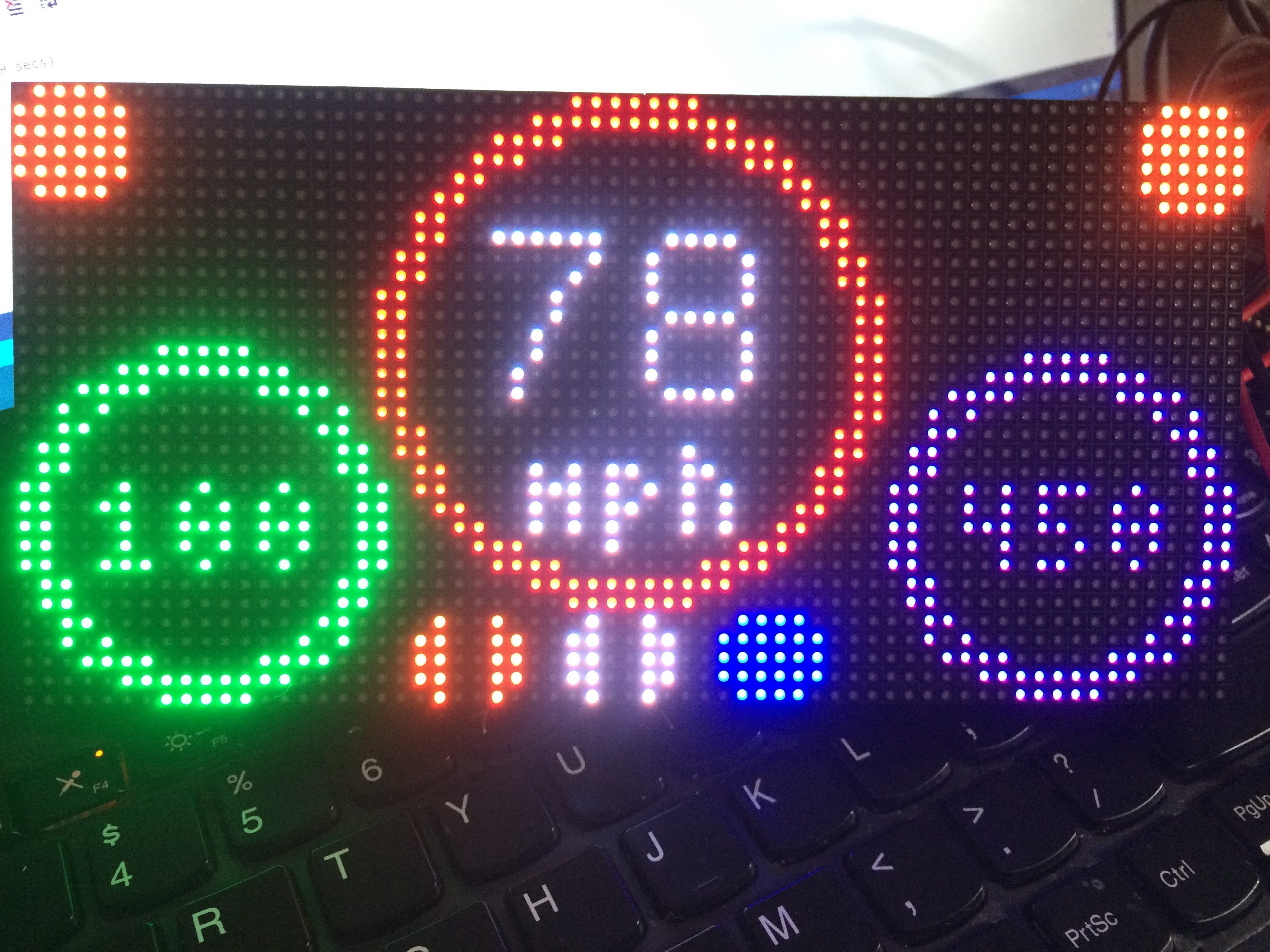
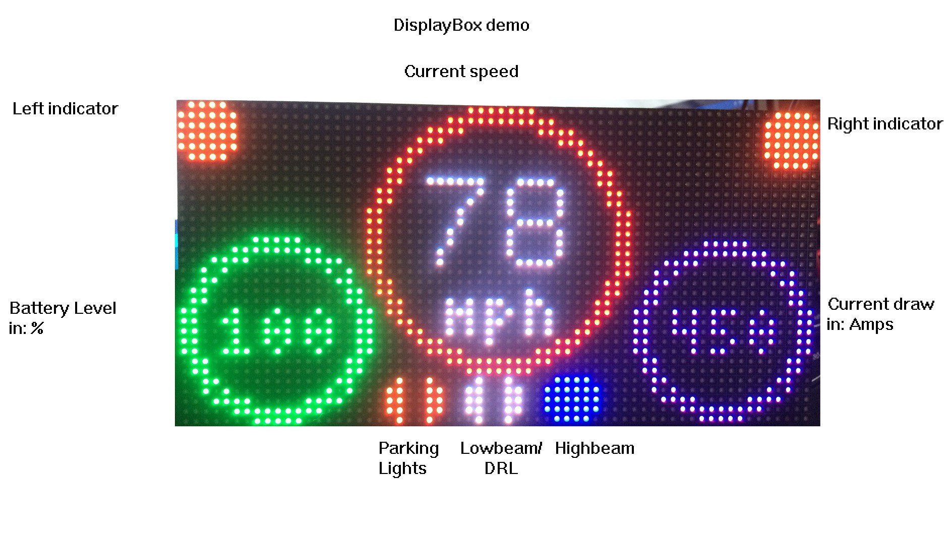
Hybrid Display Idea
I'm currently using a 3mm pitch 64x32 RGB LED matrix as the main display. I am entertaining the idea of creating a hybrid display. When I build the displays and enclosure the matrix will populate the background and in the center will be a tiny high-contrast sunlight-readable color display to supplement data. This idea is still in the brainstorming phase so I'll draw it up once I get a 75% working matrix display.
Software Repository a.k.a. GitHub
I need to keep everything organized and prepare for the project to expand cleanly. I've worked within gihub in the past but never kept up with it. It's time to change that and add code updates to the list of dailies (social updates, code updates, design updates, hardware updates). I'll add repository links to my profile once I get reacquainted with the workflow.
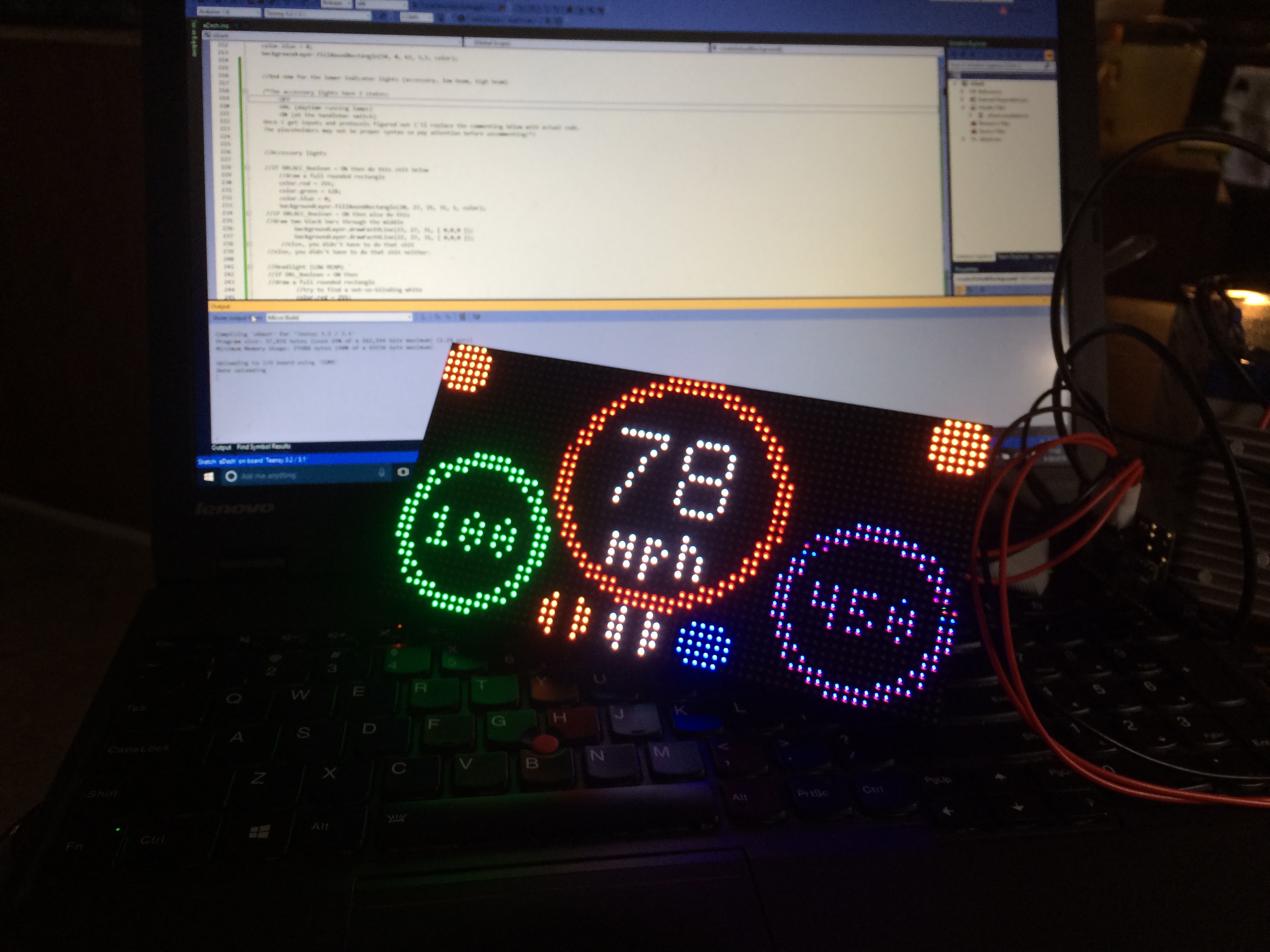
Visual Studio IDE and Visual Micro
I've switched to Microsoft Visual Studio and the Visual Micro extension for my IDE. The official Arduino IDE has gotten a lot better since the switch to 1.6.x. But code completion alone in Visual Studio justified the switch and enduring the learning curve. There are plenty of in-depth tutorials on the YouTube but I'll get into those once the BrainBox is on the table. For now I need a working dashboard for my electric motorcycle project.
-
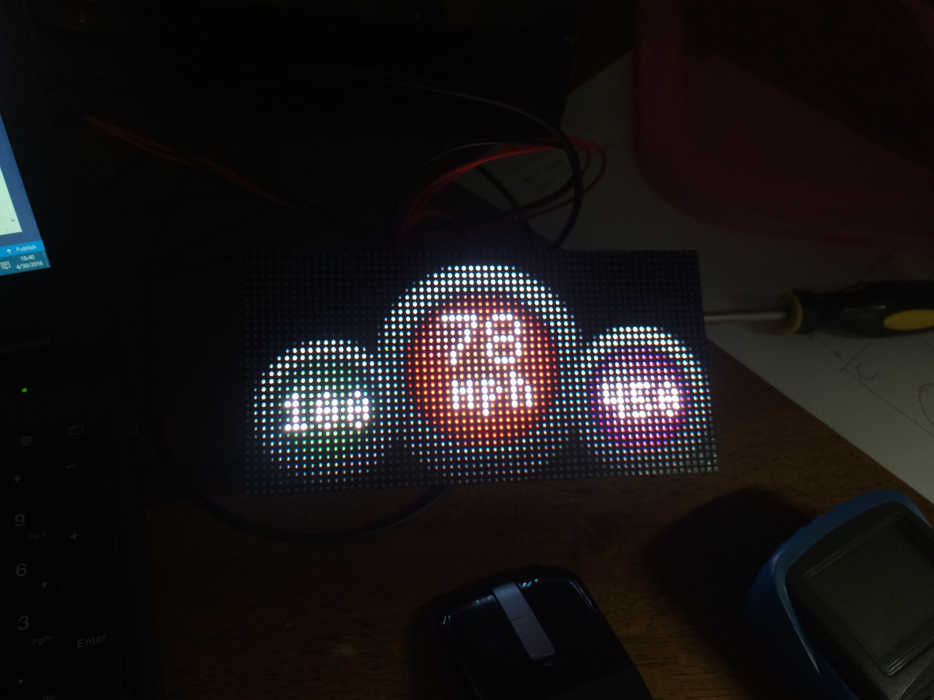
EVBox|DisplayBox:indexedLayer
04/30/2016 at 16:55 • 0 commentsIn a previous log I mentioned I wasn't sure what "indexing" meant. Well, I figured it out now. It's a separate layer that is of a single 24-bit color. Well, indexing in general can be any bit depth. But for the purposes of the SmartMatrix SD Shield that value is 24-bit.
What's also interesting is that I then figured out how to configure different layers. I think this will really add some depth and versatility to the display. I envision possibly mixing GIFS and bitmaps on different layers. Or at the least sprites and bitmaps. And with that high color depth it may prove very clear.
![]()
![]()
-
EVBox|DisplayBox:'const char' Blues
04/29/2016 at 13:28 • 1 commentI am not a programmer!
I can't code effectively at all. They say programming is just like learning a new language and I was terrible at that as well. The way I think my brain works is if I can just touch it. Even in my mind's eye if I can physically manipulate the problem then I can figure it out. Code and math, they're intangible and for decades I've tried to learn and for decades I've been just a beginner. (Note: if i write a question mark in parenthesis (?) it's just my way of using a term that I don't fully understand the meaning of)
Problem
I need to draw numbers on the screen (speed, RPM, temperature, etc) but the function that does this only accepts const char variables and my data contains integers. How do I convert the integers into a string so the function can work?
The SmartMatrix3 Arduino library has a function to draw text on the screen on an "indexed layer". Not sure exactly what the "indexed" means yet but looking at the Layer_Indexed.h file in libraries I see the following:
void drawChar(int16_t x, int16_t y, uint8_t index, char character);
void drawString(int16_t x, int16_t y, uint8_t index, const char text []);
We have the drawChar and drawString functions. drawChar displays a single ASCII character and drawString a text string (which as I understand it is just an array of char). The const part makes the string read-only, and the brackets at the end denotes an array.
Solutions
I've tried a few times to simply convert a two-digit integer into a string, and then pass that string as a variable to the drawString function. I get an error message every time.
invalid conversion from 'char' to 'const char*' [-fpermissive]
Notice the asterisk at the end of that error? I think it has something to do with a pointer(?) and I know pointers are versatile but I still don't understand it yet.
What's Next?
Well, you know how you can bit-bang data on a microcontroller? That's pretty much how my programming works. I'll brute force a solution until I get something that works. It would probably be easier to just post it on a forum somewhere, but the answers I get from those smarter than I only serve to daze and confuse. Well, let's get on with it....
Current test code (04/29/2016 10:09:08)
#include <SmartMatrix3.h>

#define COLOR_DEPTH 24                  // known working: 24, 48 - If the sketch uses type `rgb24` directly, COLOR_DEPTH must be 24
const uint8_t kMatrixWidth = 32;        // known working: 32, 64, 96, 128
const uint8_t kMatrixHeight = 32;       // known working: 16, 32, 48, 64
const uint8_t kRefreshDepth = 36;       // known working: 24, 36, 48
const uint8_t kDmaBufferRows = 4;       // known working: 2-4, use 2 to save memory, more to keep from dropping frames and automatically lowering refresh rate
const uint8_t kPanelType = SMARTMATRIX_HUB75_32ROW_MOD16SCAN;   // use SMARTMATRIX_HUB75_16ROW_MOD8SCAN for common 16x32 panels
const uint8_t kMatrixOptions = (SMARTMATRIX_OPTIONS_NONE);      // see http://docs.pixelmatix.com/SmartMatrix for options
const uint8_t kIndexedLayerOptions = (SM_INDEXED_OPTIONS_NONE);

SMARTMATRIX_ALLOCATE_BUFFERS(matrix, kMatrixWidth, kMatrixHeight, kRefreshDepth, kDmaBufferRows, kPanelType, kMatrixOptions);
SMARTMATRIX_ALLOCATE_INDEXED_LAYER(indexedLayer, kMatrixWidth, kMatrixHeight, COLOR_DEPTH, kIndexedLayerOptions);

const int defaultBrightness = 100 * (255 / 100);    // full brightness
                          //const int defaultBrightness = 15*(255/100);    // dim: 15% brightness

const char speedValue = 20;

void setup() {
  matrix.addLayer(&indexedLayer);
  matrix.begin();
  delay(3000);
}

void loop() {

  indexedLayer.fillScreen(0);

  indexedLayer.setFont(font8x13);
  indexedLayer.setIndexedColor(1, { 255, 255, 255 });
  indexedLayer.fillScreen(0);
  indexedLayer.drawString(24, 8, 1,speedValue);

  indexedLayer.swapBuffers(false);

 }