-
More robust test setup
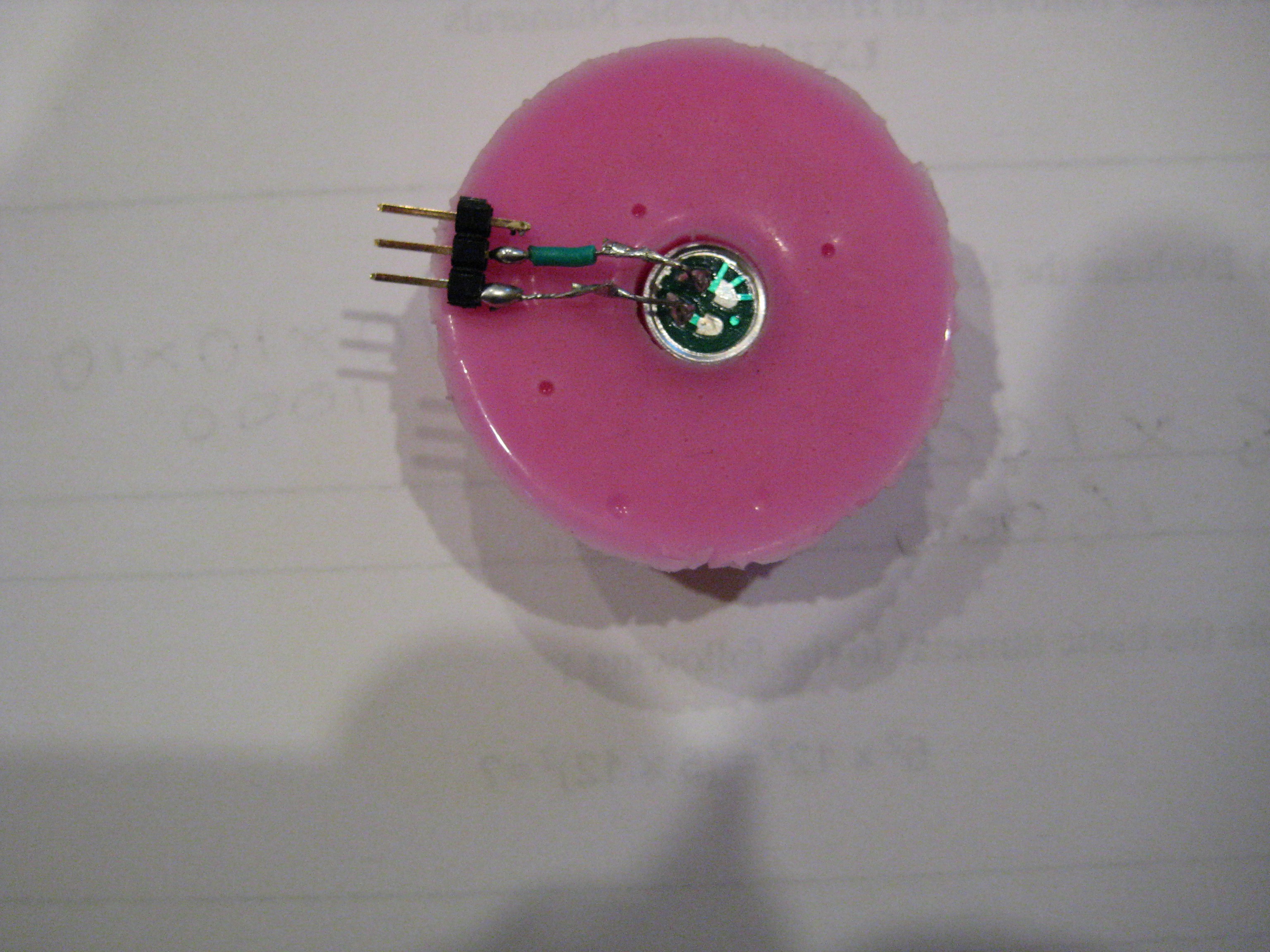
05/02/2016 at 01:54 • 0 commentsI made a mount for the microphone using some 2 part casting silicone (pinkysil). Below is showing the first step where Ithe microphone sits:
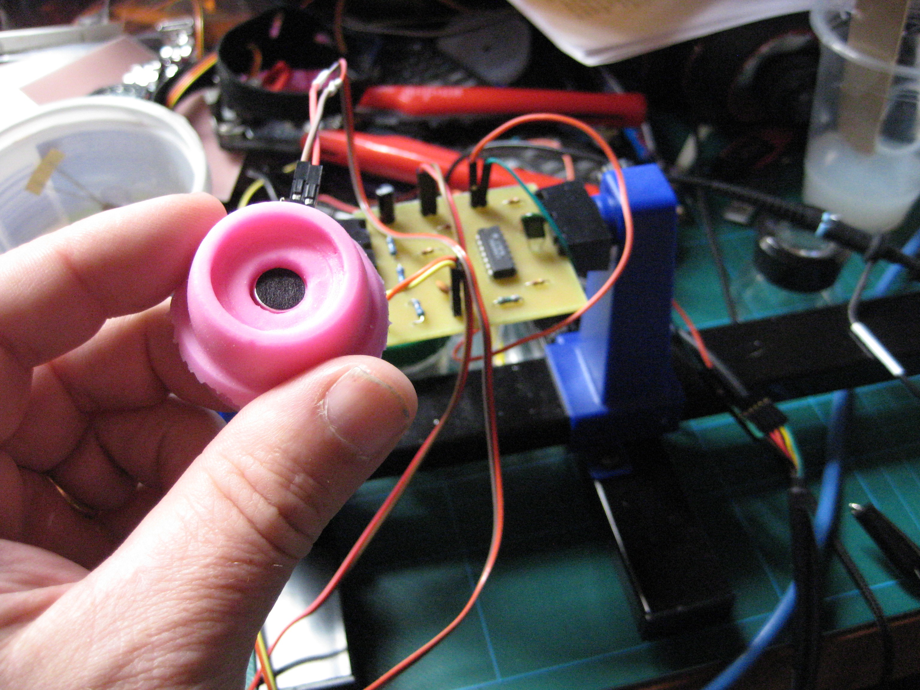
Then covered the back of the microphone with more silicon.I also made up a PCB version of the filter/amplifier. Below is the finished silicon rubber probe (looking from the front of the microphone and the circuit board:
Next time I will use a different header setup for the mic probe. When pushing on wire sockets to the probe, the header pins tend to slide into the sensor rather than into the socket as the silicon rubber doesn't provide much resistance to hold the pins - bit fiddly to connect it as it is now.
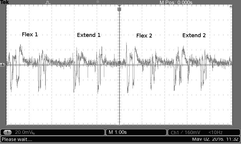
I then did a quick test. I fixed the probe to my bicep using velcro straps and measured the output for a series of bicep flexes. I held a weight so the extension would be against resistance.
Video of the test and oscilloscope plot that was recorded below:
![]()
This is looking as if it has potential :)
-
Is it feasible?
04/30/2016 at 02:04 • 0 commentsI am not an electronic engineer so a lot of the process below is how, as an amateur, I go about implementing and testing my ideas. Basically a lot of trial and error and experimentation as I don't have the depth of knowledge or training to do otherwise so for those with better skills, forgive me :)
First step was to see if I could get a signal from muscle movement using an acoustic sensor.
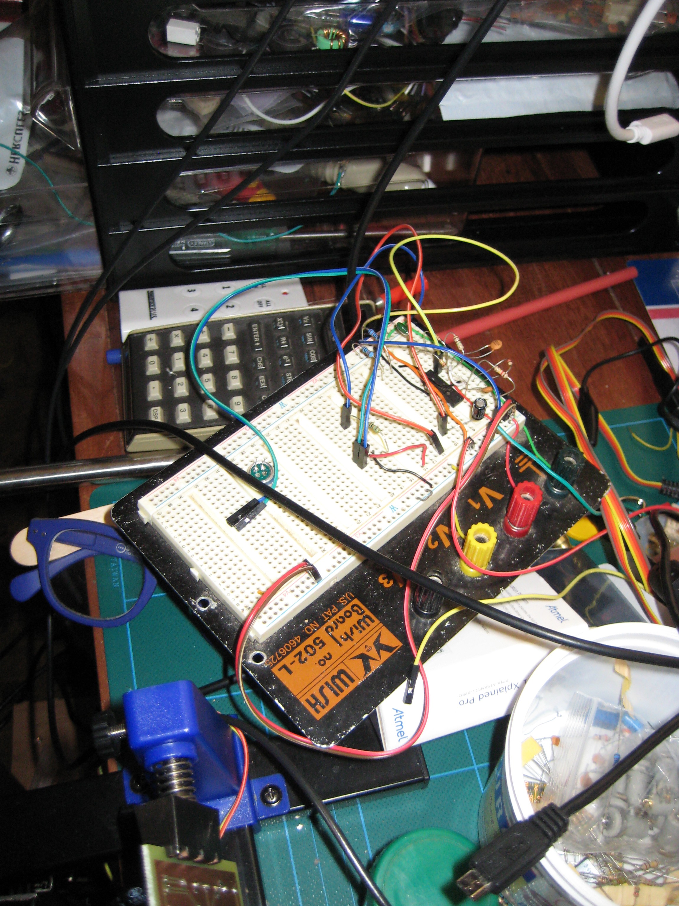
I used a small electret microphone and a low pass filter/amplifier (MMG signals from my reading are typically < 200Hz) The output was displayed on an oscilloscope to indicate if what I was getting corresponded to actual muscle activity.
Setup
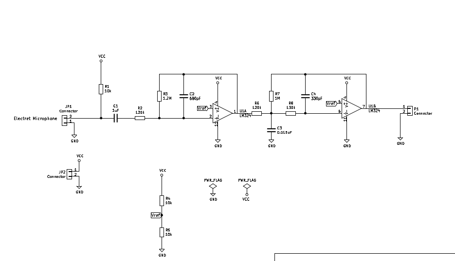
The amplifier/filter is implemented using 2 op amps from a LF347 quad op amp. I used the web site http://www.beis.de/Elektronik/Filter/ActiveLPFilter.html to assist in selecting suitable values for a filter and came up with a simple butterworth low pass filter that hopefully would attenuate signals > 200Hz
![]()
I built up the circuit on a breadboard
I injected a sine wave from an old audio signal generator (suitably attenuated) into the circuit in place of the microphone and viewed the output for various frequencies on an oscilloscope. It showed the circuit was acting as a low pass filter, as I changed the frequency, the output amplitude dropped noticeably for signals approaching 200Hz and greater.
Rough Test
I then connected the microphone and placed it on the the top of my forearm over the muscles that flex the wrist upwards (like when you are indicating a 'stop' hand sign).
Viewing the output on an oscilloscope I got a trace with amplitude changes that visually seemed to correlate with my movement of my wrist.
Extension against resistance (I tried to rotate my wrist against the underside of a table) produced a qualitatively different signal from free extension movement and both gave different results from relaxing the wrist. Similarly sustained clenching of the wrist upwards gave a qualitatively different signal from the others. The spikes in the trace corresponded to starting and stopping of movements with some lower amplitude oscillations occurring during movement.
The signal was quite noisy but this didn't surprise me, I was holding the microphone against the skin lightly with my fingers or by the wires from the microphone and this was causing a lot of unwanted mechanical noise - it would pick up if I accidentally slid the microphone across the skin and it was sensitive to finger grip pressure etc.
It also involved some contortions to avoid pulling wires out of the breadboard or off the microphone as I moved.
Conclusion and next steps
Despite the noise, the correlated spikes and patterns seemed to indicate that I can measure MMG signals, certainly it worked well enough for me to decide to go to the next step: work out a way to better mount the microphone against the skin (to be more secure and limit unwanted noise) and also to make up the filter onto a PCB so it is physically more robust. This will allow me to better experiment with the technique.
Acoustic Myography/Mechanomyography Experiments
Experiments to investigate how muscle activity can be measured using acoustic signals generated by muscles.
 Jonathan Kelly