-
Ups and downs
05/05/2016 at 21:39 • 0 commentsThe block fried.
I've left it alone after the lock, to write the previous log and then returned to the workshop where a smell of burned resistor worried me. The current was bumped to 2.6A, 2A more than normal.
Then, this happened.
http://hackaday.com/2016/05/04/a-rubidium-reference-for-discrete-component-clocks/
-
Lock achieved
05/02/2016 at 06:55 • 0 commentsAnd achievement unlocked :-)
I don't know how long it took (10 minutes ? I'll have to measure next time) but the "lock" output has finally been asserted.
Parameters: Ta=18°C, 15V, 0.60A when settled.
The unit rests on bubble wrap to insulate against heat losses through conduction with the table, yet the other side is exposed to free air to prevent overheating. The question of insulation vs heatsinking is pretty complex but a mixed approach should work. Too much heatsinking and the unit will draw too much current to heat the Rb lamp to >100°C and locking might take a very long time, if ever.
I measured again : from a cold start, the block took 13 minutes to lock while the current was 0.7A (not yet settled to 0.6A).
This is pretty long and it could be a sign of old age (or a cold room), but this is not critical for my occasional needs. Maybe I'll have to get it recalibrated, or buy a second one... one day.
-
Where to get some interesting frequencies ?
05/02/2016 at 02:04 • 0 commentsThe seller's description of this object is "FEI fe-5680b rubidium oscillator With 1pps 20mhz output ONLY/10mhz NEED to MOD" and it includes pictures showing the PCB. The "NEED to MOD" part makes it clear that the box must be opened.
The 1pps signal should be directly available on pin 5 of the HD15 connector. The only catch is that it only appears when the clock is locked. Some more practical considerations are provided in "I can't see the 1pps output!".
(I haven't see it yet so I presume I've not turned it on long enough for a lock)
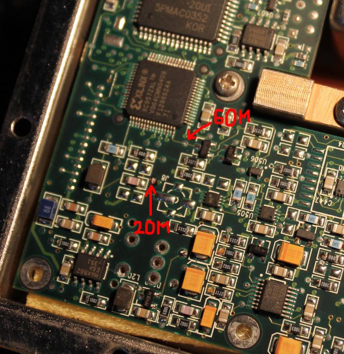
The advertised 20MHz is explained by the seller : find it on the PCB and solder a wire.
You may even get some 60MHz on the other side of the board :![]()
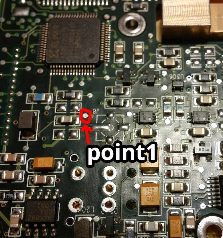
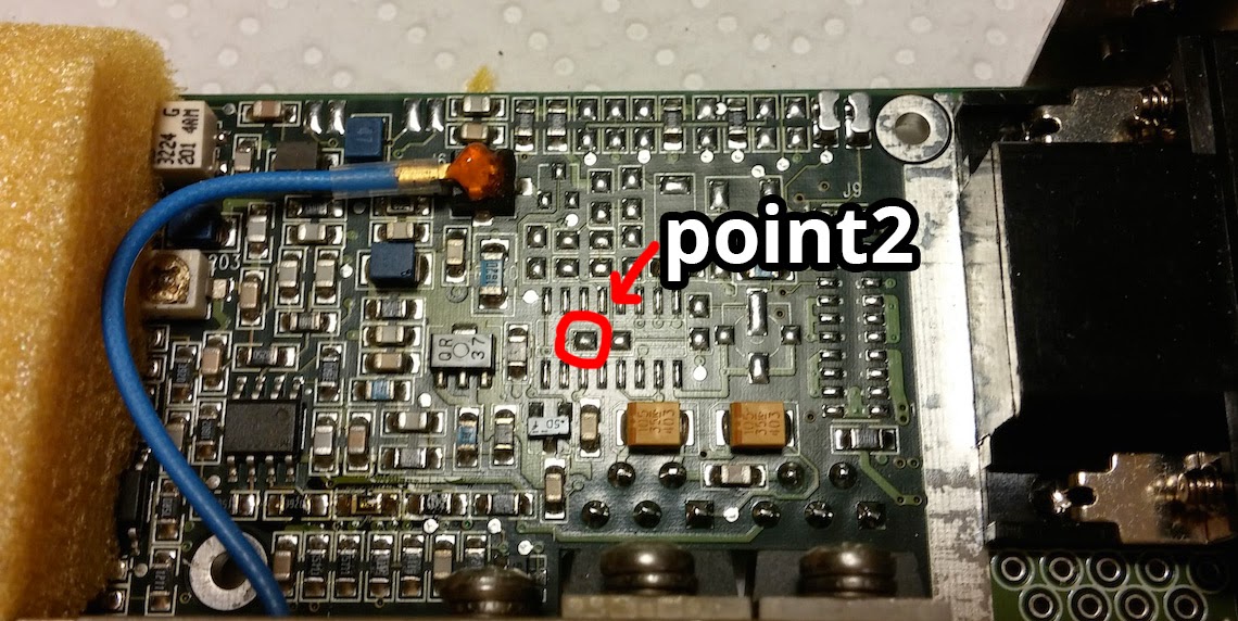
![]() So far, so good and I've found the 20MHz as expected.
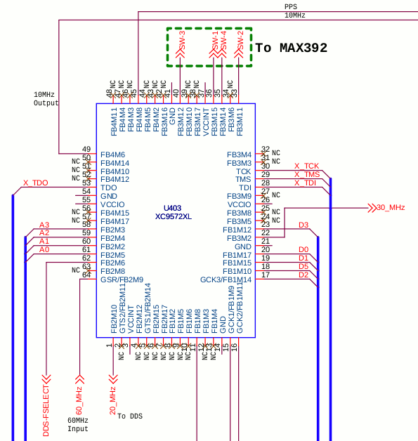
So far, so good and I've found the 20MHz as expected.Now, somewhere (I'll probably remember the link one day) I found the schematic (somewhat reverse-engineered) of the model A. This is not model B but some similarities are striking. In particular there is the same Xilinx CPLD with those interesting signals:
![]() The CPL gets 60MHz and outputs 30MHz, 20MHz, 10MHz and 1pps.
The CPL gets 60MHz and outputs 30MHz, 20MHz, 10MHz and 1pps.Several attempts have been made to dump the CPLD's configuration but that's not really interesting, as the lower-left corner shows the interesting part: this is the 60MHZ input (coming from the clock generator).
Is this valid for my model B?
The probe peeked at that pin and found the expected high frequency signal. Looking around, I found that this signal is available on a testing point (just like the previous 20MHz), so there is no need to hack the other side of the PCB !
I also notice something else : this signal appears to be coming from the collector/drain of a transistor, so it might be already amplified and this would reduce interference with the clocking subsystem.
-
Providing the internal 5V on the HD15 connector
05/02/2016 at 00:56 • 0 commentsThe FE-5680 family has so many variants !
Some need an external 5V power supply, others generate it internally.
The external supply makes sense to save a buck or two on a buck (pun) converter and its parts. The other solution is good to keep the modules count down. So the parts of the converter may or may not be soldered.
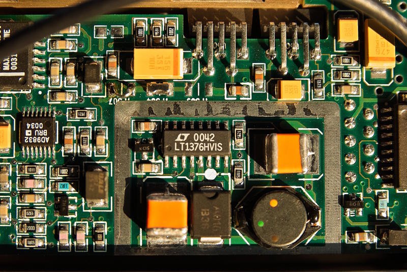
This is illustrated on figure 4 of http://www.ka7oei.com/10_MHz_Rubidium_FE-5680A.html where one unit has no parts (and gets a replacement) and the other is populated.
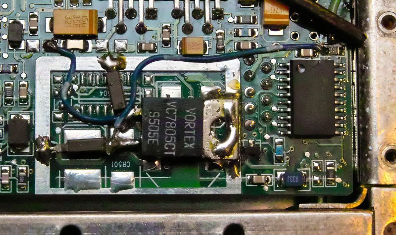
More interesting is the hack that brings the internal 5V to the main connector. For reference, the picture is there :
![]()
Now, I had to deal with two things
- I don't have this model, the connector and the PCB are different.
- I forgot where I found this picture.
But in order to get the lock signal conveniently, I need some voltage to pull up and/or light an LED. So let's find which jumper goes to pin 3 of the HD15 connector. Fortunately
- The board is not radically different
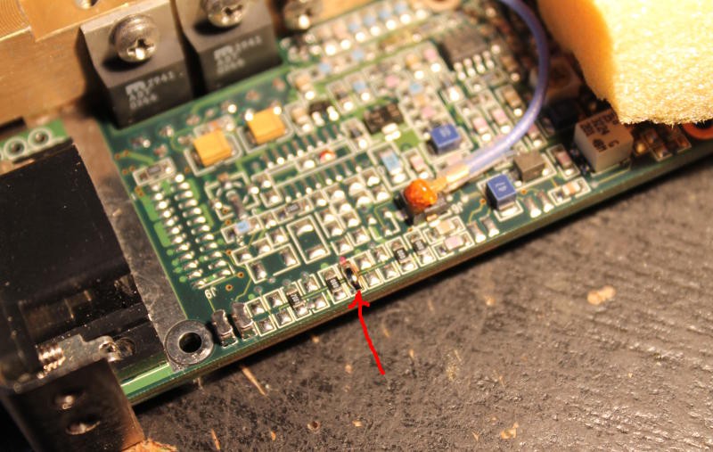
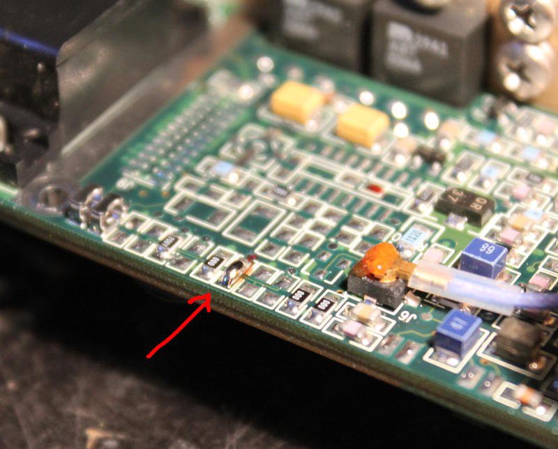
- I had a vague souvenir that there was a pad to short near the edge.
What did I do ?
I wired a 100K resistor to the 'scope's probe test point (2Vpp square) and hooked the signal to the HD15 pin. Simultaneously I probed the pads that I thought would be the best candidates.
Examination of the PCB near the HD15 pins shows that there is at least a filtering capacitor (and even probably a Pi C-L-C network). So of course the signal would be distorted but the frequency is low enough to pass and appear as some sort of sawtooth.
After carefully checking I bridged the pads with solder and I got 5V !
Of course, don't do this at home, kids. Since many models are different, the configuration might be somewhere else, see how it changed from model A to model B !
Ah yes this hack is also explained in Ruby Writeup (I mirored the PDF here). I have read his explanations and this hack was not clear to me at that moment, but I memorized it. When I needed it, half a day later, it was obvious I had to do it too. So no, I didn't invent this ;-)
-
Links and resources
05/02/2016 at 00:45 • 0 commentsThis log summarises the documents I have found about the FE-5680 family.
- The auction: http://www.ebay.com/itm/301905937814
(the provided informations are not well organised but they can be somehow understood) - The manufacturer: http://freqelec.com/rb_osc_fe5680a.html (no useful info there)
- Some threads where this unit is examined: http://www.eevblog.com/forum/testgear/fe-5680b-1pps-to-10mhz/
- Clint's inspiring hacks : http://www.ka7oei.com/10_MHz_Rubidium_FE-5680A.html
- EEVblog#236 - FE-5680A Rubidium Standard Teardown (there are a few other 5680-related videos on youtube, have a look)
- Some appearances in the time nuts forum https://www.febo.com/pipermail/time-nuts/2015-September/094009.html
- http://time-nuts.febo.narkive.com/0Fm6P0bH/fe-5680a-1-pps-photo
- https://drive.google.com/file/d/0B9NVwHoWDHKMWklwcU5qQlBtc2c/view?usp=sharing
The references lead to other resources !
http://gerrysweeney.com/build-a-10mhz-rubidium-frequency-standard-and-signal-distribution-amp-for-my-lab/
http://www.rhodiatoce.com/pics/time-nuts/FE-5680A/FE-5680A_schematics_v0.1.pdf
http://www.wa6vhs.com/Test equipment/FREQUENCY STANDARDS/FE-5680A/5680 TECH MANUAL.pdf
- The auction: http://www.ebay.com/itm/301905937814
Hacking a FE-5680B rubidium reference clock
Sold as "1pps only", this affordable eBay find is a playground for reverse-engineering, with a few useful laboratory applications.
 Yann Guidon / YGDES
 So far, so good and I've found the 20MHz as expected.