-
In principle it works, but I failed...
08/15/2016 at 08:01 • 0 commentsSorry for the long delay, I was busy and had no time to write a blog entry.
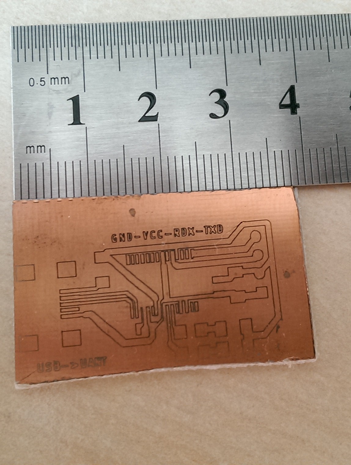
As a test I used a schematic for an FTDI Serial to USB adapter I found online. It has very small dimensions (1.9 x 3.5 cm) and a SSOP28 footprint on it with 0.5 mm pin pitch.
The first try was already ok, but not really usable since some of the very small pads were to small due to some inaccuracy.
![]()
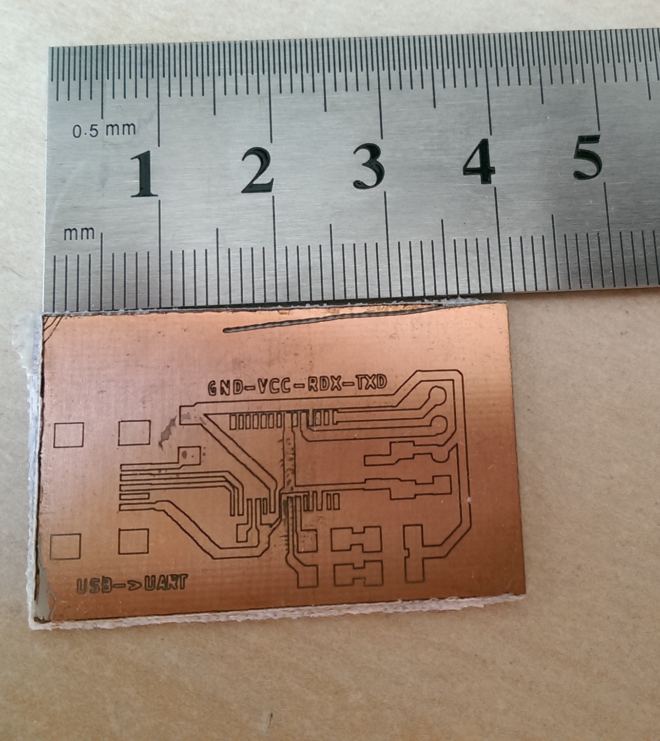
The second try look better but it was still not usable.
![]() With these results in hand I realized that my laser plotter is simply not made for such small structures.
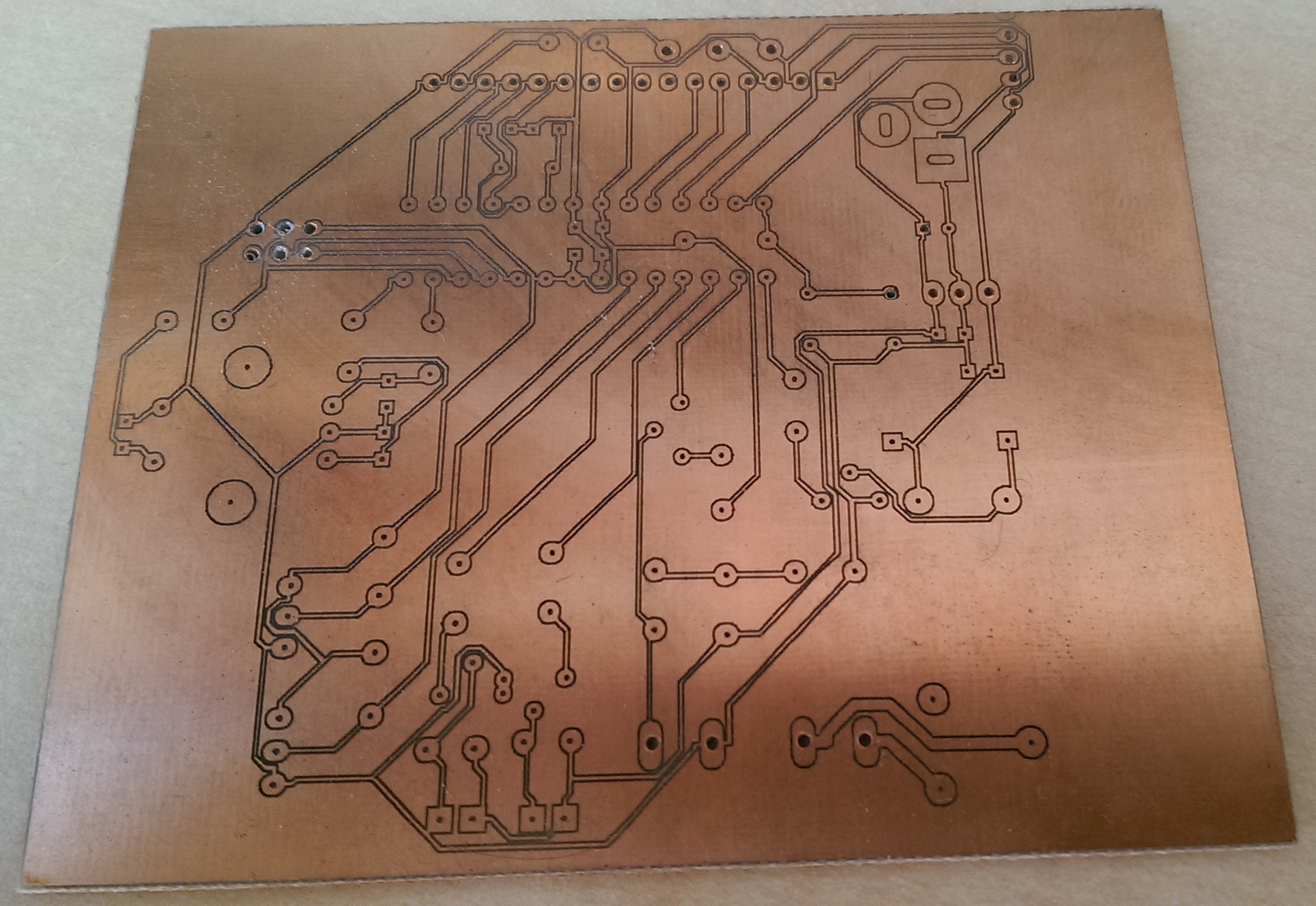
With these results in hand I realized that my laser plotter is simply not made for such small structures.Nevertheless I tried to make bigger PCBs with it. I choose the layout of one of my current projects, converted it to DXF and gave it a try.
![]()
In general the PCB looks quite ok, but that's it. If one looks closer some of the diagonal tracks are uneven and smaller as they are supposed to.
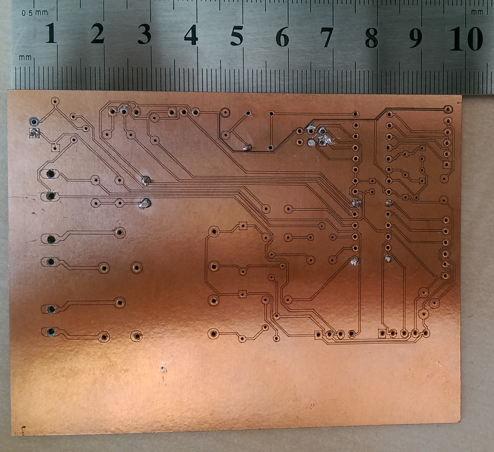
I gave it a last try with another layout and this one is the best so far. The tracks have the correct width and are not broken.
![]()
A drilled a view holes and tried to solder some of the parts, mainly resistors and connectors. As you can see on the pictures the joints are not very pretty, although I would say of myself that I can solder quite ok. The main problem was the heat dissipation: My 80 W soldering station with a needle tip (400 °C) could not heat up the pad high enough to get the solder to flow nicely. The second problem was the 0.1 mm etched gap between the pad and the rest of the PCB. It was very difficult not to connect these two. The solder would just flow over the gap. Maybe the last problem might be fixed by applying a solder stop coating.
Conclusion
My laser plotter is not made for such small structures. As I understand the situation, it is to big and thereby to inaccurate since small inaccuracies sum up and result in 0.5 mm deviation. For fun projects where accuracy of > 1 mm is not needed like engraving in wood, cardboard or cutting felt and foam it is just fine.
Problems that have to be fixed
- To small tracks: One should use the tools correction parameters in GCODE (G40/G41/G43) to get the correct track width. The laser beam was focused to about 0.1 mm. Unfortunately GRBL 0.9j does not support these. Maybe these can be hardcoded in the GCODE / DXF file with software.
- Inaccurate tracks: My guess is, that this particular problem only can be fixed by building a smaller plotter. If one would build a plotter lets say in a DIN A4 (210 x 290 mm) format the small inaccuracies would not sum up as bad as in my 400 x 550 mm machine.
Laser power and PCB etching
Just a quick overview over the settings and materials I used for testing
- Laser: 405 nm laser diode, 100 mW max power. In GCODE I used the paramter S=5, which relates to about 5 mW laser power. Output powers up to 20 mW worked fine, but you have to set a higher feed rate.
- Feed rate: Depending on the laser power I choose f = 100 - 300 mm / s.
- PCB etching: To remove the exposed photo sensitive layer I used sodium hydroxide (1 g / 100 ml water). In about 30 - 90 sec. all was gone. To remove the copper layer I used HCl/H2O2. Be careful with this mixture, it is very corrosive (I am a chemist by training and know what I do ..). I also tried sodium persulfate (Na2S2O8, 200 g / l , 40 - 50 °C) which is almost harmless and works fine also.
-
Nema 17 Vibration damper
05/23/2016 at 19:36 • 0 commentsWhile calibrating and testing the new design, the vibrations from the motor were quite annoying.
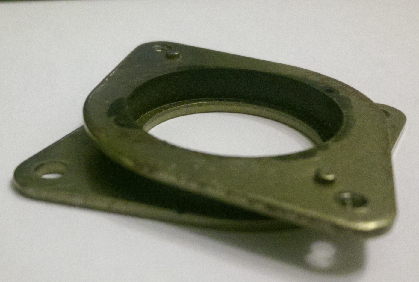
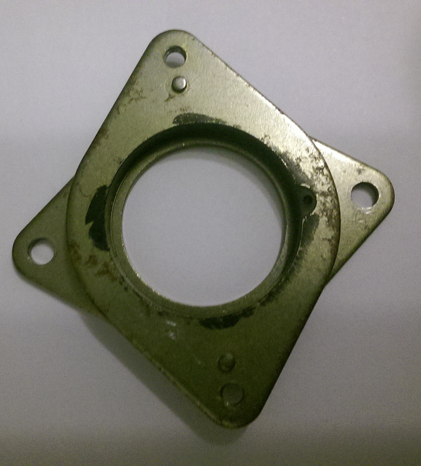
I did a little bit of research how to reduce the vibration from the motors into the frame and found vibration dampers on eBay and Aliexpress. Since they are quite cheap, I ordered 3 of them.
These dampers are very simple: a rubber ring is melted between two shifted junctions for the motor and the holder.
![]()
![]()
The noise reduction is amazing, the plotter runs very quiet even while fast jogging to a certain position. Definitively worth the money. However I could not see any difference in accuracy yet.
-
The rebuild
05/03/2016 at 18:58 • 0 commentsGeneral
In the first version of my plotter I used single aluminum rods for the X and Y axis and short LM8UU linear bearings. In this improved version I am still using a single rod for the X-axis but made from V2A stainless steel and SC8UU linear bearing platforms. The advantage from V2A over aluminium is, that it barely bends at all when the Y-axis is in the middle of the working area. To achieve more stability on the X-axis and hopefully less wobbling, two SC8UU linear bearing platorms were used per side with little spacing. In contrast to the first version of my plotter the Y-axis is oriented in a horizontal instead of a vertical way and two linear bearing platforms were used to move the laser.
Motors
First I used my old China Nema 17 from the first build but was not very happy with. The overall results were better but not as much as I though. The only variable left to replace were the Nema motors. I chose to by new ones from omc-stepperonline.com via eBay. With the new motors in I think the plotter is as precise as it will get. Compared to the old ones there is a huge difference in quality, noise reduction and accuracy. TIP: Do not be cheap on motors !
Belt fixation
I used two pieces of 2 mm aluminium to clamp the GT2 belt on the Y-axis. On the Y-axis I fixiated the belt with two flat washers and the 4 mm screws for the liear bearing platform. This did not necessarily improved the overall precision, but it definitively looks better.
Wood working
As in the first build I used Multiplex ply wood for all mounts.
Electronics / Wiring
I have not changed anything on the driver board or connections from the first version. I attached the KiCAD schematic on the basis of which I want to build a proper PCB in the future (Feel free to use this as a basis for your own design). The complete KiCAD project is attached to this blog. However I have not done the routing yet. The KiCAD A4988 stepper driver carrier module can be found on the Pololu page.
Software
Nothing much has changes here. I upgraded the Arduino from grbl 0.9i to 0.9j. Since 0.9i the G40 command is supported, this might come in handy for engraving tiny structures.
Yet another laser engraver / cutter 2
I improved the mechanics on my first laser plotter to get a more accurate machine to make PCBs with it.
 With these results in hand I realized that my laser plotter is simply not made for such small structures.