electrobob
-
Mini assembly run
05/28/2016 at 20:47 • 0 commentsI have assembled 6 more devices, for a total of 8. Collecting the parts, assembling them and programming the 6 took slightly less than 1 hour, that is 10 minutes for each device. Not bad.
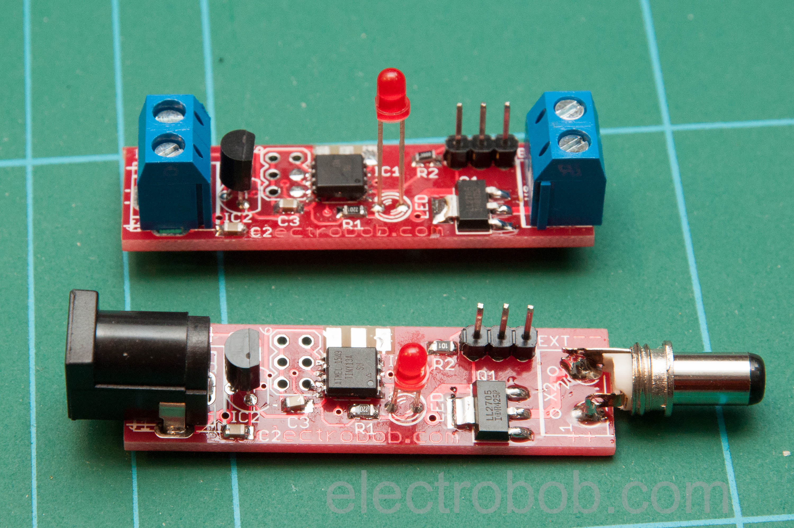
![DSC_5659]() Notice the 2 ways to connect the power, supported by the PCB: using terminal blocks or DC jack. Of course, any combination of the 2 is possible. I prefer terminal blocks for all the devices that are out of warranty and I can cut the cord to as this allows for a more optimal placement, such as at the middle of the cable.
Notice the 2 ways to connect the power, supported by the PCB: using terminal blocks or DC jack. Of course, any combination of the 2 is possible. I prefer terminal blocks for all the devices that are out of warranty and I can cut the cord to as this allows for a more optimal placement, such as at the middle of the cable.![DSC_5664]()
And finally, some tests with the most relevant type of device: the router. Disclaimer: this is not the router it will be used for, fortunately this can run OpenWrt.
![DSC_5645]()
Camera installation coming soon… and possibly a 3d printed case, although i have some project cases that fit the device nicely and that is a faster way to get things done.
Project is now complete: will report in a few months with the performance of the device!
-
Parts are here and…
05/28/2016 at 09:59 • 0 commentsIt appears I have accidentally ordered the wide version of the SO8 package for the tiny13. It has been [5 years] 0 days since the last wrong part purchase. The pitch is the same, so I will probably get around this by bending them.
![DSC_5640]()
-
First one assembled
05/23/2016 at 19:33 • 0 commentsThe first device skips the 5V regulator, as I am testing it with a raspberry pi. Everything is red, even the LED. I began to test it for the raspberrry pi as this needs the additional python software required to shut-down the pi safely. I am thinking to implement the functionality of a power button as well, will be a simple one, since the Pi does not have such functionality.
![DSC_5624]() To contact the side ISP connector I use a home made PCB with a simple 90 degrees connector with pins slightly bent
To contact the side ISP connector I use a home made PCB with a simple 90 degrees connector with pins slightly bent![DSC_5627]()
And brief tests with the Pi, shutdown during the warning time works smoothly.
![DSC_5632]()
-
PCBs arrived
05/22/2016 at 09:47 • 0 commentsI made the PCBs at Elecrow, and due to the small size they sent quite a few extras. Time to get soldering
![DSC_5615]()
![DSC_5618]()
-
Schematic and PCB
05/05/2016 at 09:49 • 0 commentsI finished the board and sent it to the fab. Schematic and PCB rendering below. Files are available at GitHub. The usual 5V regulator with fool proof diode ensures a good 5V supply for the ATTiny13 micro, up to 35V input. There are no worries for powering the device from 5V directly, at the low current consumption it will get about 4V, enough for proper operation. But of course, you can totally skip the regulator in case of a 5V supply. A IRLL2705 logic level NMOS takes care of switching the load. And the brain is a small 1k of flash micro, the ATTiny13.
Your typical LED insures a nice blinky to tell you everything is working. The same output is going to intelligent loads like the Raspberry Pi: 2 minutes before the reset the LED will stay constantly on, to tell it to shut down. The same pin is used bidirectionally: if the load will pull it to ground, that is a sign that it should be powered off soon, so the AutoResetRRR will cut the power after a delay.
![autoresettrrr_schematic]()
![auto resetter board]()
-
The proto
05/03/2016 at 22:08 • 0 commentsThe protoThis is the first device I made on a bread board, but the PCBs are already mostly designed. So far the software is incomplete, but the reset time-out is working. The blue LED is the one that will blink, while the green one simulates the device.
![DSC_5567]()
AutoResetRRR
A project out of frustration. Automatic reset for misbehaving hardware.