Tina Belmont
-
Still Fighting Autodesk Fusion 360
08/16/2016 at 19:49 • 0 comments![]()
Parametric modeling has so very much promise. Change a single value and your whole model updates perfectly! What's not to love!
Lots.
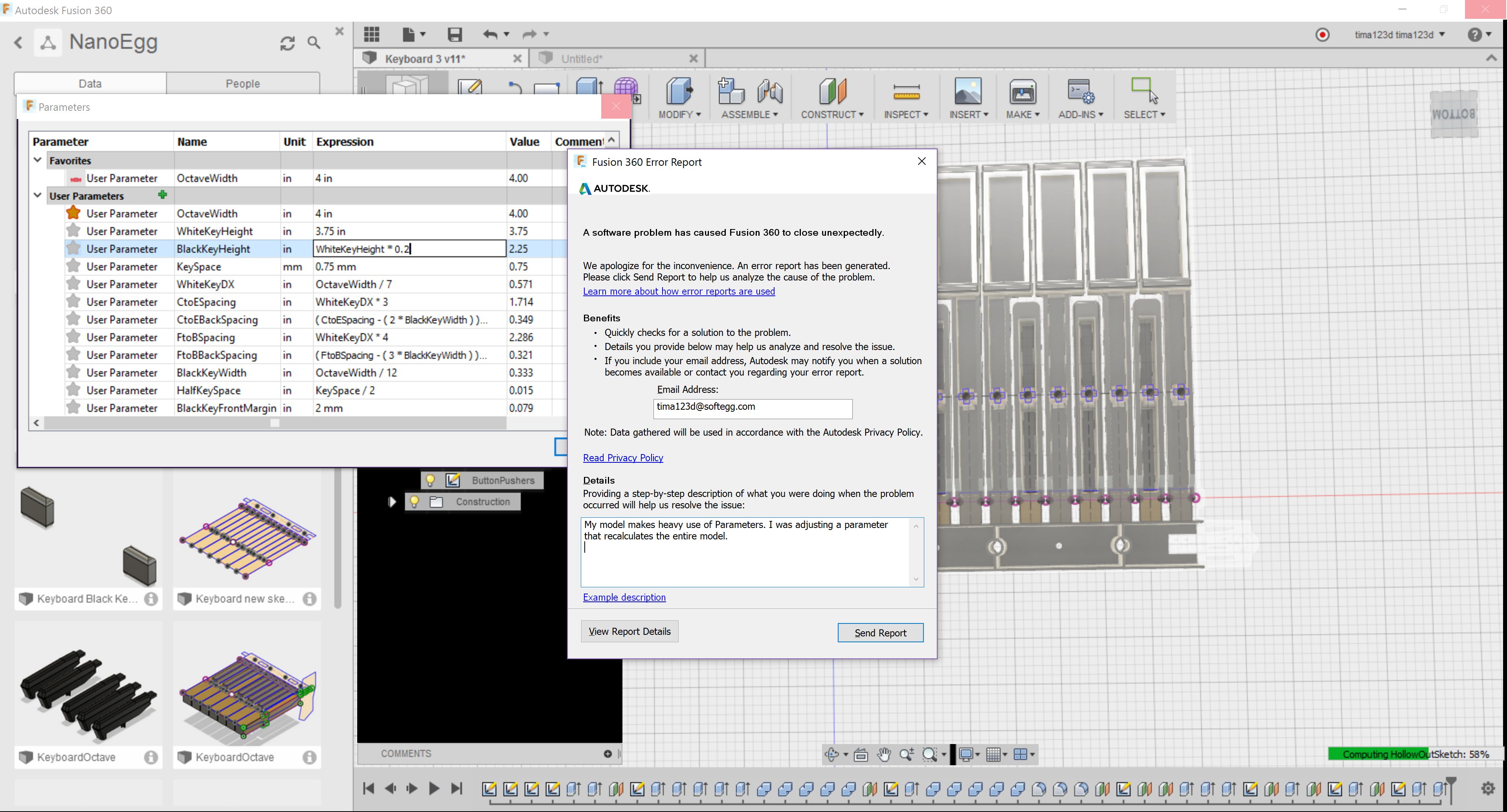
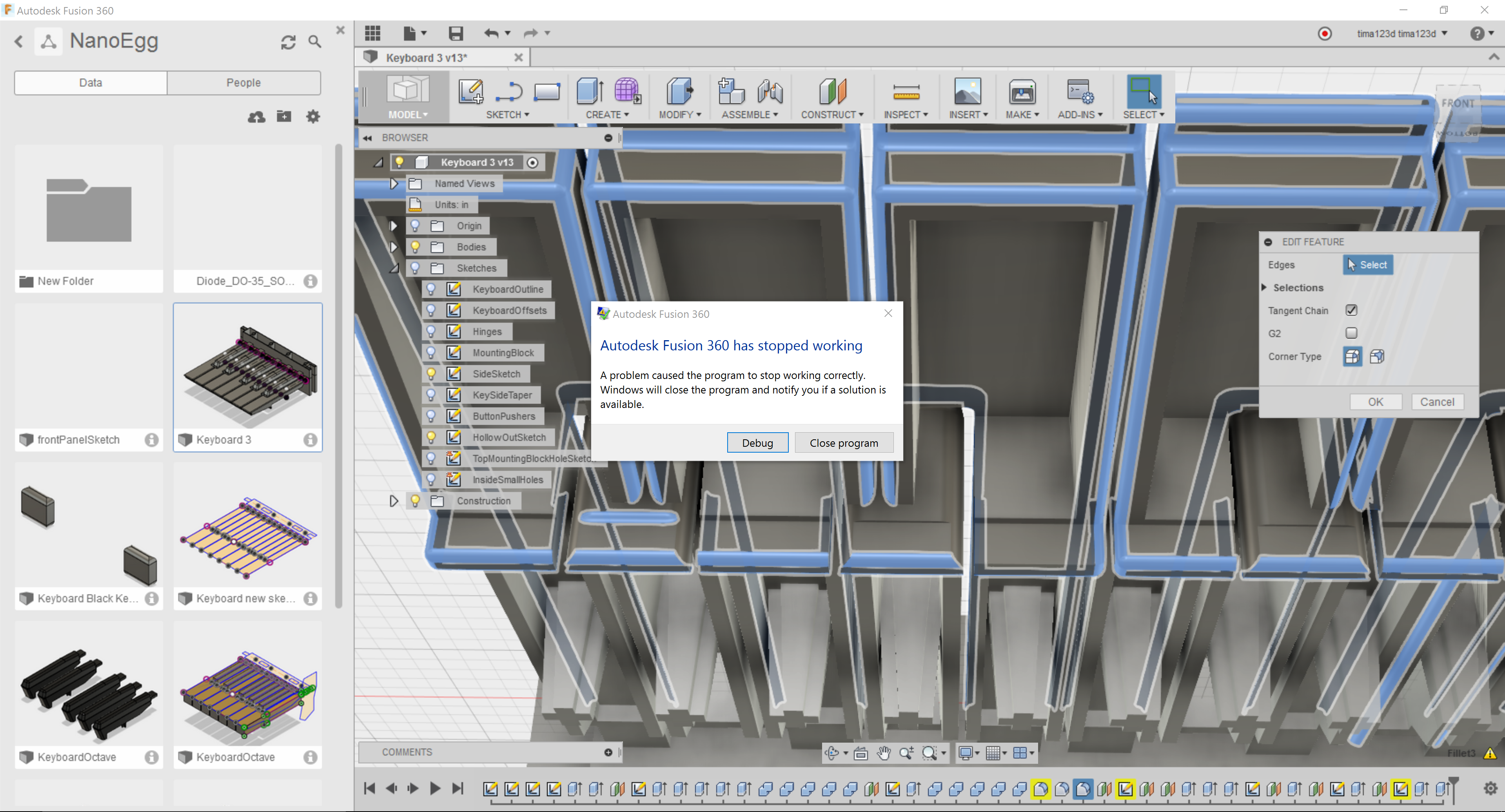
So it is unfortunate that none of the software I've been able to try works reliably. I'm still fighting with Autodesk Fusion 360, and while it is nice in many ways, it seems to be bad at recalculating all of the dependencies in a heavily parametric model. So bad that it will crash on a fairly regular basis. When it isn't crashing, it is deforming my model in strange ways every time I try to update a parameter. I can do a lot of rework to get one parameter to work, and then the next one still breaks the model very reliably.
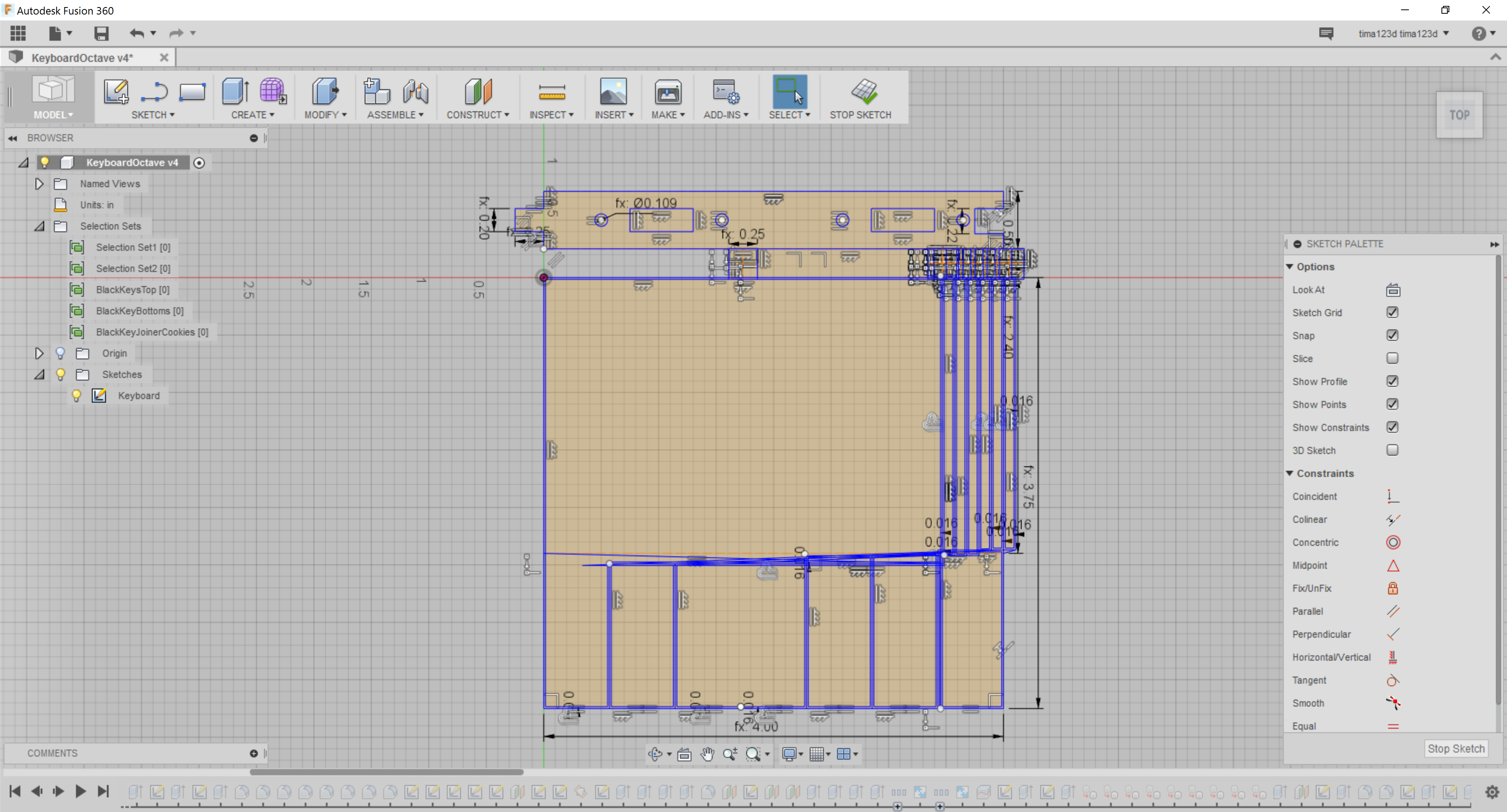
The only real advice I have to offer is to avoid trying to use constraints to calculate your sketches. By all means, use constraints like vertical/horizontal, coincident, perpendicular, and parallel. But avoid using "equal" on a long chain of items to get the spacing right, or midpoint. Instead, use "Parameters" to calculate the position using your own math, and just add a dimension to attach that value.
Be aware that "Offset" will use the value of a parameter, but not actually refer to it until you click on the dimension for the offset and add the parameter again.
The only way to have a sketch refer to something on a sketch or another body is to do a projection. The latest update seems to do this automatically, but it still is the same thing. Use these sparingly, especially when projecting edges from bodies, as I've noticed troubles with them not updating. It is better to project from another sketch than from an edge on a body.
Constraints applied to a projected line do not seem to propagate backwards through the history chain, which can be very handy in forcing it to update correctly. You can make layers of sketches, each fairly simple, that proceed from the projected output of the previous layer. Again, less use of projection is generally better, but this is one place that it might help you get around the terribleness of the recalculation engine.
Also, test your Parameters by changing them often and making sure the sketches and model respond as expected. It is a lot easier to fix the constraints as you do them than have to walk back through the history and try to change things after the whole model is done. Easier, and less prone to crash.
I have learned all of these things, and yet I still keep making the mistake of trusting the software to work. I am a fool.
![]()
-
Autodesk Fusion 360: The Honeymoon is Over
08/12/2016 at 21:34 • 0 comments![]()
Evidently I am now an unpaid, unofficial tester for Autodesk. Wasn't my intention. I just needed to use some CAD software. But nothing ever works perfectly... here are links to the various bugs filed, features requested, and questions asked I have posted since I embarked on using the Fusion 360 software.
"Offset" does not retain Parameter reference
"Sketch Geometry is Overconstrained"! Won't add new constraints...
Screencast Interface too small for 4k Monitor
Can't snap to entities in other sketches
Select multiple, non-contiguous entities for "offset" and similar commands
Remember last settings for commands like "Offset"
Editing dialog for all elements, from sketch up
Sketch elements in hierarchy treeview
Block rubberstamp for repeated elements in sketches (like Solidworks)
-
New Keyboard Test
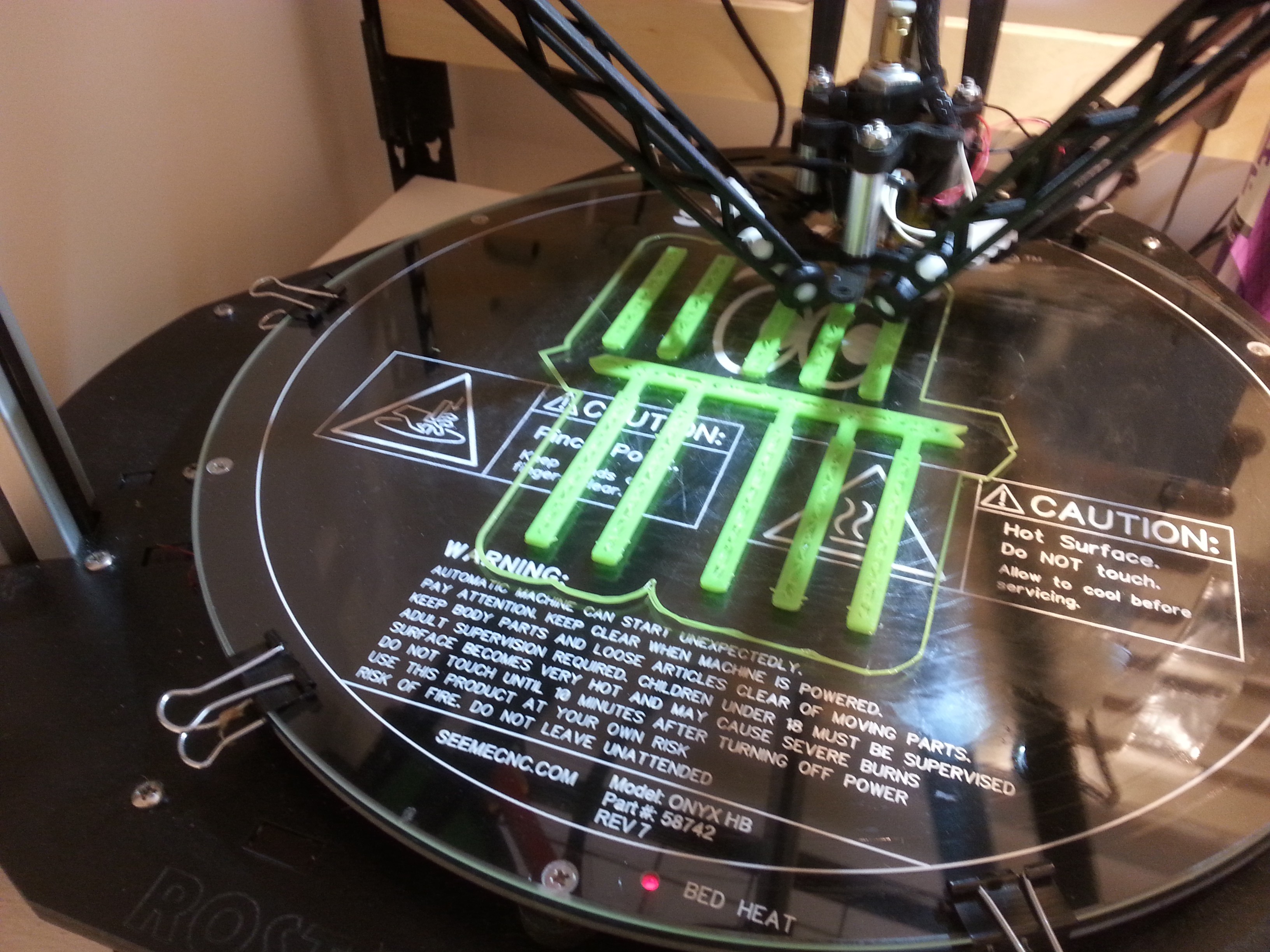
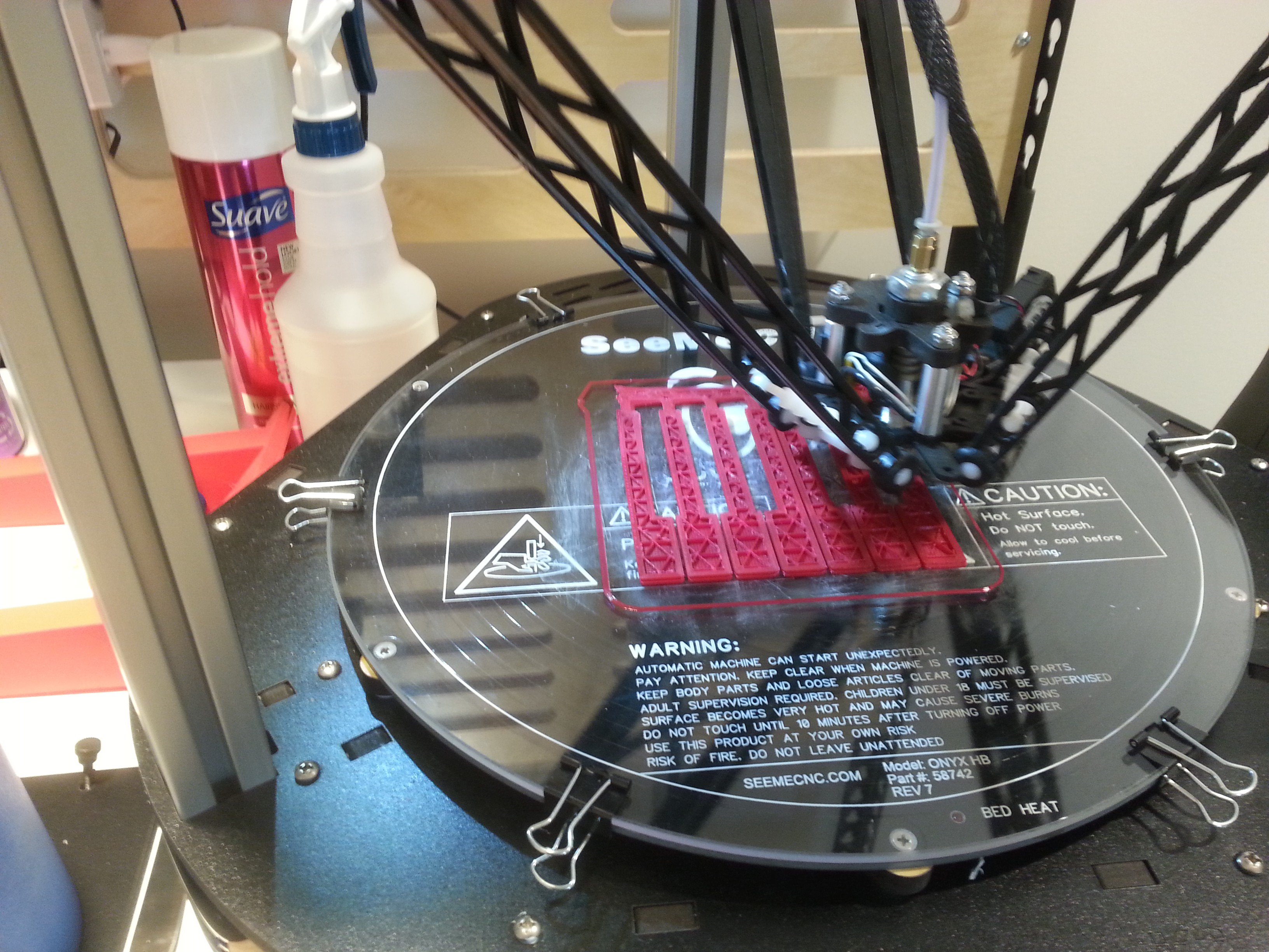
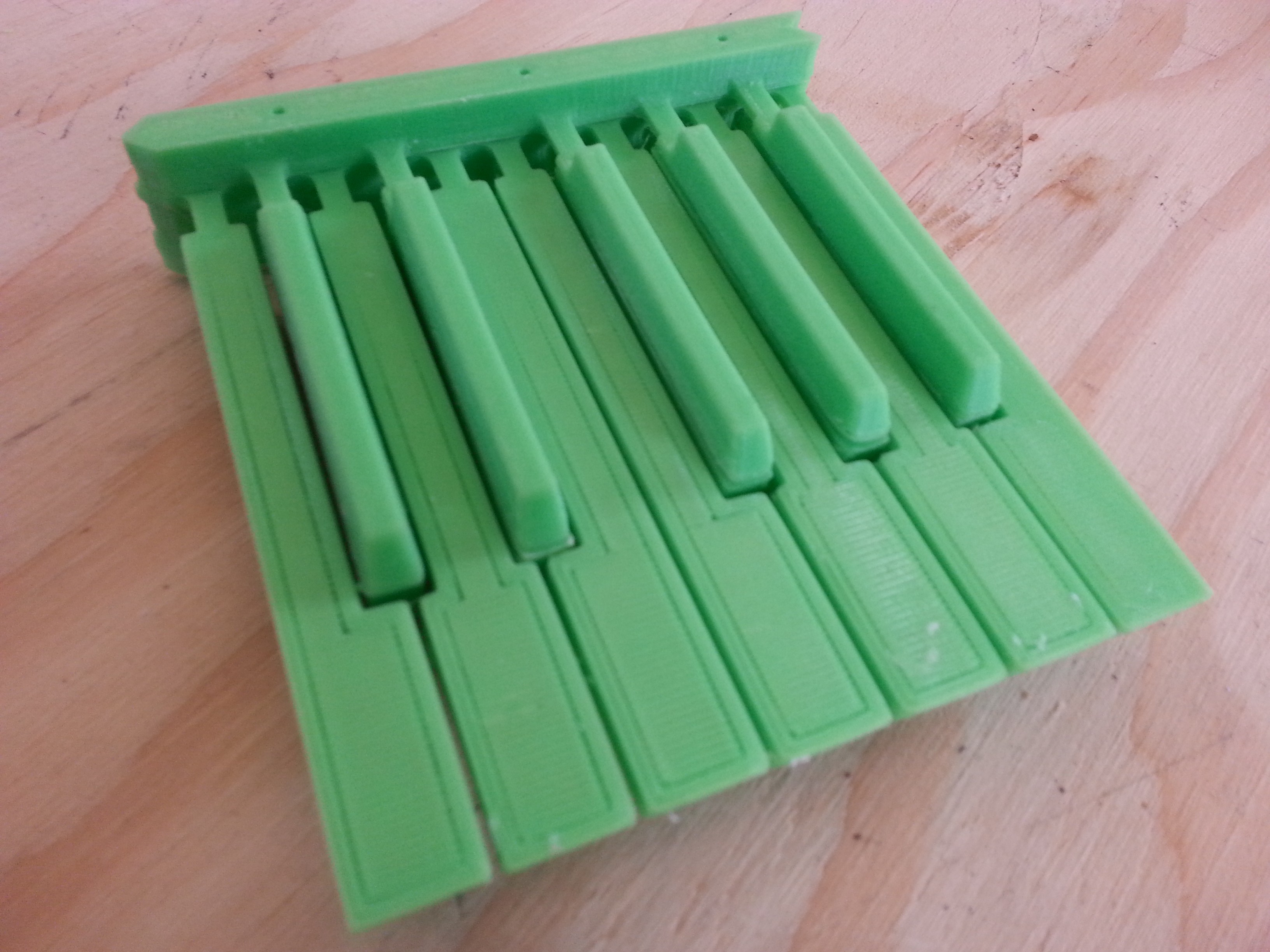
08/11/2016 at 01:57 • 0 commentsSo, I made a test print of the new keyboard model I made in Autodesk Fusion 360 the other day. In case you didn't read the last post, it looked kinda like this:
![]()
It took a few tries to get a reasonable 3d model out of the Rostock printers. It didn't like some text I had placed on the bottom of a few small parts, and I had set the resolution fairly high, so the extruder would sometimes clip the model and move bits around. 3d printing kinda sucks.
But after a couple of tries I had to leave the office, so I just let it go, and it came up with passable prints in the morning!
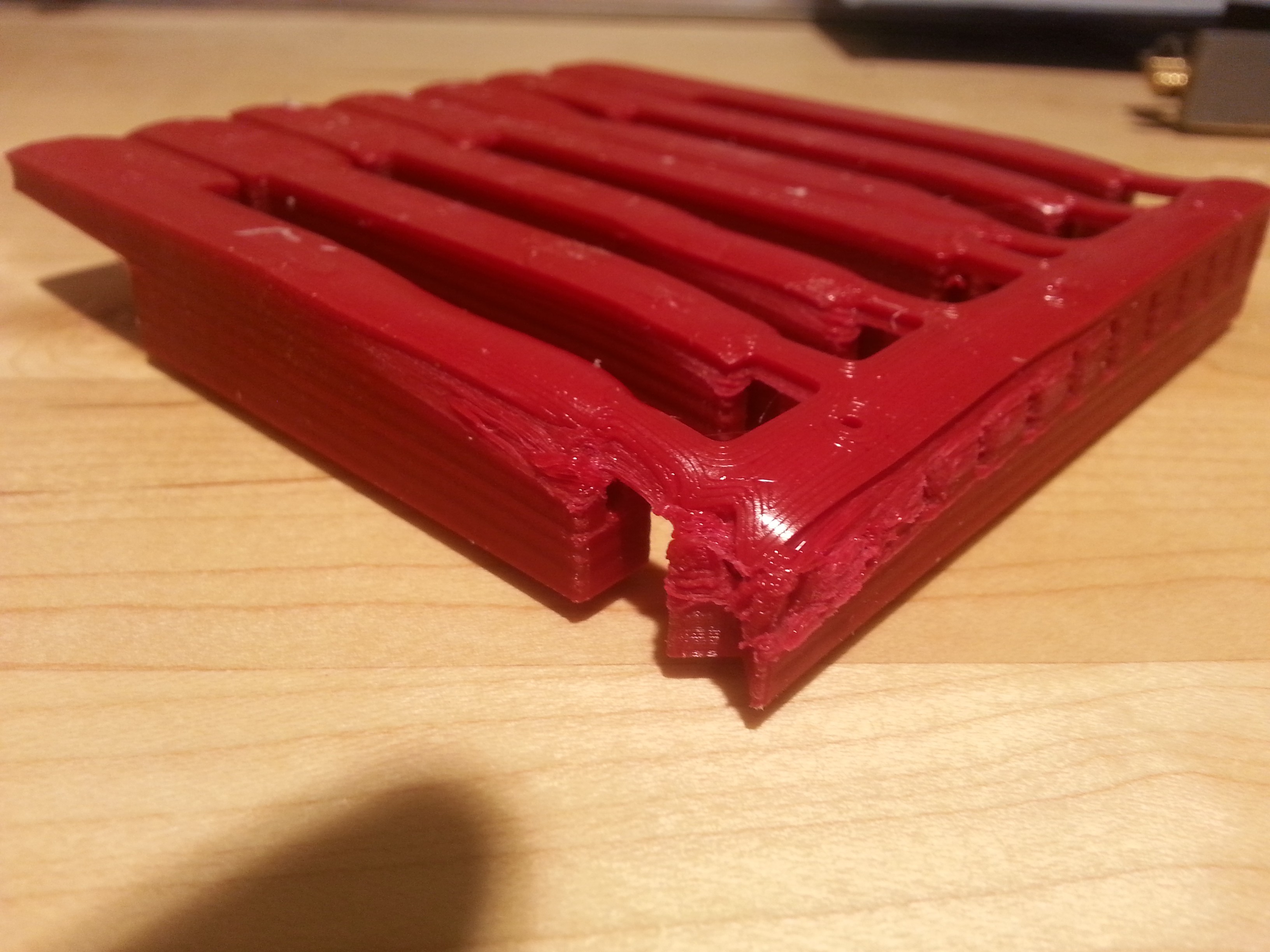
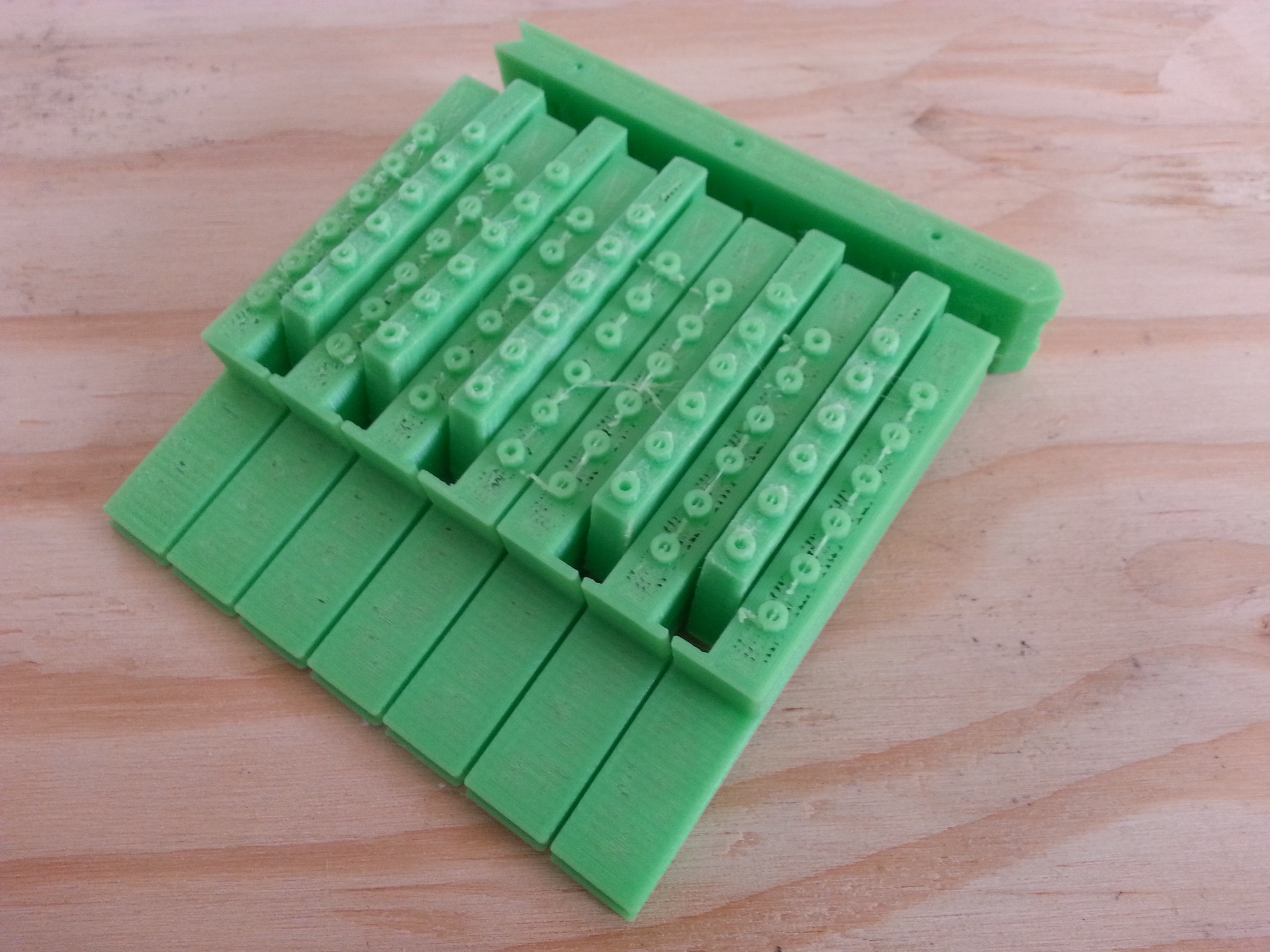
There were some strange artifacts, tho.
Some sort of "ghost wind"?
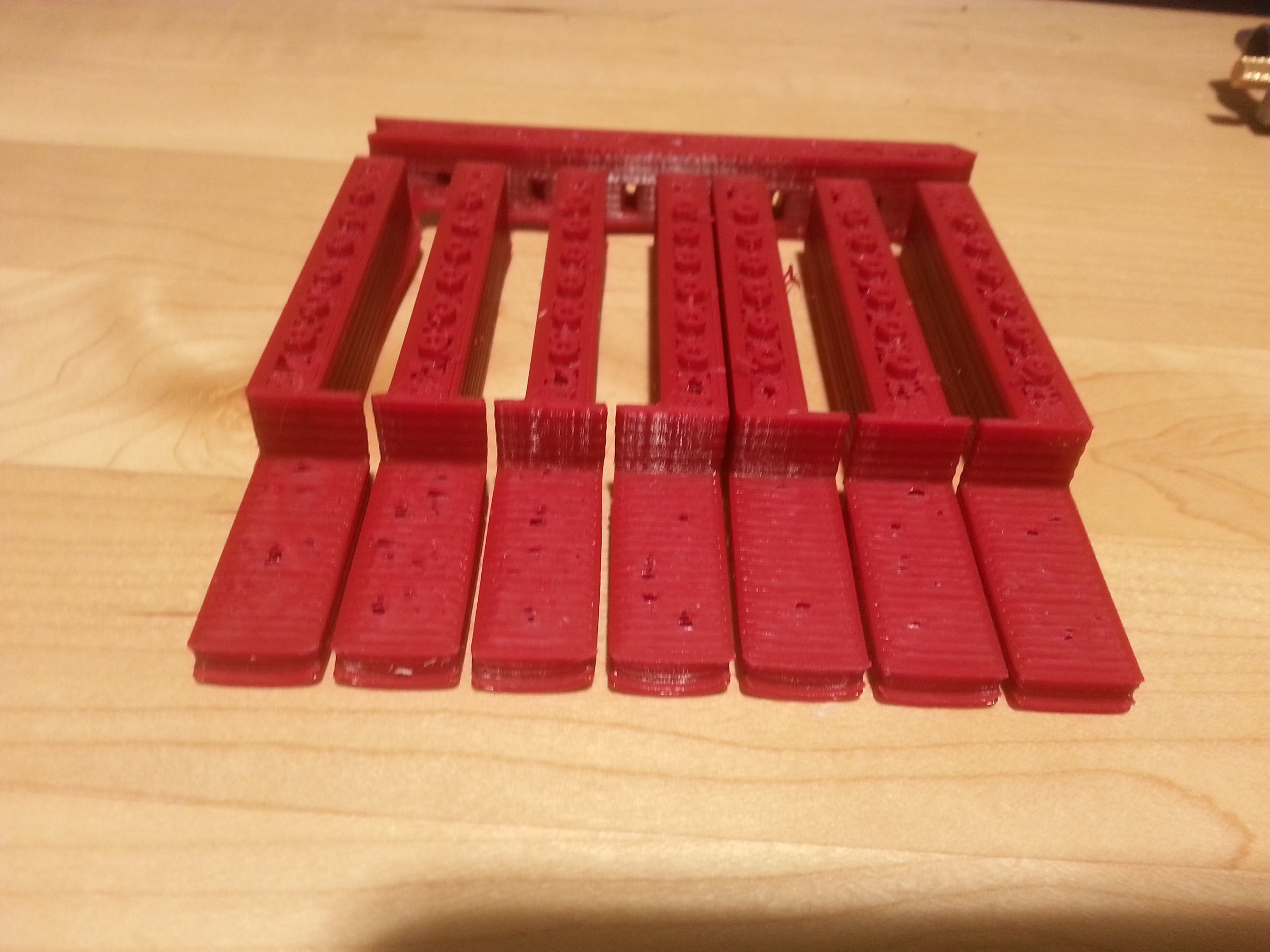
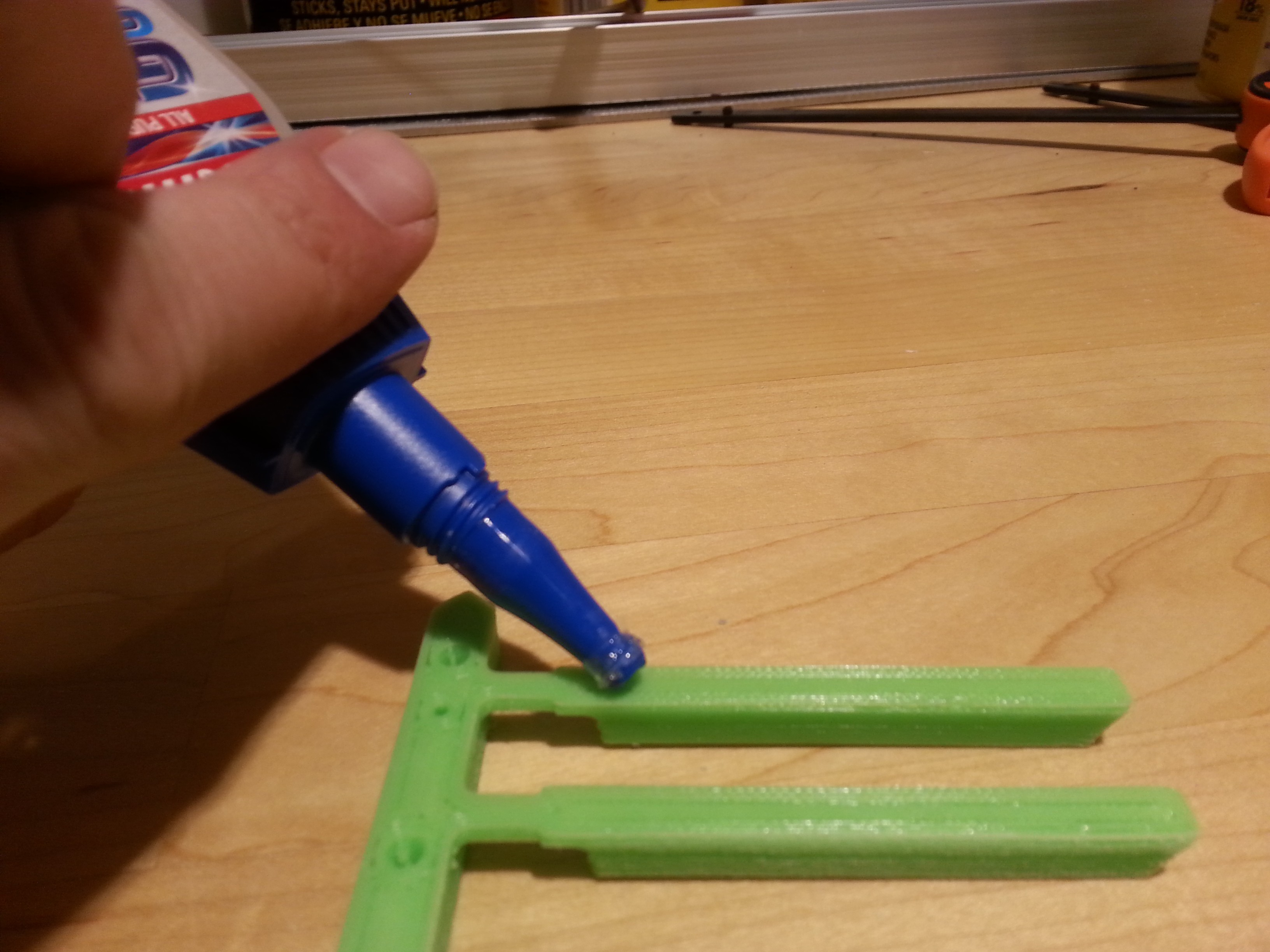
As always, I made separate models for white keys and black keys. The black keys had to be split into two parts because there needs to be a flat surface somewhere for 3d printing, so there is a top and bottom for each black key. I also added some parts to act as "cookies" or joiners to hold the two halves together. I had hoped for a friction fit, but it did not quite turn out that way, so I had to glue them.
The white keys could be printed as a single solid.
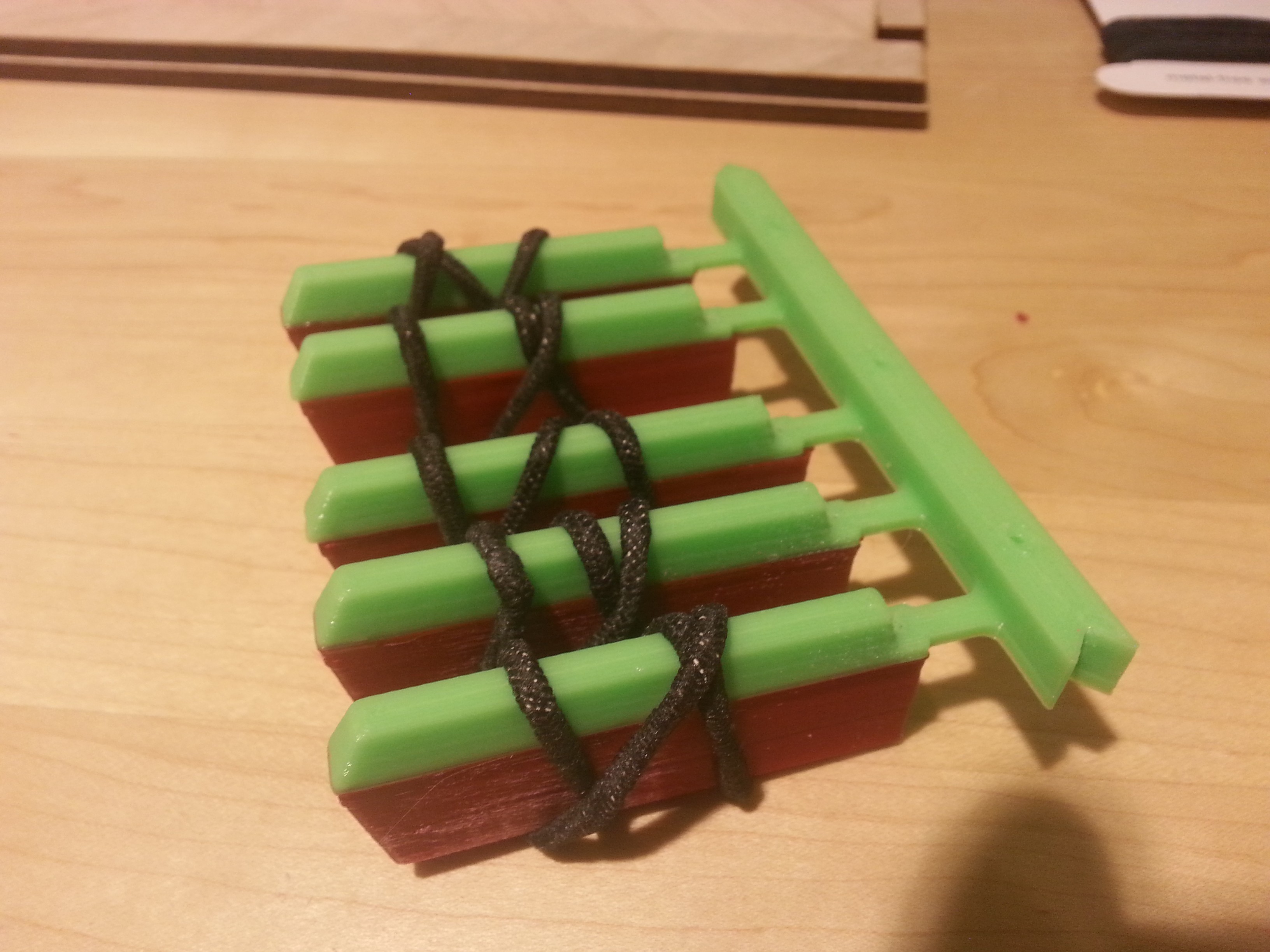
I added some cookies to hold the black and white key sections together too.
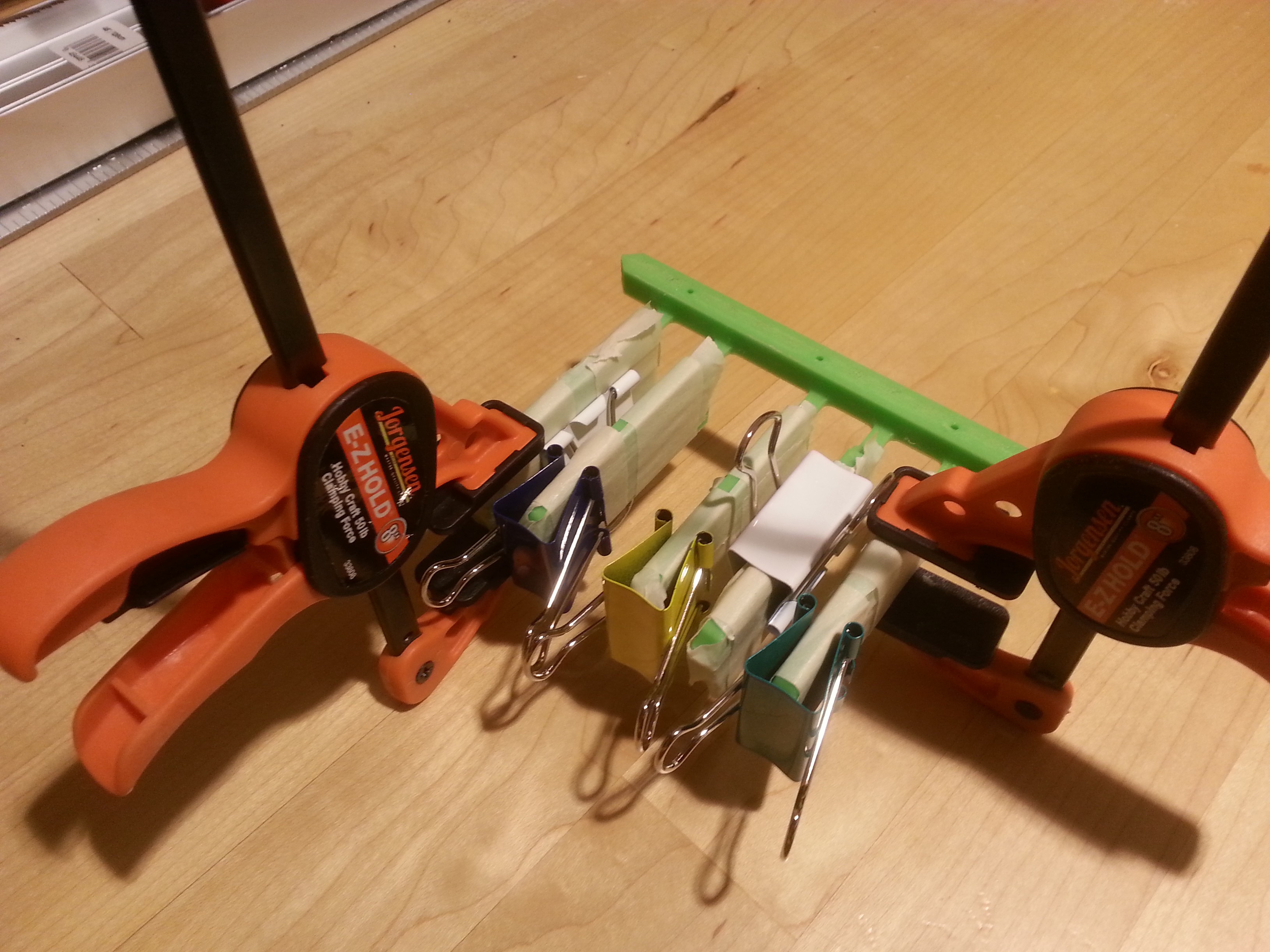
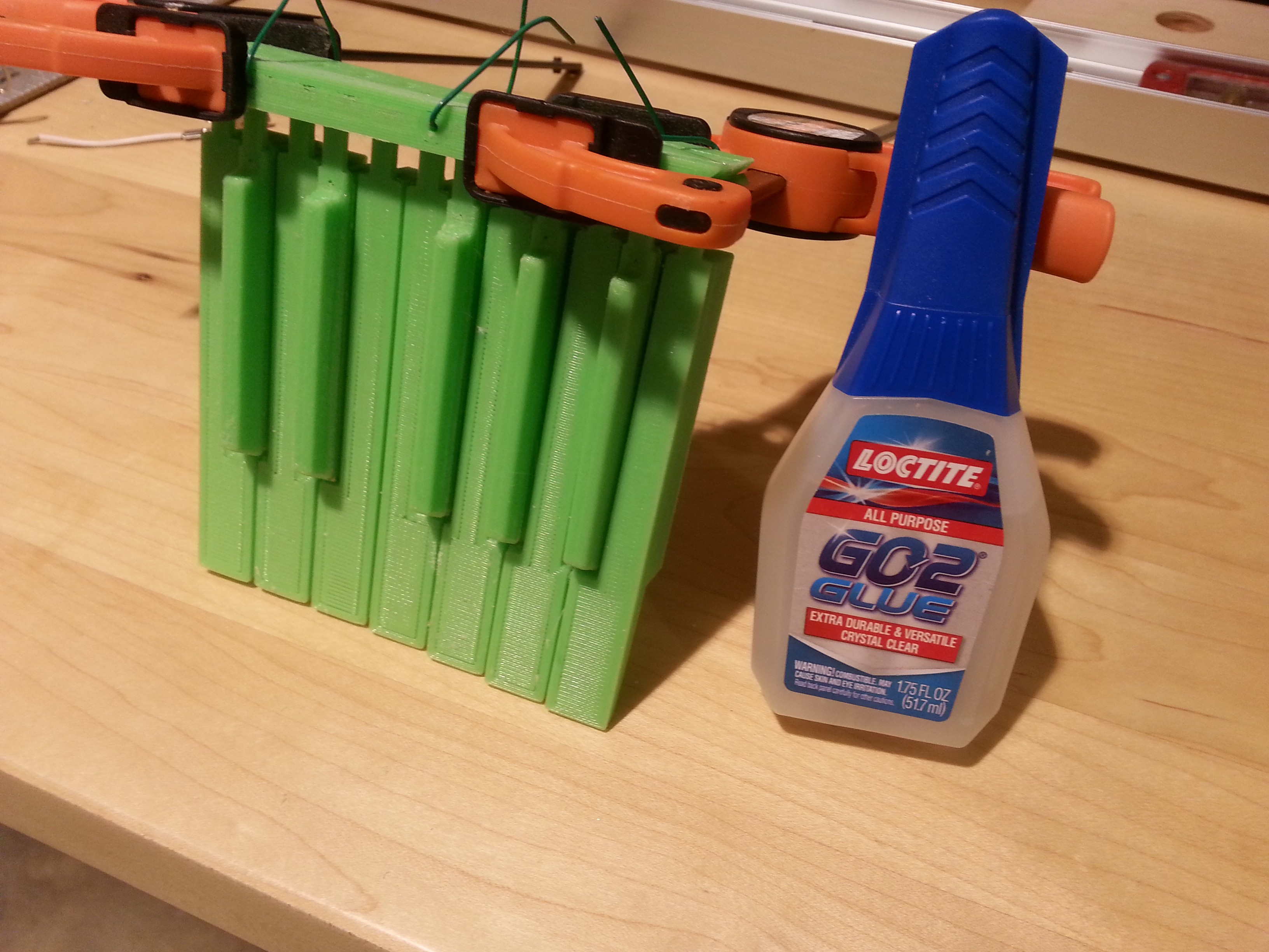
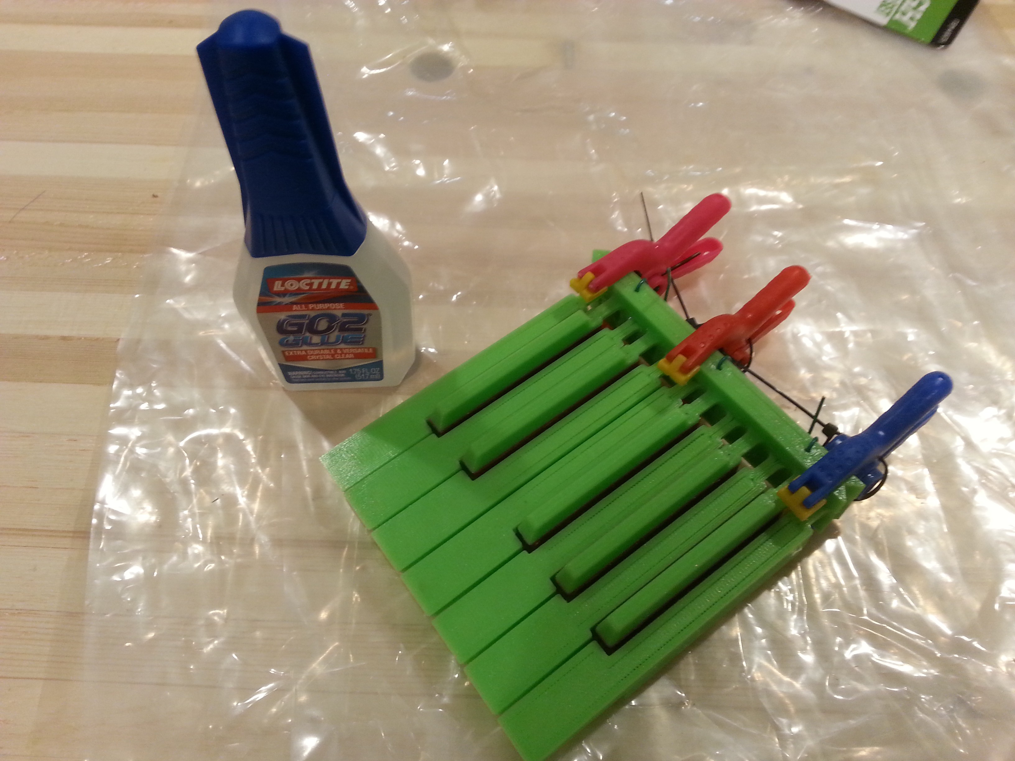
And I wrapped the whole thing in rubber bands to keep tension while the glue dried.
Already, I've found a number of things to fix, so chances are this print won't actually end up in a prototype, but it does help to check the scale of things.
Speaking of which., I was tired of having so much trouble with not having a good throw on the keys, I decided to disassemble a stack of toy keyboards and take down some metrics. Hopefully this helps me make something that it actually playable.
More to come!
-
Starting over: New Keyboard Model
08/09/2016 at 00:47 • 0 comments![]()
I'm going to jump ahead a bit. The previous logs are for things I did weeks ago, but haven't had time to document yet. I'll get back to those, but I wanted to start sharing current events.
My 3d software suddenly stopped working, and nothing I could do was able to bring it back. After a few days of hammering on the PC trying to find the problem, I gave up. All of my work on the case, keyboard, knobs, etc. was tied up in that software, and without it, I can't really do much except keep printing the old models.
So, I have started over using the Autodesk Fusion 360 software. It seems to be free for companies making less than $100k a year, which means I'm probably 10x overqualified at current earnings. I looked at other software like OnShape (not quite mature, too limiting in the free version), Blender (completely incomprehensible UI, not parametric), Freecad (rage quit before I could determine how to do anything with it), Wings (not really suitable for this kind of work), Sketchup (doesn't make solid bodies, not parametric), and Fusion 360 seemed like the most mature solution that I could afford. The UI wasn't completely alien, and it *is* a parametric modeling program.
Granted, I don't actually know how to use the Fusion 360 software, and certainly it is not a 1:1 feature comparison with my old software, but I don't have a lot of choice in the matter but to dive right in.
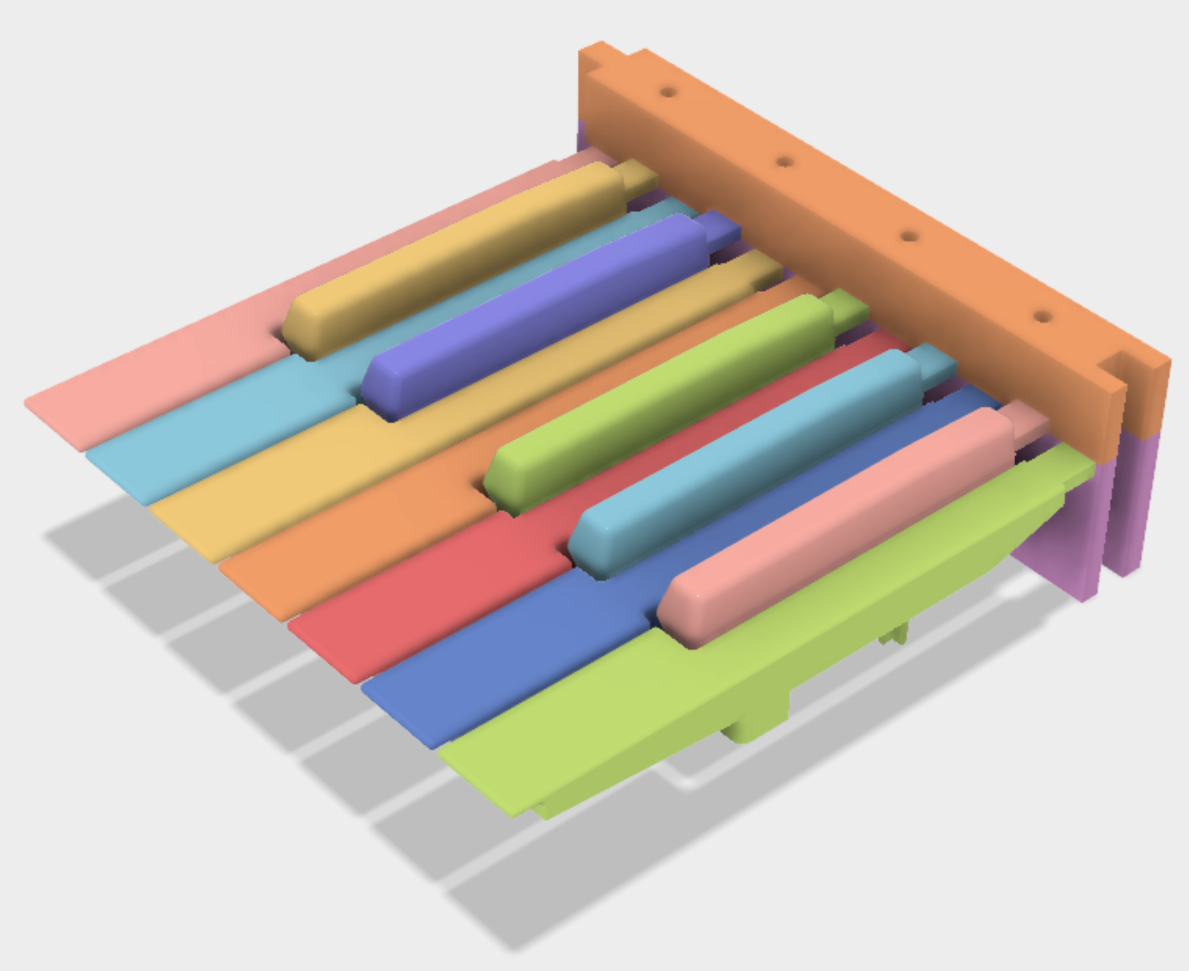
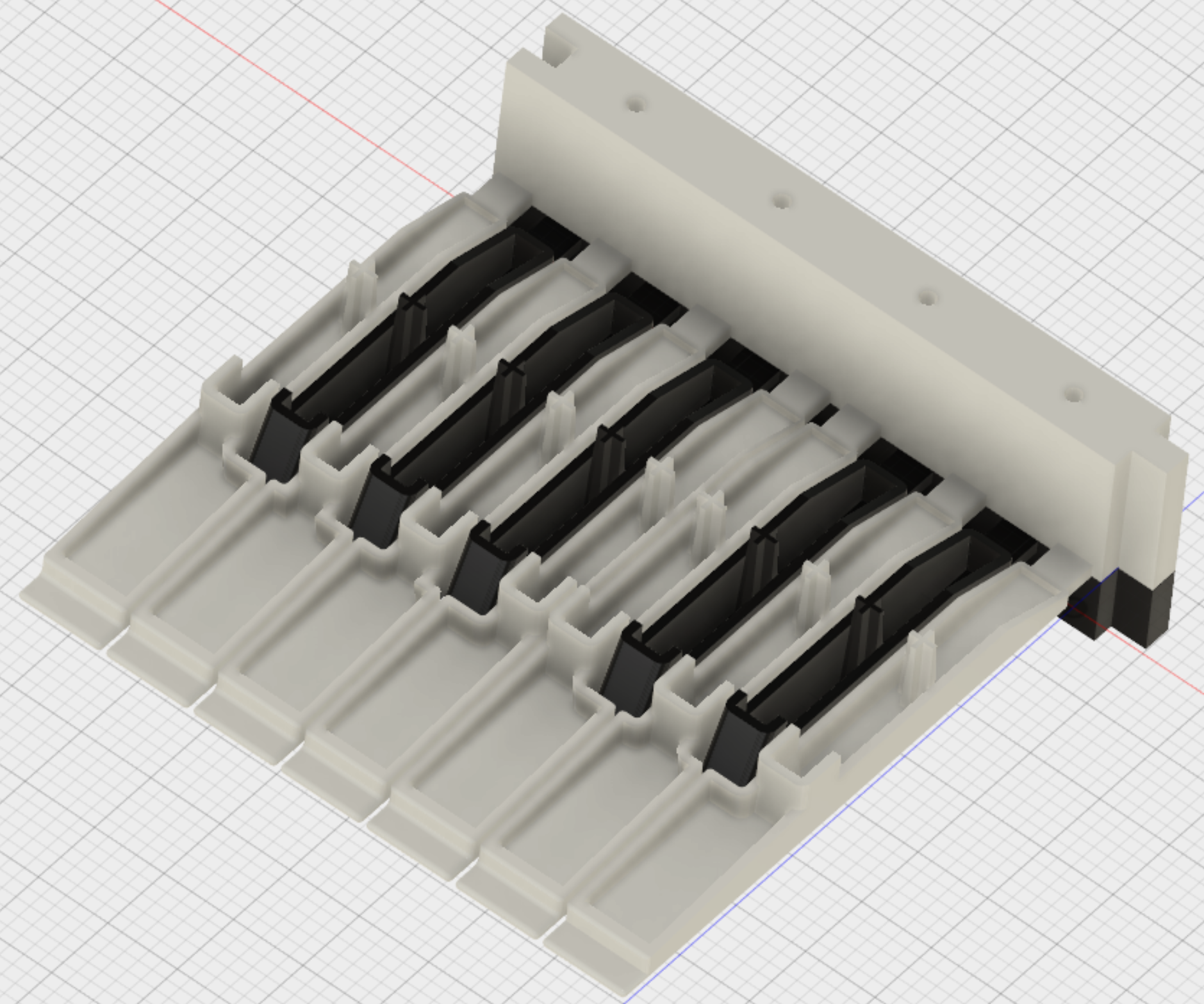
After two days of work, I've managed to create a new model of the keyboard mechanism, by far the most complicated part of the project. Hopefully everything else will be easy now that this is done.
This design was done with an eye towards injection molding rather than 3d printing, hence the hollow keys. The back mounting block will probably have to be changed for the final tho.
I changed to have just one set of nubs for the pressing on the rubber contact pad switches. I am a bit worried that they might be too long and move too much forward and back when the key is depressed. I should probably try to do some simulation on that, but I'm just now determining how to use the software... haven't gotten that far yet.![]()
The mounting block is currently much taller to eliminate wooden shims I had to use on the old keyboard. Also there is a notch on the end of the mounting block that allows for a more accurate fit, hopefully preventing the snaggle-tooth between the octaves I currently get.
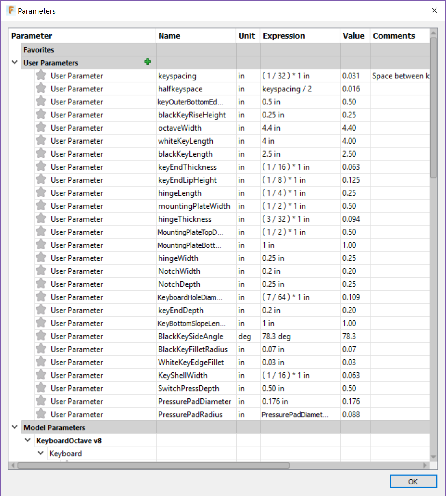
One great advantage of this software is that you can use variables to specify the parameters of your model, and then change them and it will automatically update your model to match. The old software had this, but it didn't work at all.
![]()
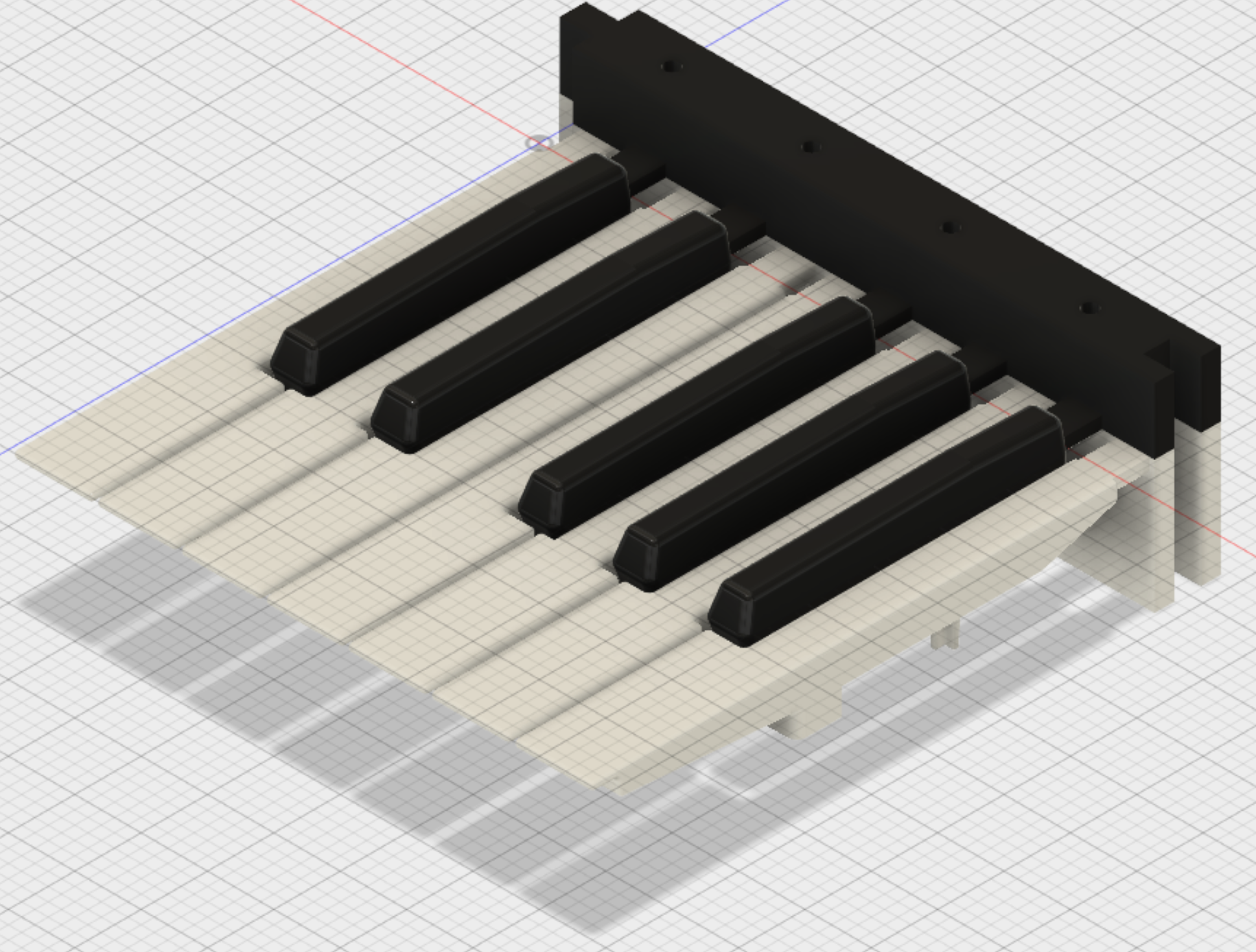
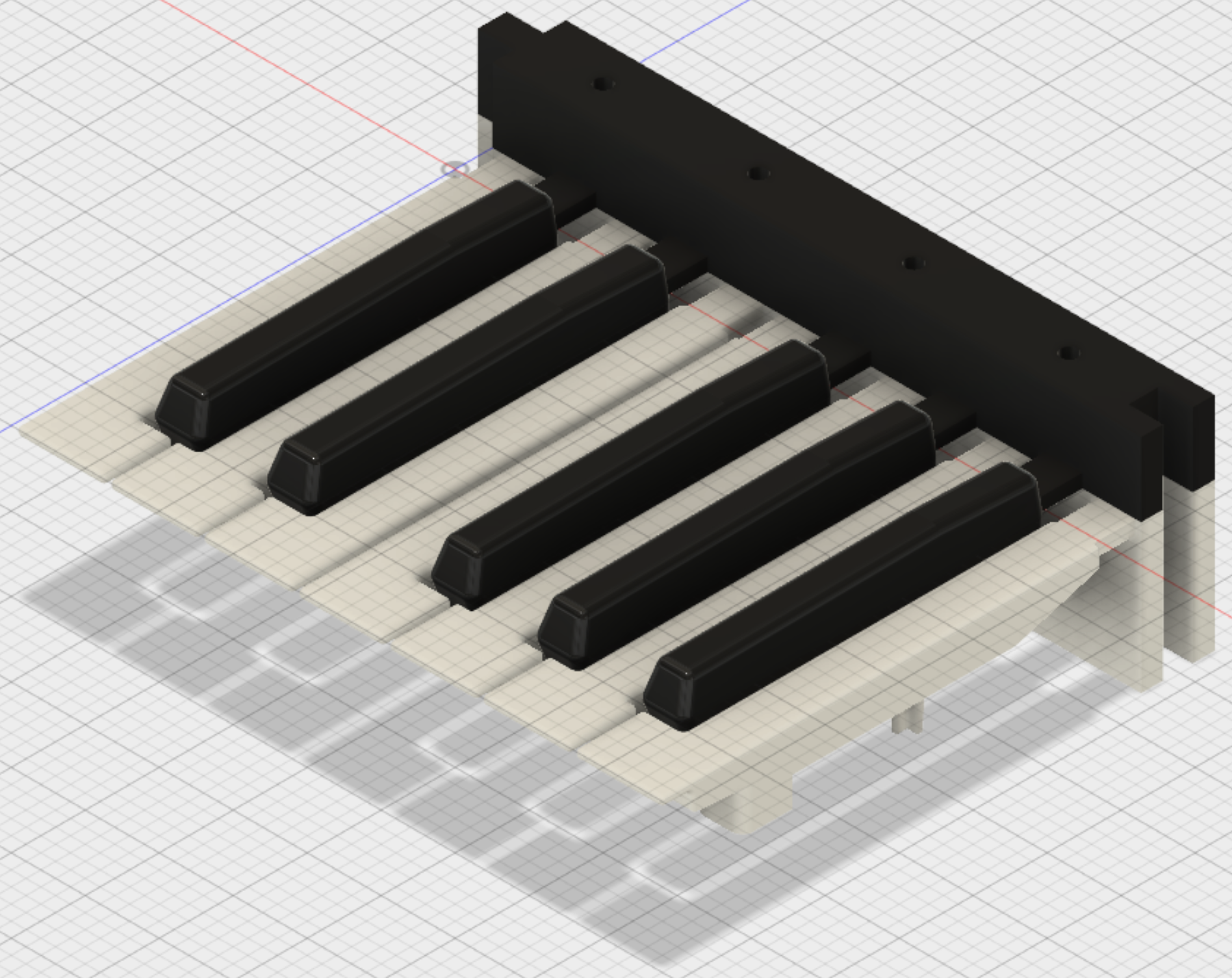
For example, here I adjusted the white key length to be absurdly short... the model recalculated correctly!
![]()
I'm sure this will require some iteration, but this is the hardest part of the box to model, so hopefully I can have a complete redesign ready to go sometime this week.
-
Keyboard Circuits
07/29/2016 at 23:09 • 0 commentsNow that we have these wonderful 3d printed keyboard sections, and have mounted them in the case, we really need some way to electronically tell if a key has been pressed.
The plan is to develop a printed circuit board with traces that act as contacts, and use those graphite impregnated silicone rubber cups to bridge the contacts and tell if the key has been pressed. I've disassembled a lot of toy keyboards, and that is how it is generally done.
Since we have the Othermill here at the Supplyframe Design Lab, it seems obvious to make the board here rather than to send out for it and wait a week. So I designed the circuit board in KiCAD, a program I wasn't really too familiar with yet.
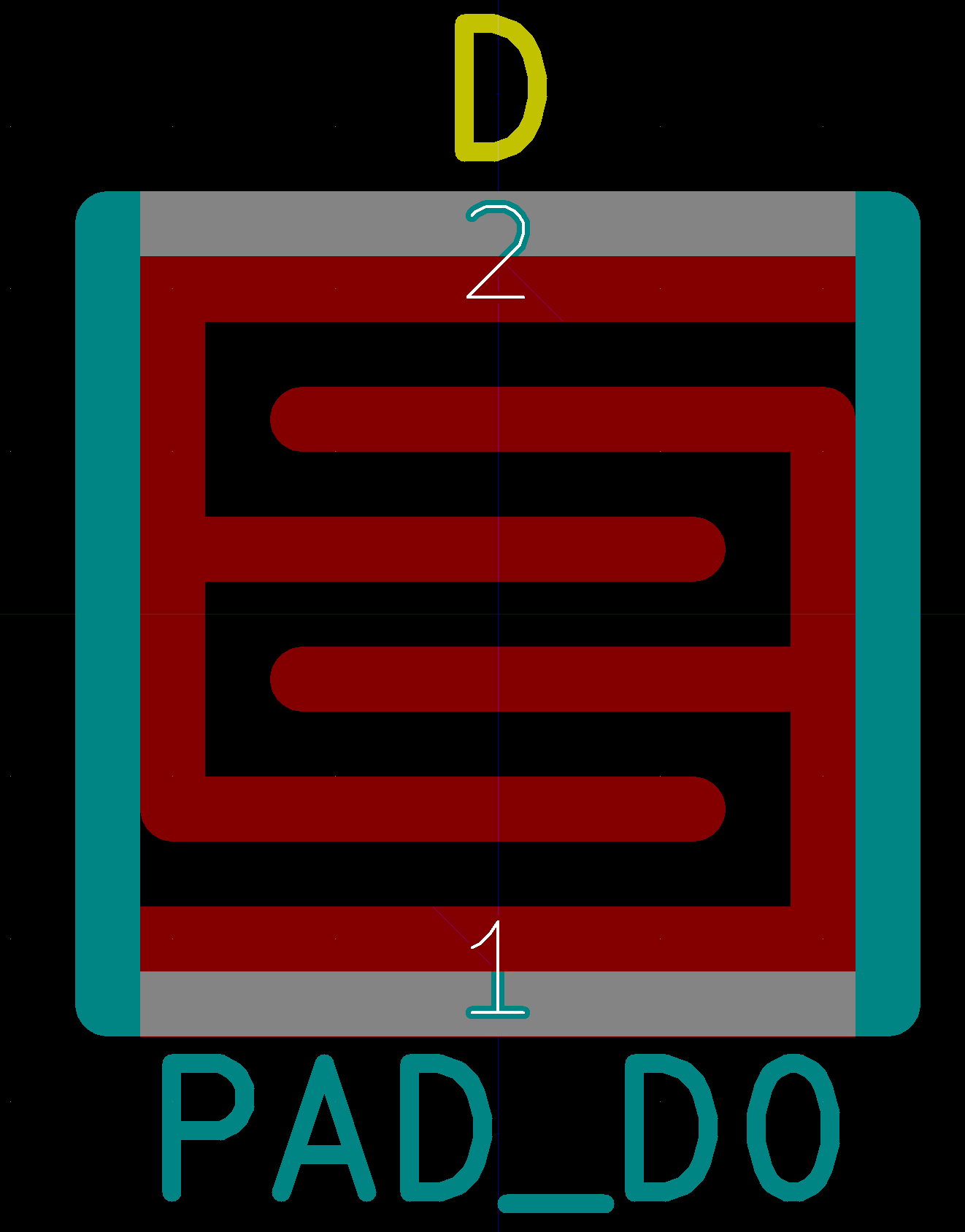
In order to make the contacts on the PCB, I had to lay out copper traces on the PCB so that the rubber pads could bridge them easily. To do this, I made a custom footprint, as if I was going to mount a switch on the board, but I didn't put any holes for pins, just the pattern for the contact. This was a bit tricky, because KiCAD won't let you draw on the copper layer in a component except by placing a surface mount pad. Well, I thought that was kinda dumb, so I drew it on another layer and edited the text file to change it to the copper layer.
So, the first switch pad I designed looked like this:
![]()
Looks nice enough, but there are barely 10 mils of spacing between the traces. While the Othermill can theoretically handle this, we had some trouble with it.
The 30 degree end mill that we used was supposed to be good for this, but somehow it didn't work out; all the traces vanished! So I adjusted the footprint for a wider spacing.
![]()
These have 20 mil traces and 20 mils between the traces, surely that will be good, right?
So we mill out another test. This seems better, right?
Still doesn't quite match what we drew, but maybe give it a go?
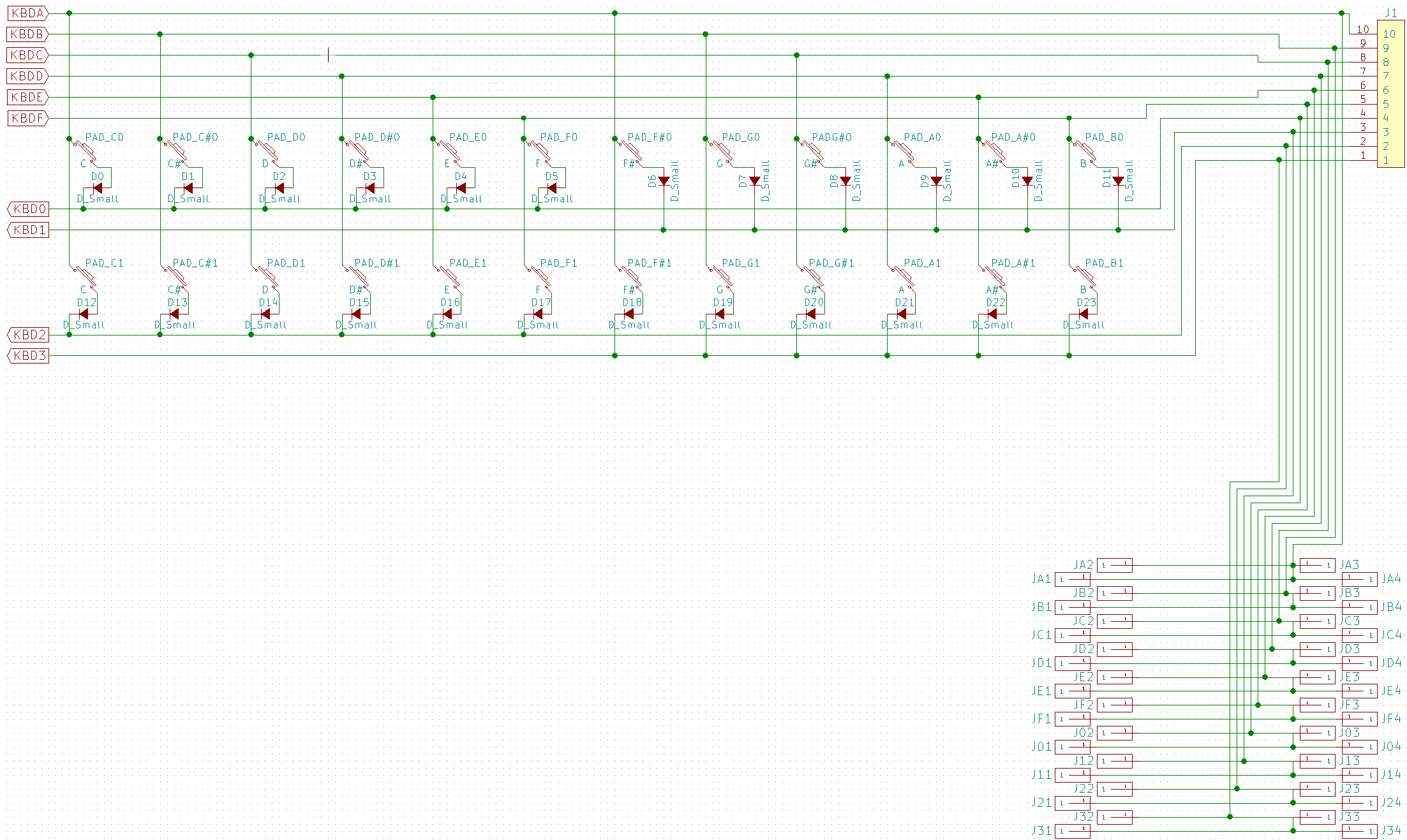
A schematic was made:
![]()
Diodes on each switch to prevent current from rushing up the wrong way and causing false triggers when chords are held.
The PCB had to be split into two parts because the Othermill will only do a 4" x 5" board.
Here is the front.
And the back:
The 2nd board was missing part of a trace for some reason, so some rework was done:
And the boards were joined together with 0 ohm surface mount resistors:
As you can see, when the Othermill routs a circuit board, it doesn't rout all of the extra copper away, just the area around the trace. If you mill the board with a small bit, the area around the trace will be very thin, as it is here. This makes it VERY HARD to solder without bridging a connection! It took me a very long time to solder one of the vias (which are not plated through, because the Othermill has no way to do that) and I got more solder around the via than on it.
So shop head Dan had a go at it.
In half an hour, we got maybe 6 of the 36 vias soldered, at which point I said "This isn't worth it, I'm going to redesign the board. It will be faster."
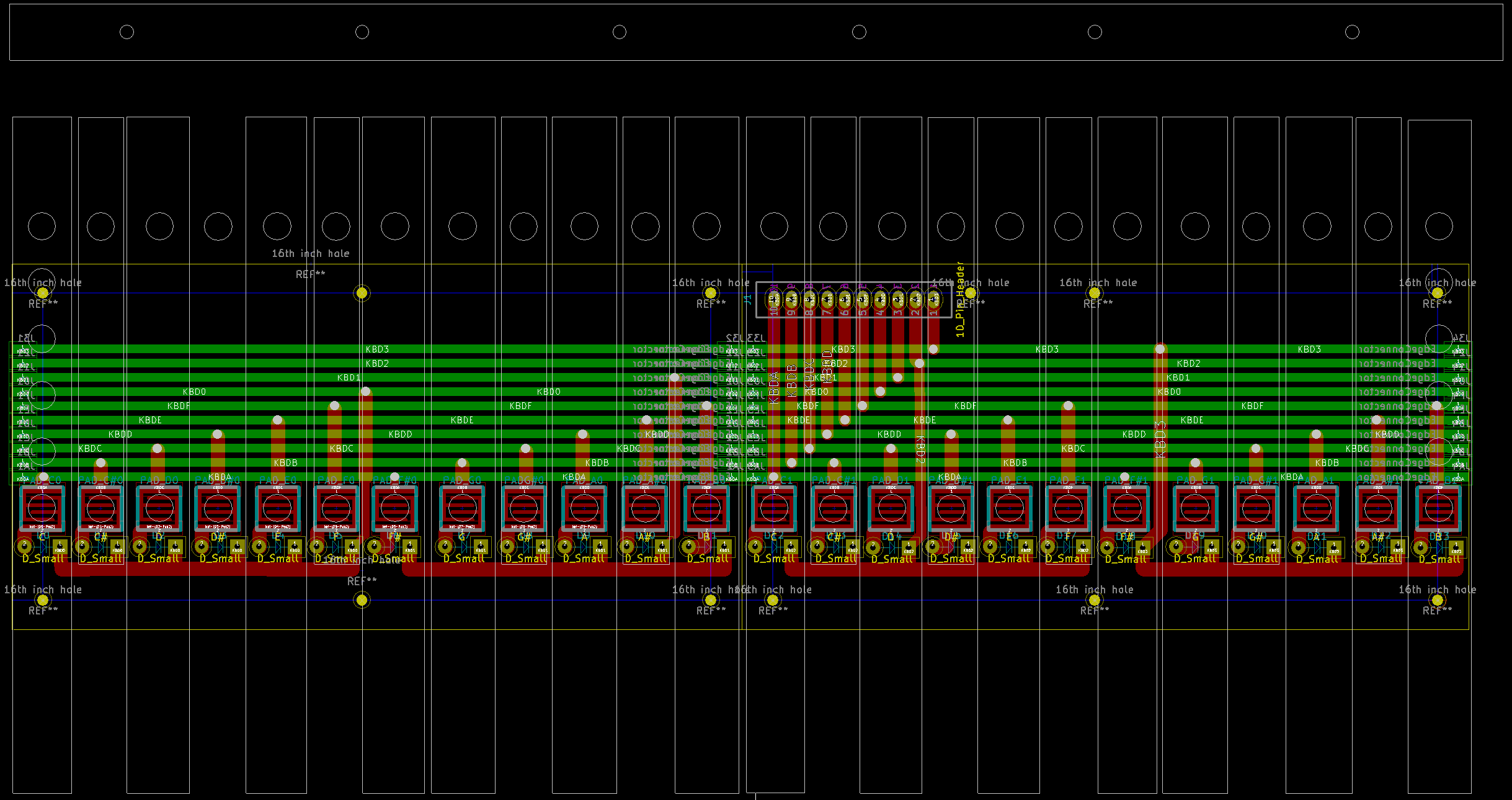
![]() Here is the new board. Note that I imported a DXF of the key spacing to know how to line up the switch contact pads. The traces are a good 60 mils in most cases, and the vias and pads have large enough holes to work easily with a 1/32" flat end mill.
Here is the new board. Note that I imported a DXF of the key spacing to know how to line up the switch contact pads. The traces are a good 60 mils in most cases, and the vias and pads have large enough holes to work easily with a 1/32" flat end mill.
Meanwhile, Dan experimented with the Othermill and came up with a prescription that works:
We were also having some troubles with our mills not being quite up to spec, so when we did the 2nd PCB the next day it came out MUCH better! The board on the left is the earlier board, and the one on th eright is the later one.
Although the one on the left has nice large gaps around the traces, the switch contact pads have VERY thin traces. The board on the right is a much better balance and matches the design more exactly.
The back of the board shows this as well.
Rather than waste a bunch of 0 ohm surface mount parts, I just bridged the connection between the boards with some solder.
Here is the fully populated board!
Note that I still got some solder on the copper away from the via, but it wasn't in danger of bridging the connection, at least.
Next up is to get some rubber contacts for the board and see if they work. I started to plan a way to fabricate a mold, but Dan suggested that was a waste of my time, so I sacrificed one of my keyboards to get some.
The spacing wasn't the same, so I cut them up with scissors.
For the first test, I tried to tape them down with some gaffer's tape, but since nothing really sticks to silicone, it didn't work very well.
I tried using Silly Putty as an adhesive. While it does a great job of sticking to silicone, it is not goot at sticking to anything else.
So, I decided that a mechanical solution was best. I designed an acrylic jig to hold the silicone switch pads in place. I cut this out on the laser cutter.
And ended up with this:
Unfortunately, there were some issues in scaling, and this part is completely wrong.
So, back to the cutter...
And we're done! Let's try it!
Here it is, in all it's glory!
Of course, the screws were too long, so I had to trim those down to size. Here is the screw cutting montage! <cue rocky music>
Of course, this left the ends horribly burr'd, which made them much harder to put nuts on after. Cue the little wrench!
At this point, deficiencies in the design really started to show. The screws holding the acrylic that holds the pads in place, and even some of the acrylic itself, is blocking proper operation of the keyboard. So I cut some of the nubs off the bottom of the keys.
The nubs also don't *quite* line up with the rubber switch pads, but I only have the one set of keyboards printed, so I am determined to make it work. I need to measure precisely the position of each as it was glued. Doing that with a caliper would be fraught with error, so instead I just put it on the scanner and then traced it in Illustrator, making a DXF that could be imported into all of the CAD programs to make a new pad holder on the laser cutter.
Stay tuned for part 2: The revenge of the keyboard!
-
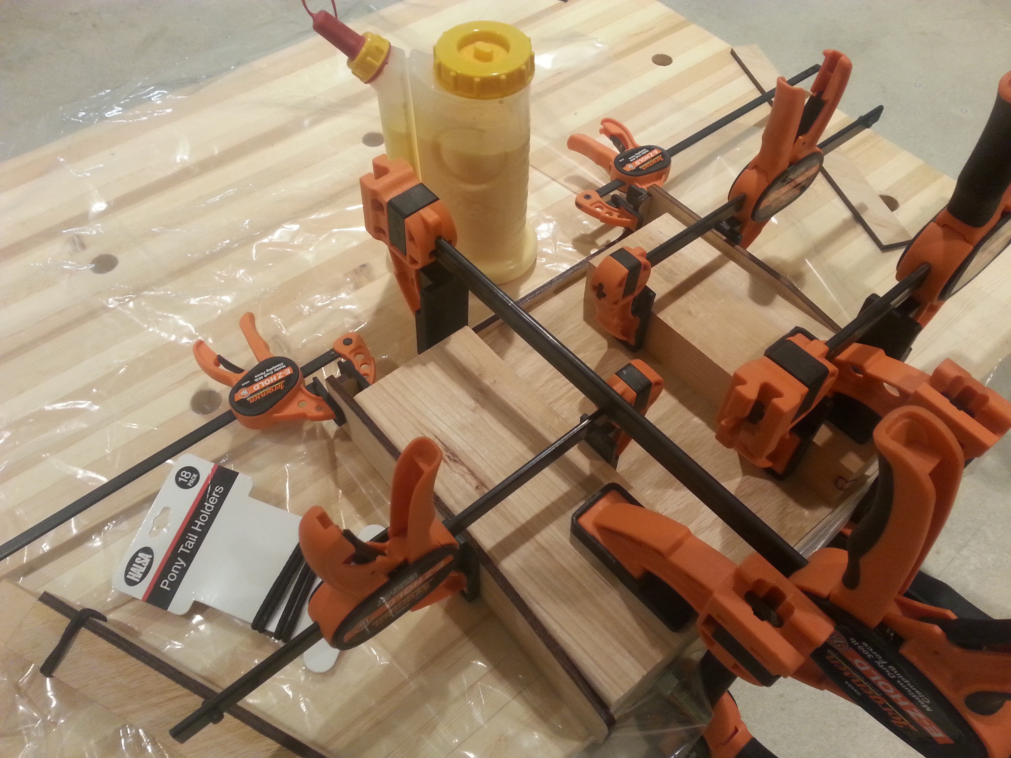
First prototype box!
07/29/2016 at 06:18 • 0 commentsWhen I last left off, I had just started gluing the first draft box together after laser cutting all of the pieces out. Here is the control rotopod sitting in the clamps.
Because we had some trouble printing the keyboards, we couldn't put it all together right away, so we did some test fitting.
Lookin' good!
Eventually, the other half of the keyboard finished printing, and I was able to glue that together. I found some tiny clamps that were perfect for holding it together while the glue dried! No more hairbands and giant bench clamps!
While the glue was drying, we did another test fitting.
Nice! This is really shaping up! That top cross bar is glued in, BTW, which I later decided was a bad idea. In hindsight, I think that perhaps that was supposed to sit on top of the side edges, not between them. I think I had some length problems when I tried to convert the 3d model to a 2d drawing for laser cutting, and I ended up having to sand a lot of parts to fit. Perhaps this was one I should have left alone...
Now, the design had lots of round corners and such, which were originally supposed to be cut on a ShopBot CNC router with 3d control of the cutting head, but since that wasn't available, we did it on the laser cutter. So there were lots of edges that were supposed to have been delivered rounded that were instead square. Since the lab's sander was not yet available, I took the whole thing over to MAG Laboratory in Pomona and used their lovely sander for hours until everything was super round.
Now, the rotopod is supposed to have a touch screen and a huge ton of knobs on it, which necessitates a fancy, shiny face plate. I decided to cut that out of acrylic. MAG Lab's laser cutter came in handy here.
Now, you might notice that the screw mounting holes at the edges are so close that they have merged with the edge. This is because the wood being used is not quite the 1/4" I spec'd, and so the holes have to be in kind of a precise place. Not the best. Also, the holes in the corners don't work so well after you have just sanded off the corners! So I just broke them off... they were kind of pre-broken off, anyway.
So, now I've got most of the pieces, let's do another test fitting!
Wow! That is really starting to look the part! It's so pretty, let's see that again!
Now, in these photos, the keyboard is kinda balanced on some blocks of wood. We can't really get an idea of how it is going to play until we actually mount it so that the keys don't rest on the front of the keybed. So I carefully drilled some holes and used screws to put it together.
Success!
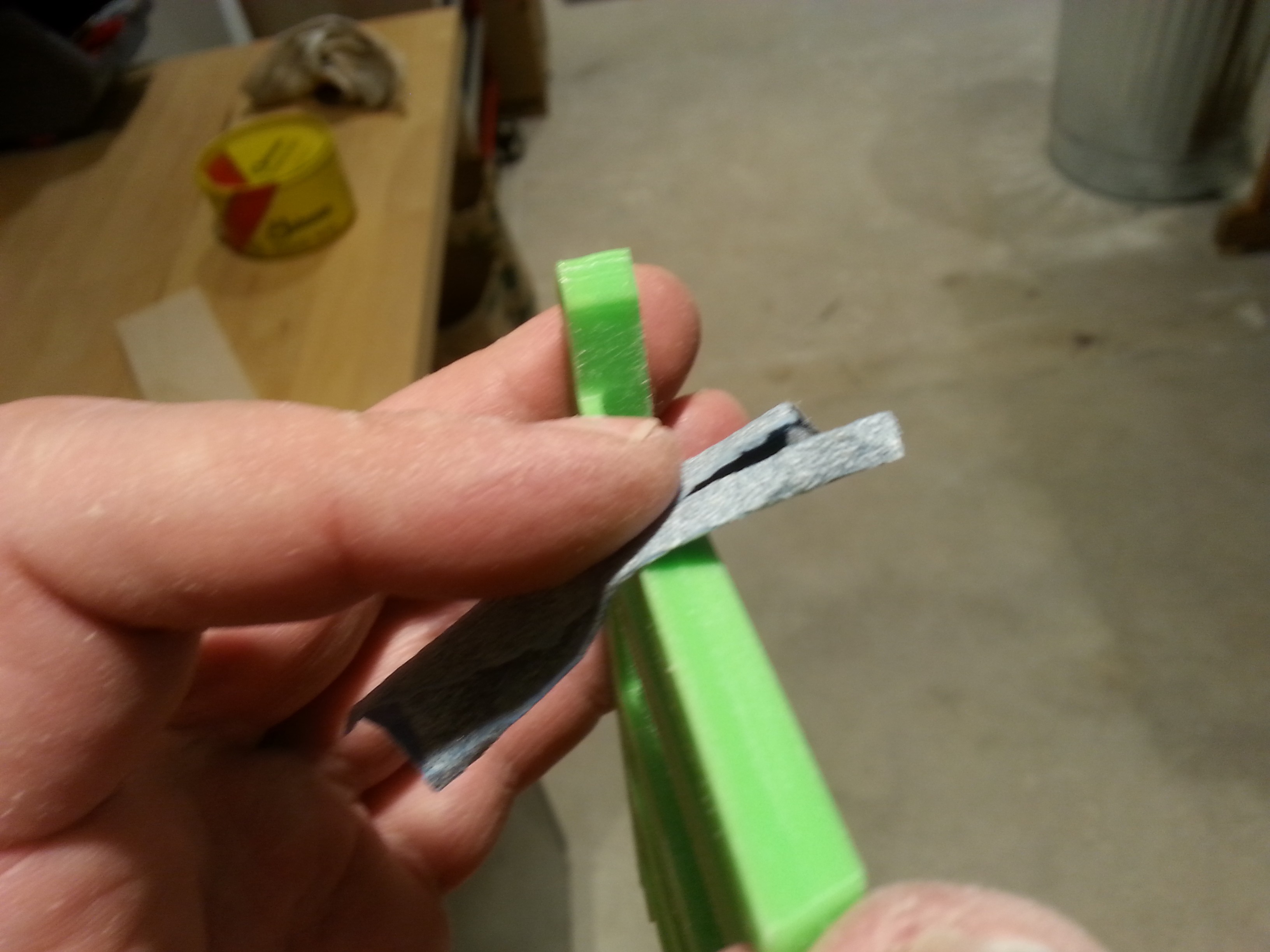
It works! And using the thin plastic strip as a spring works as well as I had hoped! Oh, joyous day!
Next, I need to mount the rotopod to the back of the keyboard. I mentioned to Trent at MAG Lab that I needed a piano hinge, and he just gave me one! It was super long!
I ran into Machinist from 23b Shop while I was at MAG Lab. Since the band saw at MAG Lab was down, he let me go cut it on their machine!
So I took it down to 23b Shop in Fullerton and cut it with their cutoff saw! (Sorry for waking you up Bobby!)
Having a proper sized hinge in hand, I then had to drill some mounting holes.
And screw it together with the handy screws that came with it.
I carefully marked where on the hinge the edge of the keyboard should be so that it will be lined up correctly when I have to flip it over to put the screws in.
Carefully, screw it together, making sure the alignment is still correct.
Attach one of my touch screens to the back of the front panel.
Do a test fitting.
The rotopod even rotates, although the fit is kinda tight...
And here it is with some of the test printed knobs on it.
I still need the pitch and modulation wheel assembly on the left, so I printed that...
Note that there isn't really a good way to get the potentiometers into these. This is just a test print.
It didn't really fit because of the wood that I had added to the keybed to would block it from sitting down correctly. I I took a hackaday saw to it and made it fit!
So here is everything assembled.
So. there it is! The entire prototype case! Now I just have to make the circuits to fill it up! -
First draft case: Laser cut
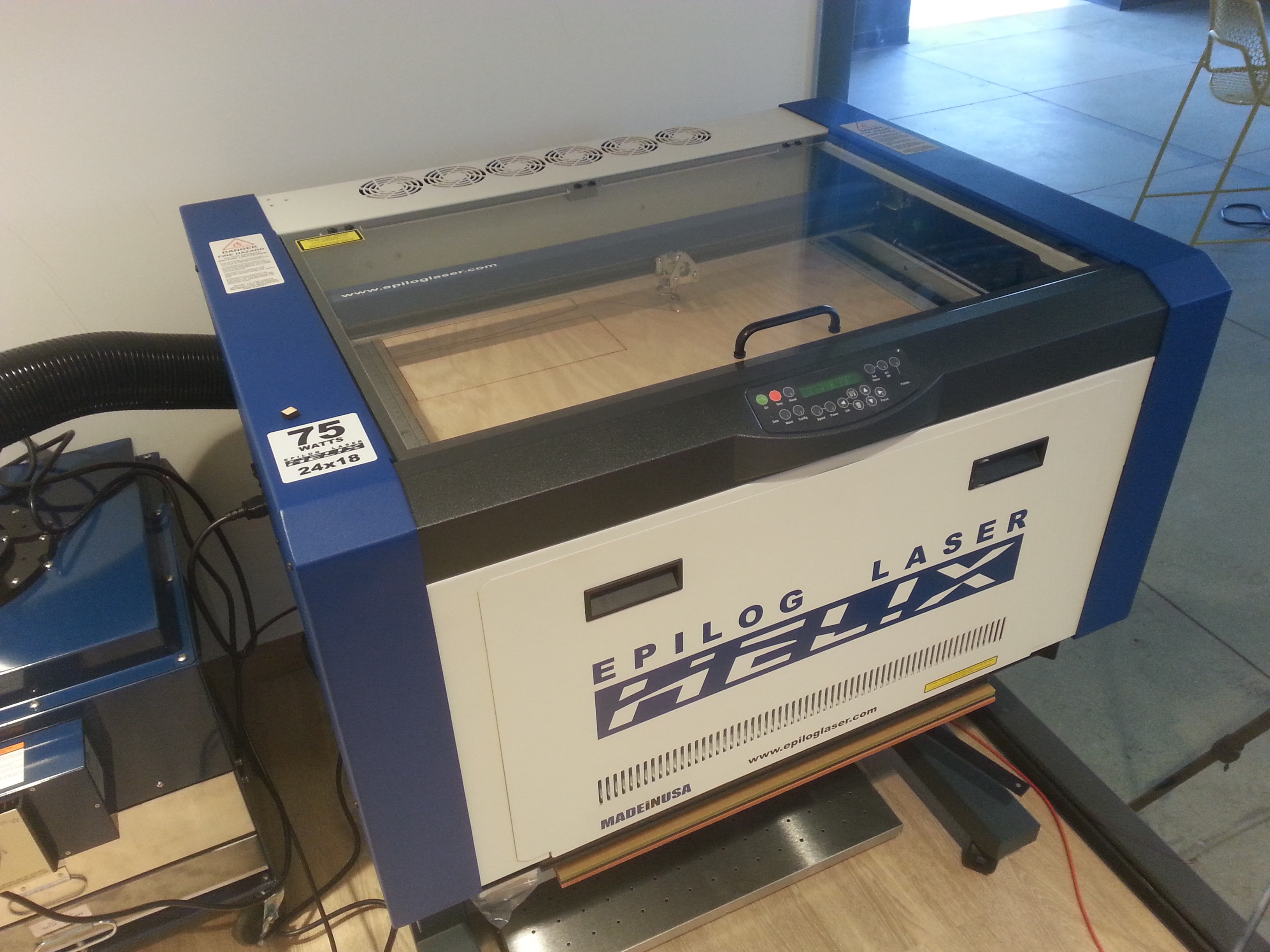
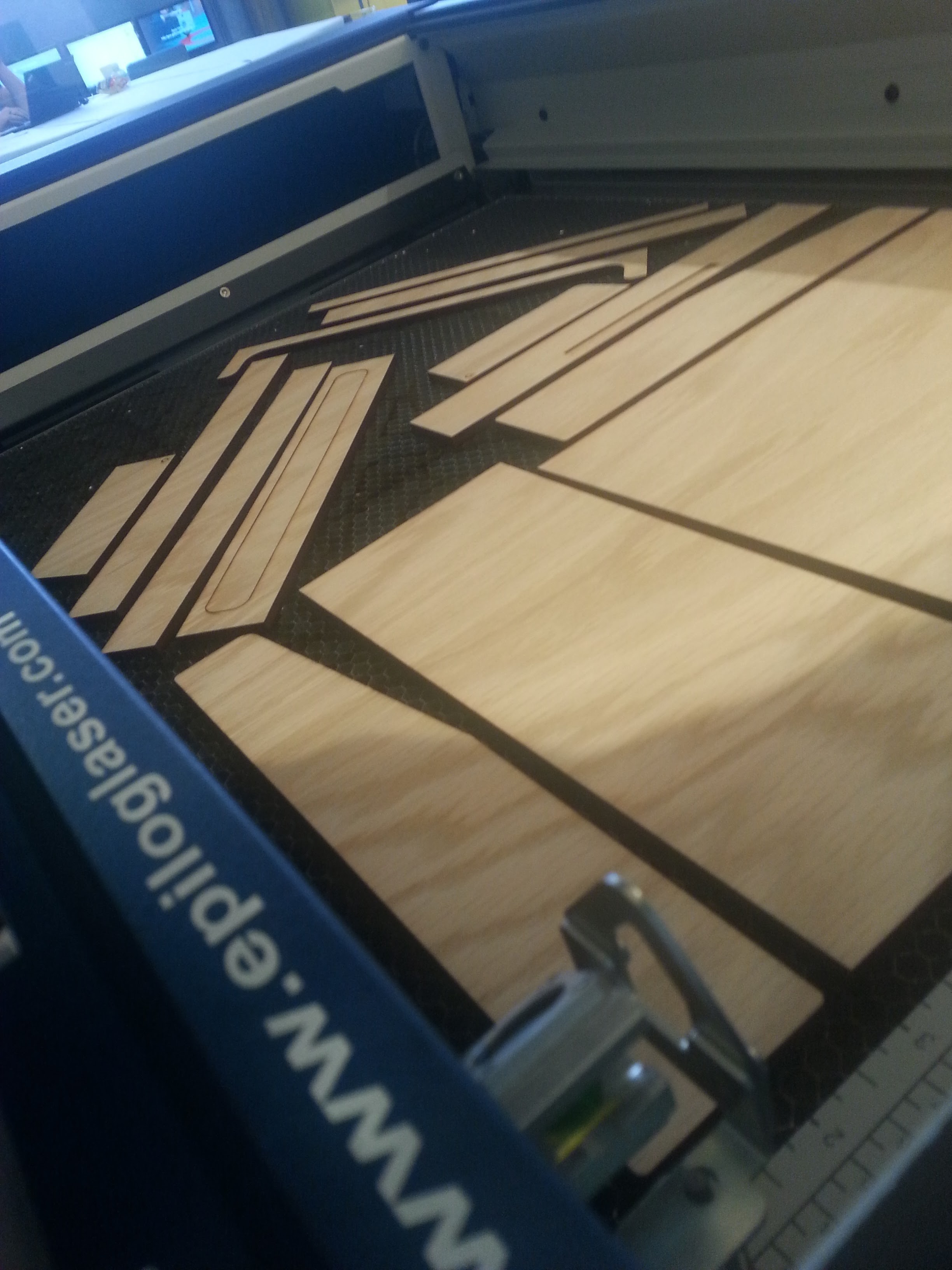
07/14/2016 at 06:34 • 1 commentSo, I am super happy to be part of the very first group of residents at the Supplyframe Design Lab, and super happy to use all of their fancy tools! Unfortunately, the Shop Bot CNC router is still not ready for prime time, so I've been asked to retool to make the first version of the case on a laser cutter. This means some of my rounded edges will be kinda square.
Also, the wood we have is not a full 1/4 inch, so some things will fit together kinda oddly.
![]()
Here is our fancy Epilog Laser Helix. It can cut plywood without seeing it on fire!
![]()
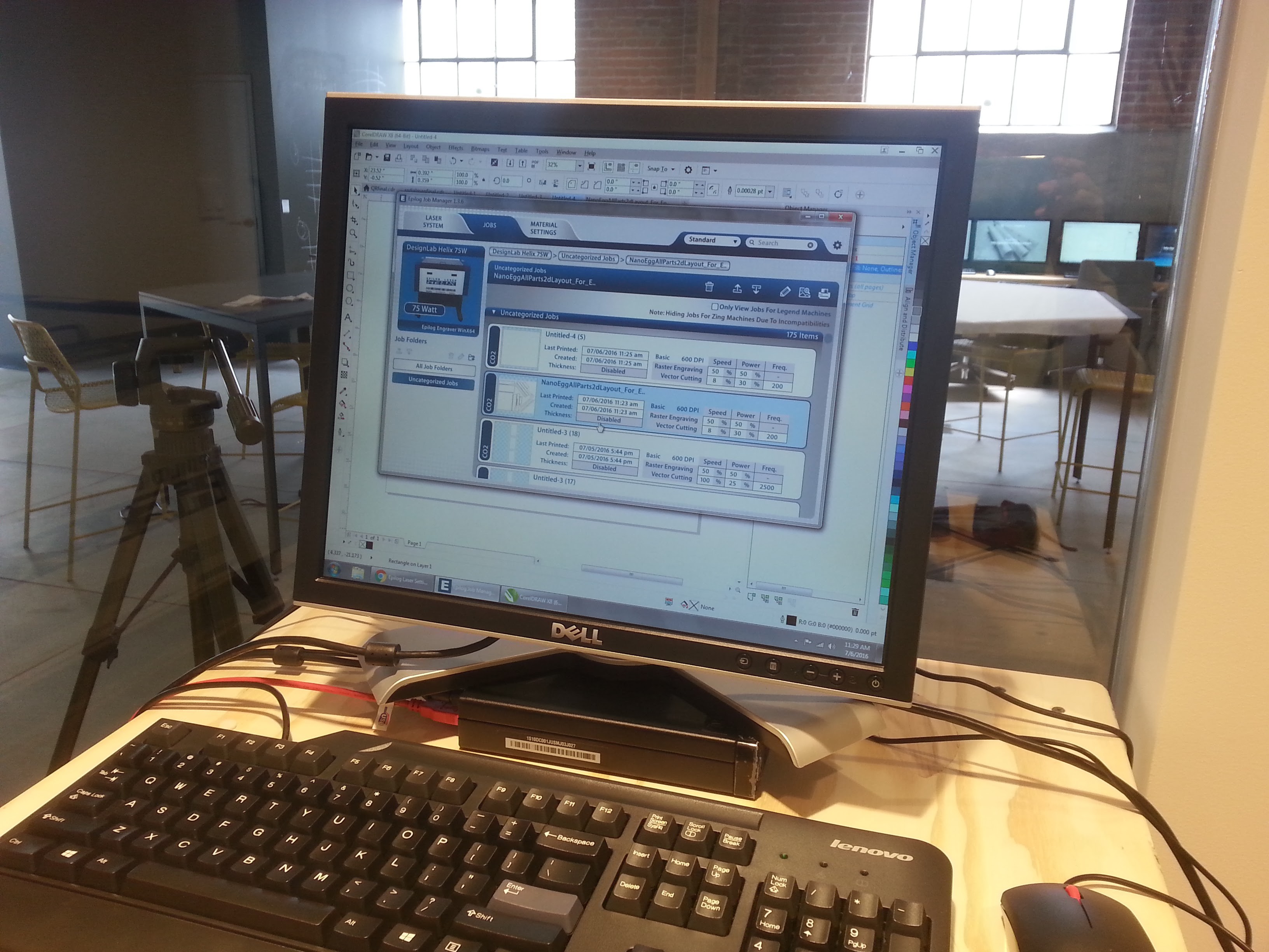
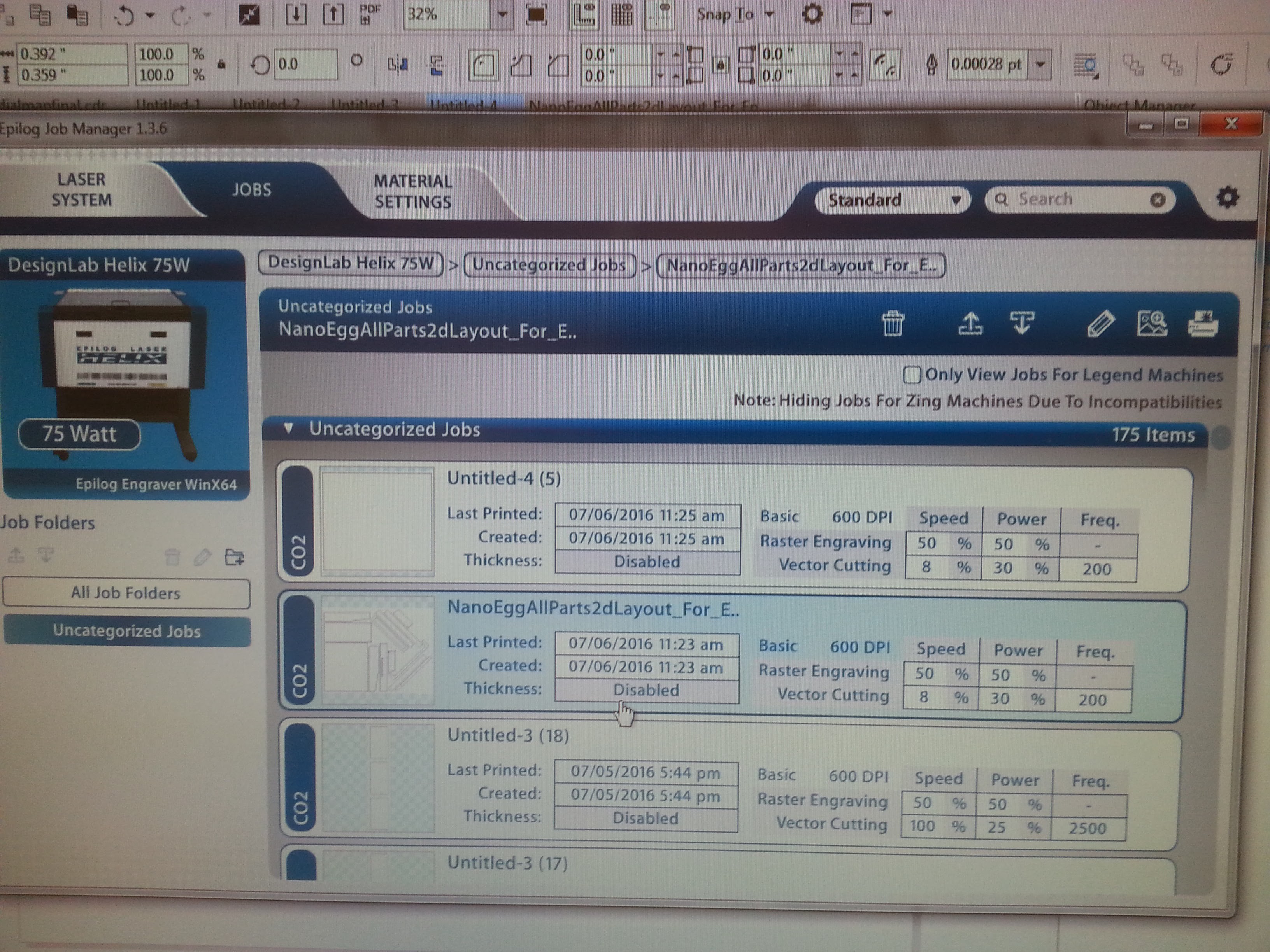
Let's delve into the settings required for that.
![]()
That's me in the middle.
![]()
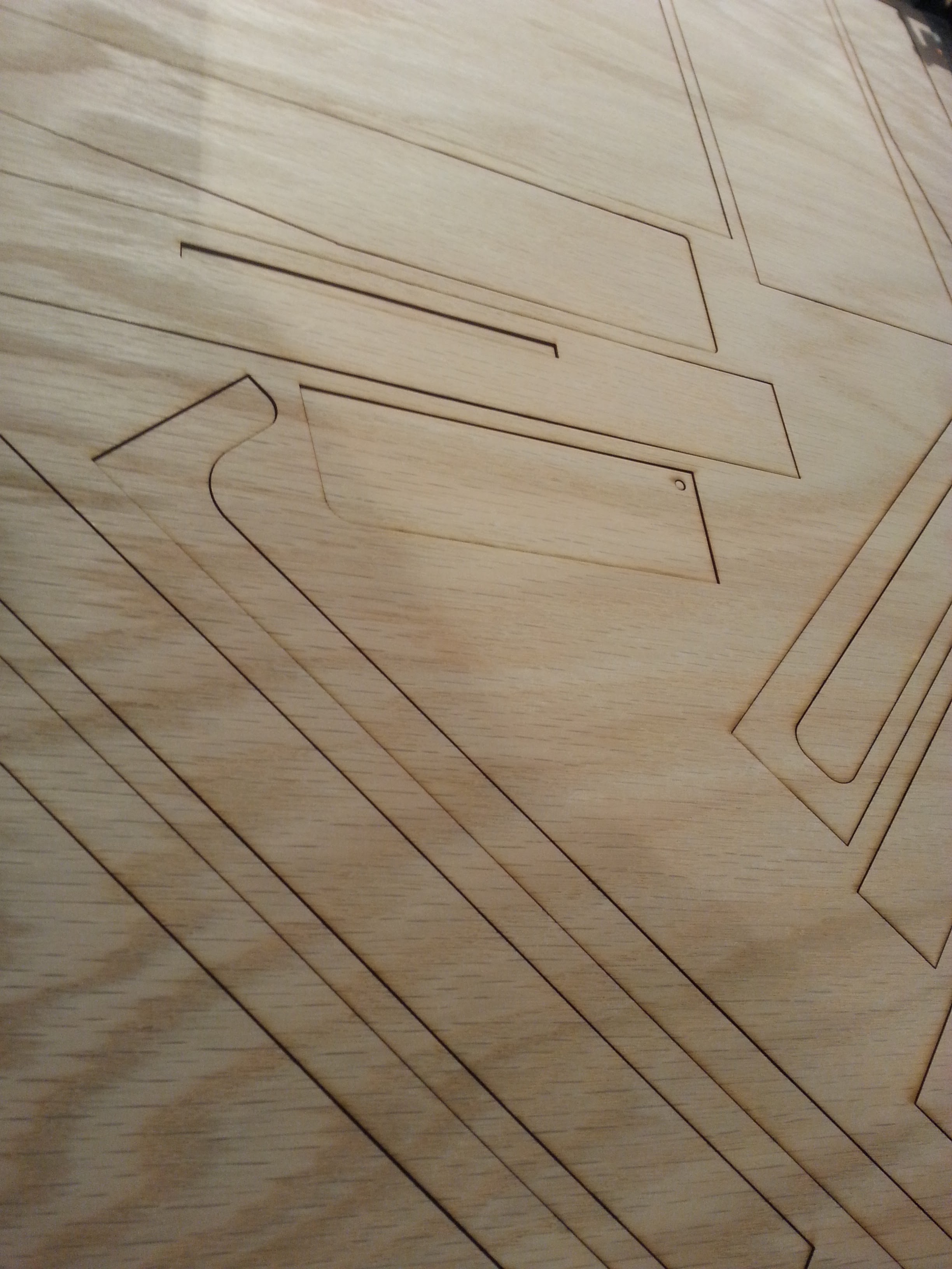
And then it cut a bunch of wood perfectly, the first time. Ah, I do love laser cutters!
![]()
You might notice that the wood is cut without regard to the grain. This was not my choice, but I am at the mercy of the folks running the shop until they certify me for operation of the laser cutter. They said "it is just a prototype, so it doesn't matter." But I feel like I shoulda stuck to my guns on that. The grain did later cause several pieces to break.
![]()
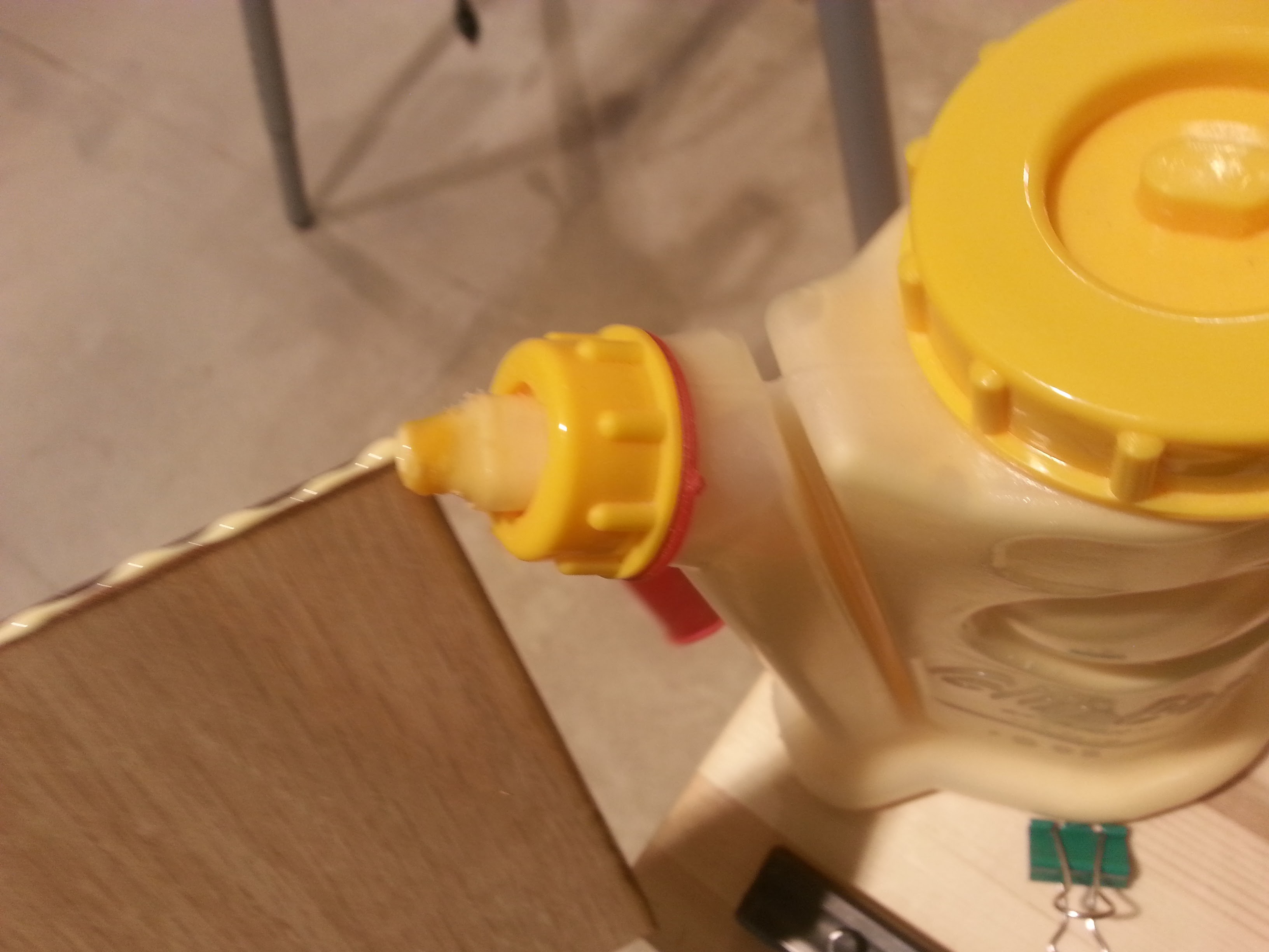
It is too thin to screw or nail, so I am gluing it.
![]()
Clamp it and wait 24 hours.
I'm too tired to do more today. I'll edit this later.
-
Printing the keyboard
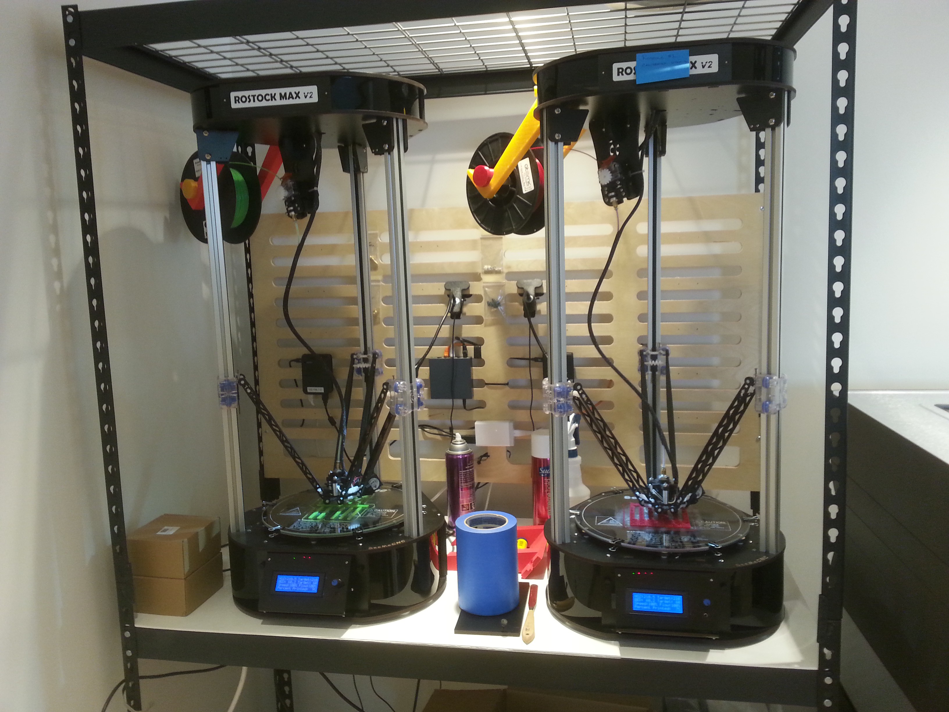
07/14/2016 at 05:42 • 0 commentsSo I managed to get a residency at the Supplyframe Design Lab in Pasadena, and hurriedly got to work on a prototype on day one!
(Note that I am writing this up a week after starting and I am completely exhausted, so mostly pictures.)
First up, 3d print the keybed. I only designed it 3 years ago...
![]()
I'm kinda at the mercy of the folks running the lab for what filament is in the machines at this point, so the black keys are printing in bright optic green, and the white keys in VT maroon.
![]()
![]()
You can already see the upper left corner starting to peel up here. Will it be a problem?
![]()
Oh yeah, it is a problem.
![]()
It is a shame, because the front of the keys is fine.
![]()
Just sand off the sprue...
![]()
The black keys were printed in two parts, which noise need took be glued together.
![]()
Clamp tightly and wait 24 hours.
![]()
Magically, a new set of white keys was printed using the same green filament. We glue these to the black keys to make a whole keyboard part.
![]()
![]()
![]()
The second set of black keys was printed half green and half maroon.
![]()
I pushed paperclips through the mounting holes for alignment and used these lovely tiny clamps to hold this one together while waiting for it to dry.
Next up, the box!
-
Got in Megsy PCBs!
06/28/2016 at 22:47 • 0 commentsThis project is based around the Teensy 3.2, which has some I/O that is only accessible via tiny pads on the bottom of the board. I created the Megsy project to make it easier to access those pads. Although there is an official expanded board available via OSHPark, it lacks a full bill of materials, and requires a lot of surface mount soldering, which I've no experience with.
So I finally ordered some PCBs for Megsy and they came in today. The full story is on the Megsy project log here:
https://hackaday.io/project/11367-megsy-a-homebrew-teensy-3/log/40826-first-pcbs-have-arrived -
Multiplexers: How to expand your input lines
06/20/2016 at 10:53 • 0 commentsWhether you are using the Arduino, the Teensy, or any other microcontroller, you'll probably have an occasion where you need more inputs than the controller can support. NanoEgg is somewhat of an extreme example of that, as it is currently designed with at least 42 knobs, a 24 key keyboard. a touch screen TFT, MIDI ports, audio output, and 2 control wheels. While I've worked to expand the number of I/O lines with my Megsy project, it is still more than the system can ever hope to handle!
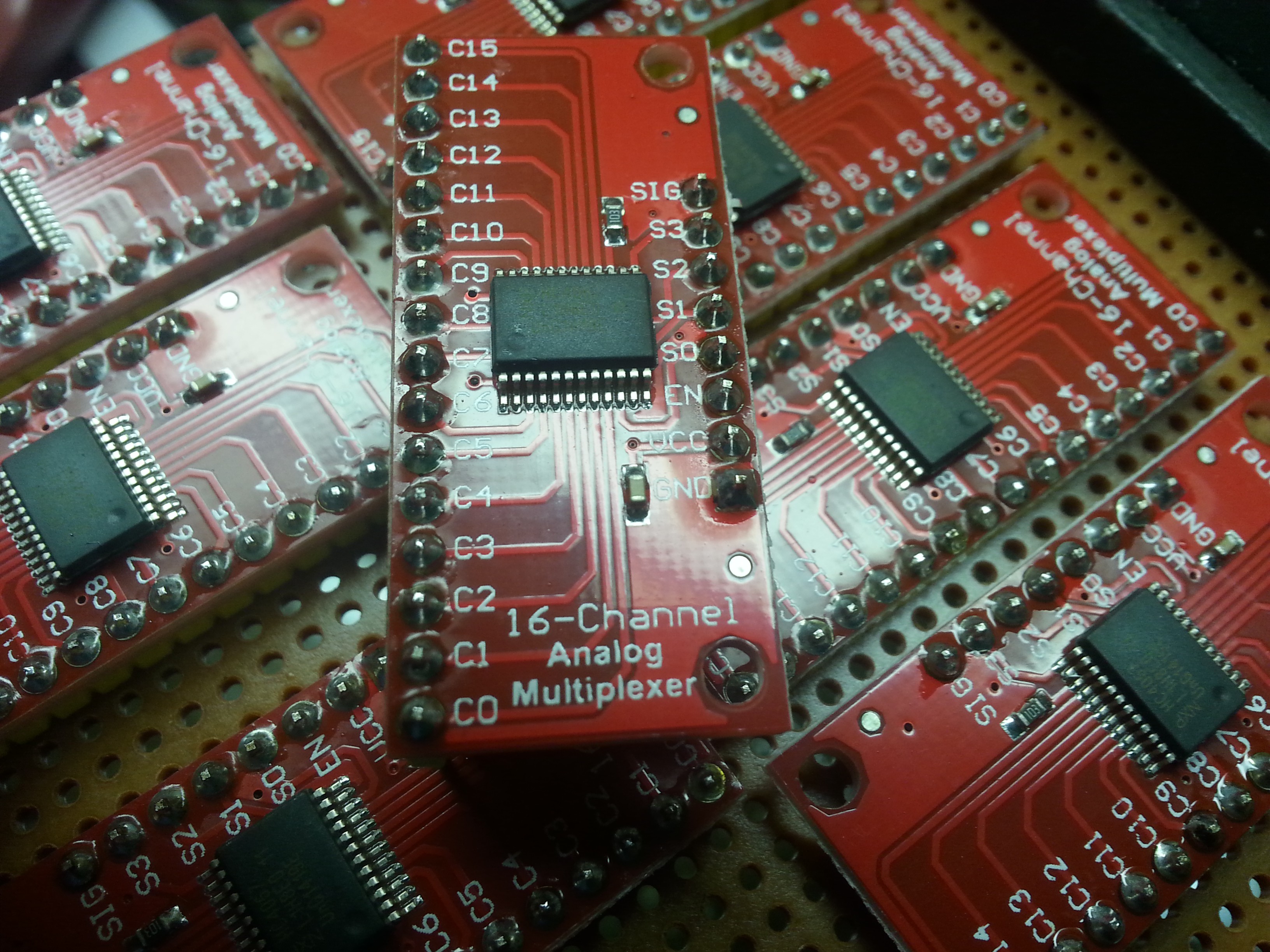
Fortunately, there is this lovely device called a multiplexer that lets you select one channel of I/O at a time from multiple possible channels. I chose to use the 74HC4067, since it handles analog IO, and has a relatively large number of channels. Unfortunately, it was impossible to source a DIP version of the chip, but luckily for me there are some nice Chinese vendors on eBay that sell breakout boards; circuit boards with the surface mount version of the chip attached that long pin headers can be attached to for easy prototyping! I ordered these a few weeks ago and they finally came in.
![]()
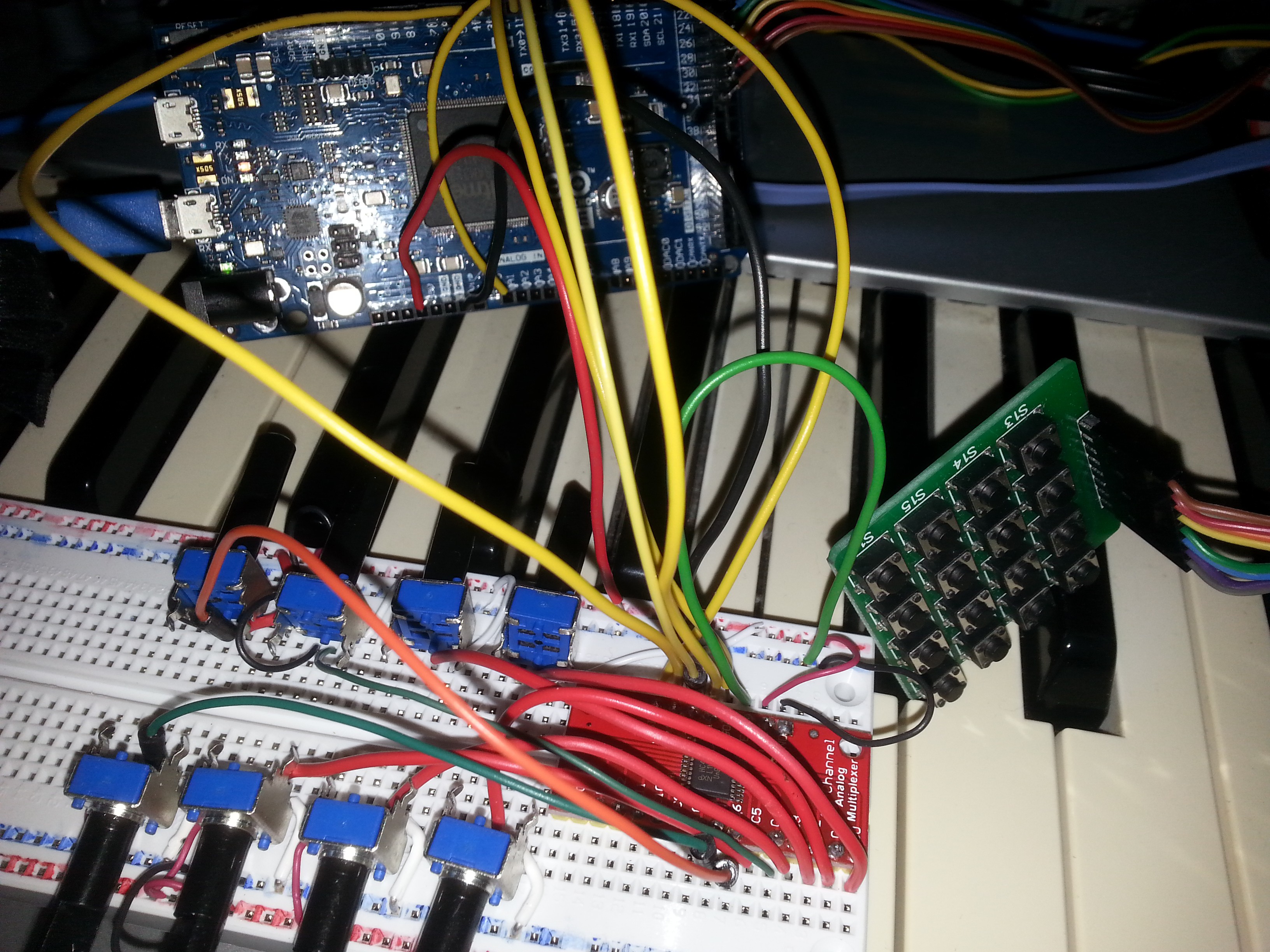
The next step is to test it out, so I built this little circuit. While this chip will support 16 analog inputs, I got bored after eight and stopped there. Here is a circuit with the multiplexer attached to an knock-off Arduino Due.
![]()
To see the best way to wire everything up and how to code a demo, I found a nice reference page at bildr that explained everything.
http://bildr.org/2011/02/cd74hc4067-arduino/While I realized that their code wasn't the most efficient, I integrated it easily into my existing keypad test code and optimized the output so that I could see the knob turning in action.
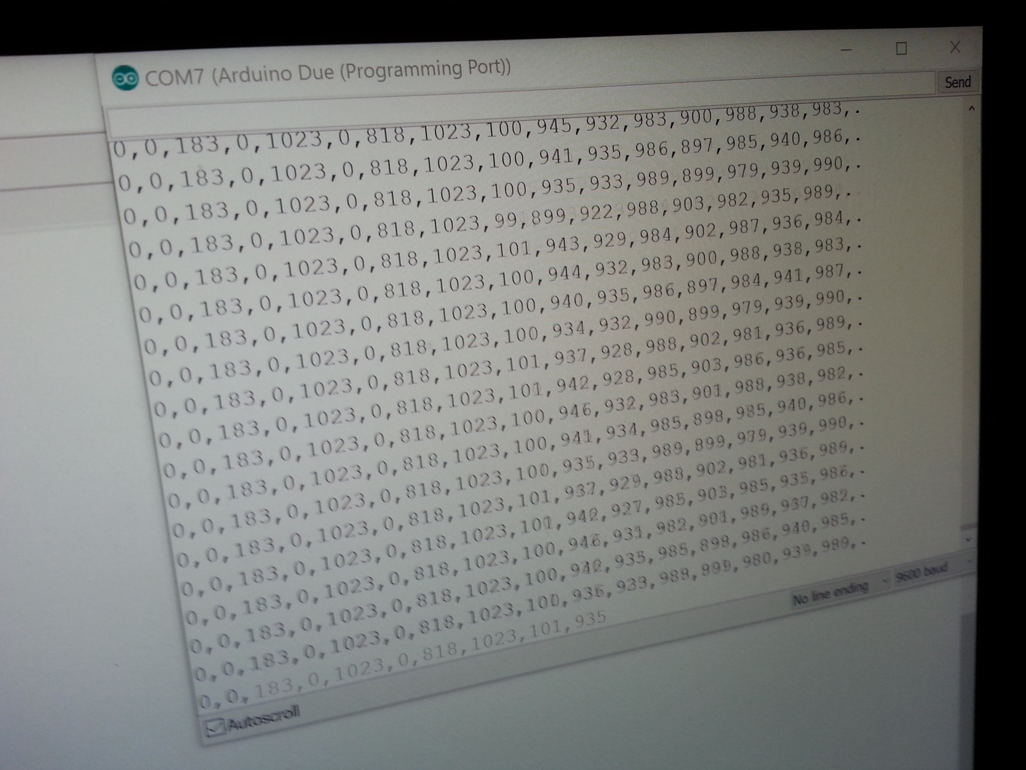
![]()
One thing I have noticed here is that, in comparison to the analog inputs on my Arduino Mega 2560 knockoff, the inputs on the Arduino Due are relatively stable! The jitter is only +/- 1, which can easily be smoothed out with some oversampling. This will give each knob the full range of 0 to 1023, or 10 bits. MIDI CC messages can only handle 0 to 127 ( 7 bits) so this is quite a bit more precision! This may enable me to do both coarse and fine adjustments of values with a single knob, allowing me to eliminate some of the extra knobs I have had to add and thus handle more input parameters without resorting to the touch screen display.
I suppose the next step is to design some sort of reconfigurable front panel than can be built as a printed circuit board, so that I can test different control arrangements. Progress!
NanoEgg Music Synthesizer
A powerful little music synthesizer with a classic look!


 I added some cookies to hold the black and white key sections together too.


 Now that we have these wonderful 3d printed keyboard sections, and have mounted them in the case, we really need some way to electronically tell if a key has been pressed.
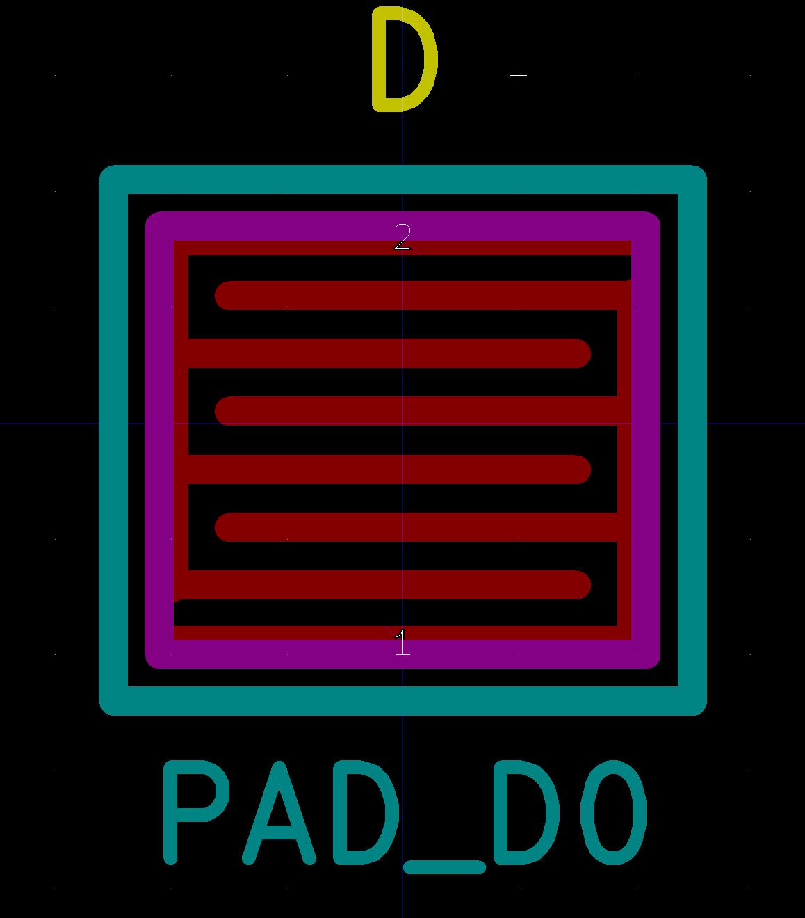


 And the back:


 So shop head Dan had a go at it.


 Although the one on the left has nice large gaps around the traces, the switch contact pads have VERY thin traces. The board on the right is a much better balance and matches the design more exactly.
 The back of the board shows this as well.
 Rather than waste a bunch of 0 ohm surface mount parts, I just bridged the connection between the boards with some solder.


 The spacing wasn't the same, so I cut them up with scissors.


 Here it is, in all it's glory!


 Because we had some trouble printing the keyboards, we couldn't put it all together right away, so we did some test fitting.


 Attach one of my touch screens to the back of the front panel.
 Do a test fitting.