Oskar Weigl
-
Surface mount soldering: Easier than you might expect.
05/10/2016 at 11:52 • 0 commentsThe design of the ODrive is almost entirely surface mount, the only exceptions being some of the heavy duty screw terminals and a couple of rows of headers for IO. This design choice is likely not a surprise to most of you, SMD's are usually cheaper, more compact, easier for industrial production and sometimes the components we want aren't available in any other way!
So SMD it is! However this does pose hobbyists a bit of a predicament. Most people have not done any serious construction with SMD's and they (quite reasonably) think they are a hassle to deal with: this post is about dispelling some of those worries.
Before any soldering can happen, something to solder onto must be acquired. The PCB in this project is only 2 layered, so it could be home-brewed if you are skillful, but we would strongly recommend against that. There are many vias that need plated through hole (PTH), many 0603's in close proximity that pretty much require a decent solder mask and many of the tracks are very thin. Though I think the main reason for going for a 'proper' PCB is that thanks to the hobbyists constantly demanding more quality for less cost from PCB houses, they are very cheap to get manufactured. You can get 10 copies of this board from china for $35 + postage, pretty epic, though there are some extras you should seriously consider adding if your budget allows.
- Extra copper thickness: Most board houses will offer '2oz' copper, which is twice as thick as the standard offering, if you are going to push the board to the limit (and we hope you do) this will help the board handle the 100s of Amps without overheating/burning out. Though you can skip this option depending on the particular application you have in mind.
- Steel solder stencil: All decent board houses will offer you the option to get a steel stencil, where both sides of the board will be put on the same stencil. The stencil varies in cost with manufacturer, ours was $18. This will make your life much easier, though of course there are many ways to skin a cat; you can also use home made stencils using a laser cutter, or commit some time with a solder paste syringe and develop beasty hand muscles ;)
- Coloured solder mask: Why, because sex appeal, that's why.
With the above things in mind we can strongly recommend Elecrow, primarily because their stencils are cheap, but all of the other optional extras are also on par with other board houses. The quality is very good, but nowadays that goes for all of the major board houses catering to hobbyists.
You have your shiny new board, and have ordered the required components from your local supplier (Farnell and RS are good choices in most countries). Time to get soldering! The most important step to get right is applying the solder paste. Having the right amount of paste will save you from most of the pitfalls, as long as the gods of surface tension are on your side. Place your board on the table and surround it with all the spare boards. Have a friend hold the stencil down whilst you pull a bead of solder paste across all the holes with an old credit card, try and get all the holes filled in one swipe, then scrape backwards such that the stencil is mostly shiny steel again. Order obedient friend to lift the stencil straight up. This should leave perfect little blobs of solder, wipe off and start again if there is lots of blobbing.
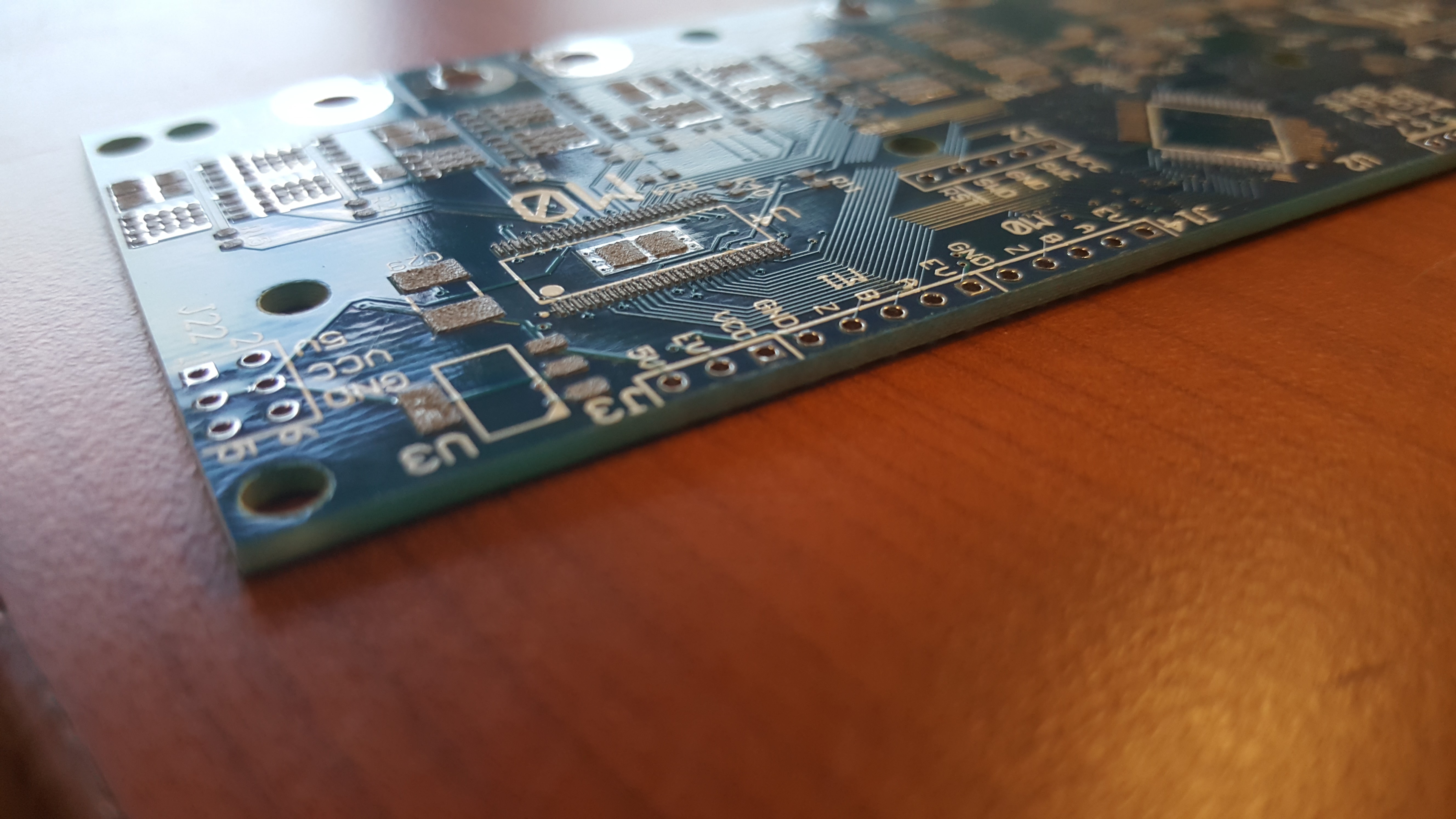
The stencil and board as supplied from Elecrow.
![]()
Nice, square, separated solder piles. Brings a tear to my eye.
![]()
When you are satisfied with your pasting, we can now move onto pick and placing. In industry this is usually done with a big expensive machine, but for us, obedient friend to the rescue! I jest, you can do this yourself, but it is more fun to do it with a friend. One of you can dispense the components, dictate where they should go. The other can spend their time placing the components with tweezers and trying not to smoosh the whole lot with their wrist.
Three at a time baby, yeah!
![]()
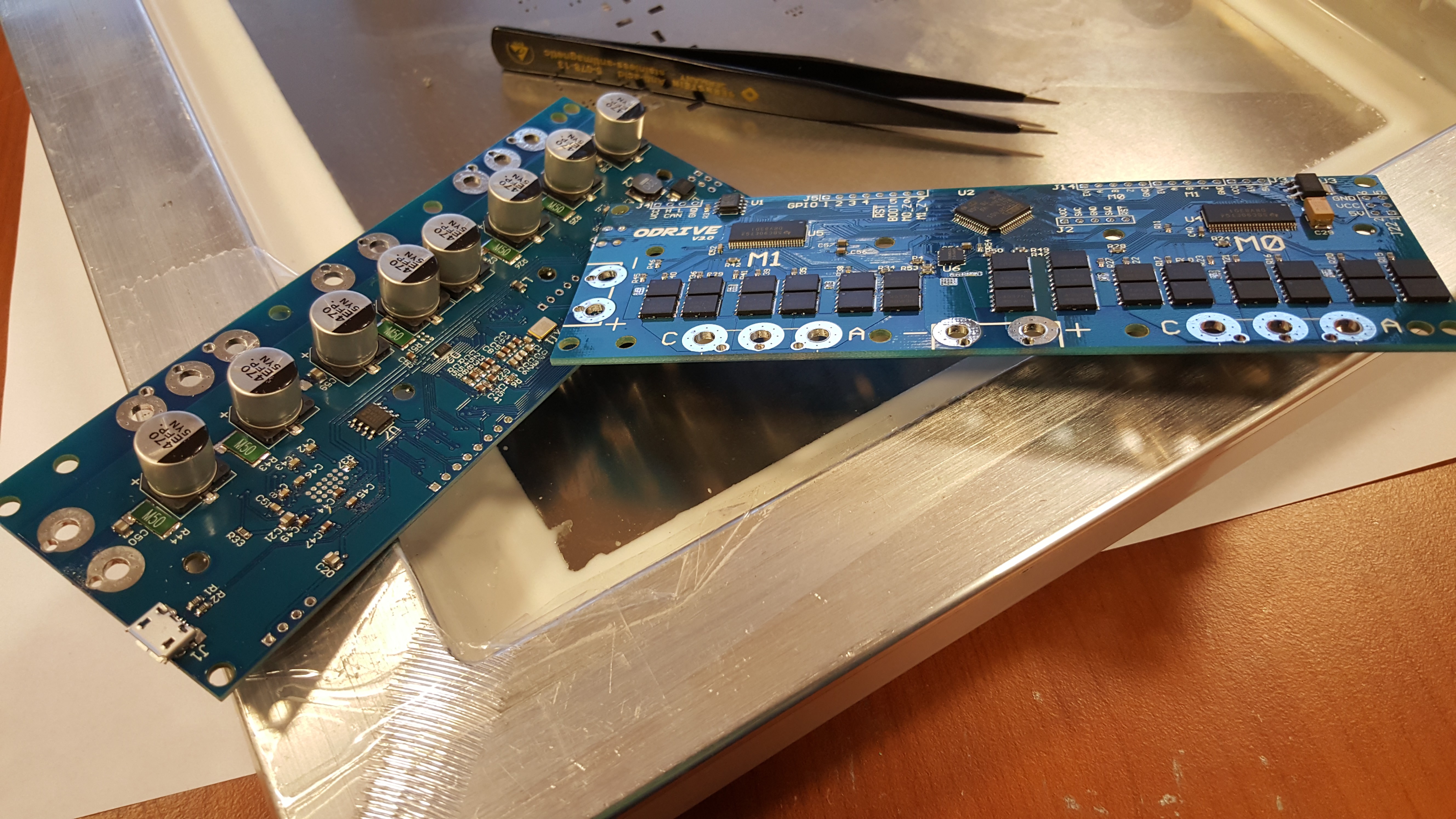
Once all of the components are on the board (one side only) we need to melt all the solder to make the joints. We used a fairly 'proper' soldering oven, which hopefully your hackspace would have, but others use modified toaster ovens or just hot air guns. What ever method you choose, the goal is the same: Make hot, melt solder, wait to cool.
Like a proud mother giving birth!
![]()
Repeat on the other side. You will need to raise the board up on a sheet of wood or similar to stop the components touching the table when you are stencilling. When you put it in the oven again you don't need to worry about the other side, surface tension has got your back.
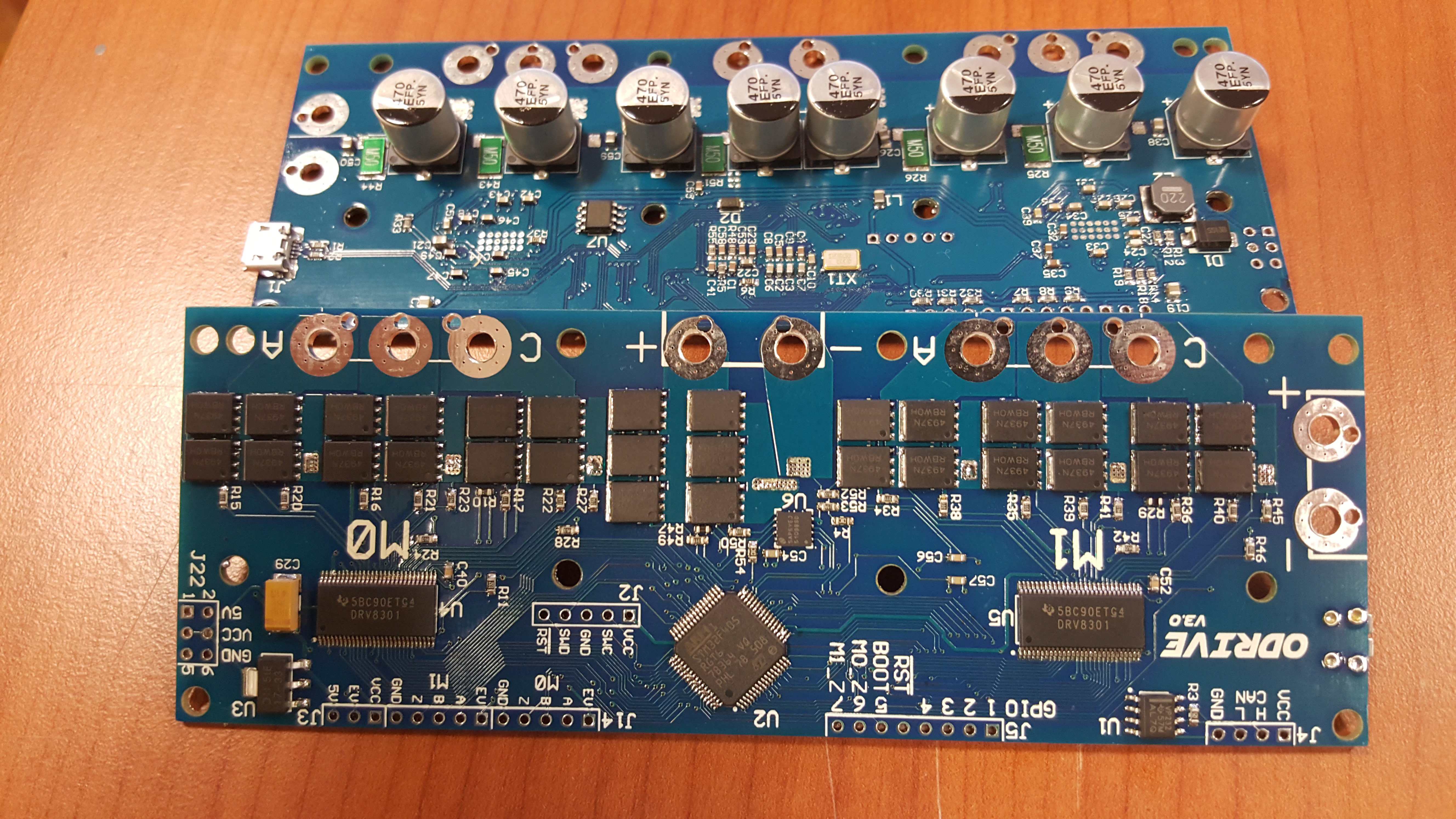
Finally you need to check the board over carefully for errors. There is likely to be a short or two kicking around the large chips. Use some desoldering braid to remove them, add some flux if it is playing hard to get. Now assuming you put your components on the right way around. The job is done. You can now solder any through hole connectors that you will be using, though now that you are a SMD veteran, those are a walk in the park.
Fin.
(These images were taken before reworking solder bridges, a fun excercise for the reader I think)
![]()
![]()
-
Hobby motors in your robots
05/08/2016 at 15:02 • 16 commentsI'm not a mechanical engineer. So what follows is probably not the neatest or most optimal solution. In fact, I would love to see a project with some improved setup. Nevertheless, I would like to share with you what I have learned from using these motors in my robots.
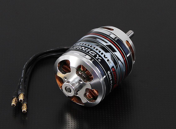
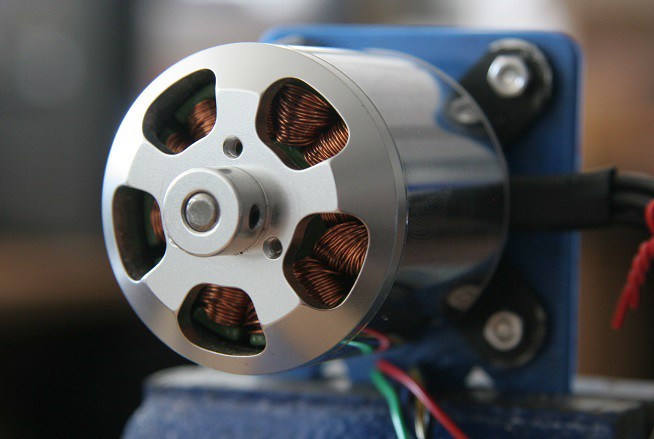
My favorite type of motor (so far) for robotics applications are the Turnigy Aerodrive SK3 series.
![]()
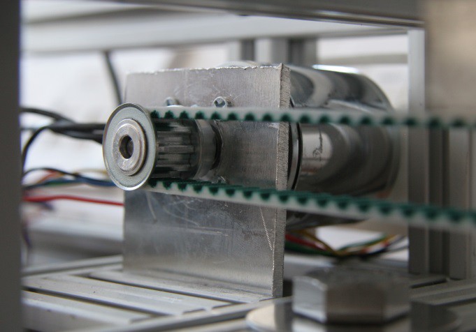
This is for several reasons. Apart from the things that almost all hobby motors have, which is low cost and high power, is that it has a low kv number (more on that later), and has the main shaft coming out of the "back" of the motor. If you look at the above picture, you can see that the mounting plate is on the same side as the shaft. This means that if you attach a pulley to the shaft, and pull sideways on it with a belt, the leverage from the bearing to the pulley is as short as possible. See the below image (which is from the rig you can see in the 3rd demo video) for an idea of what I mean:
![]()
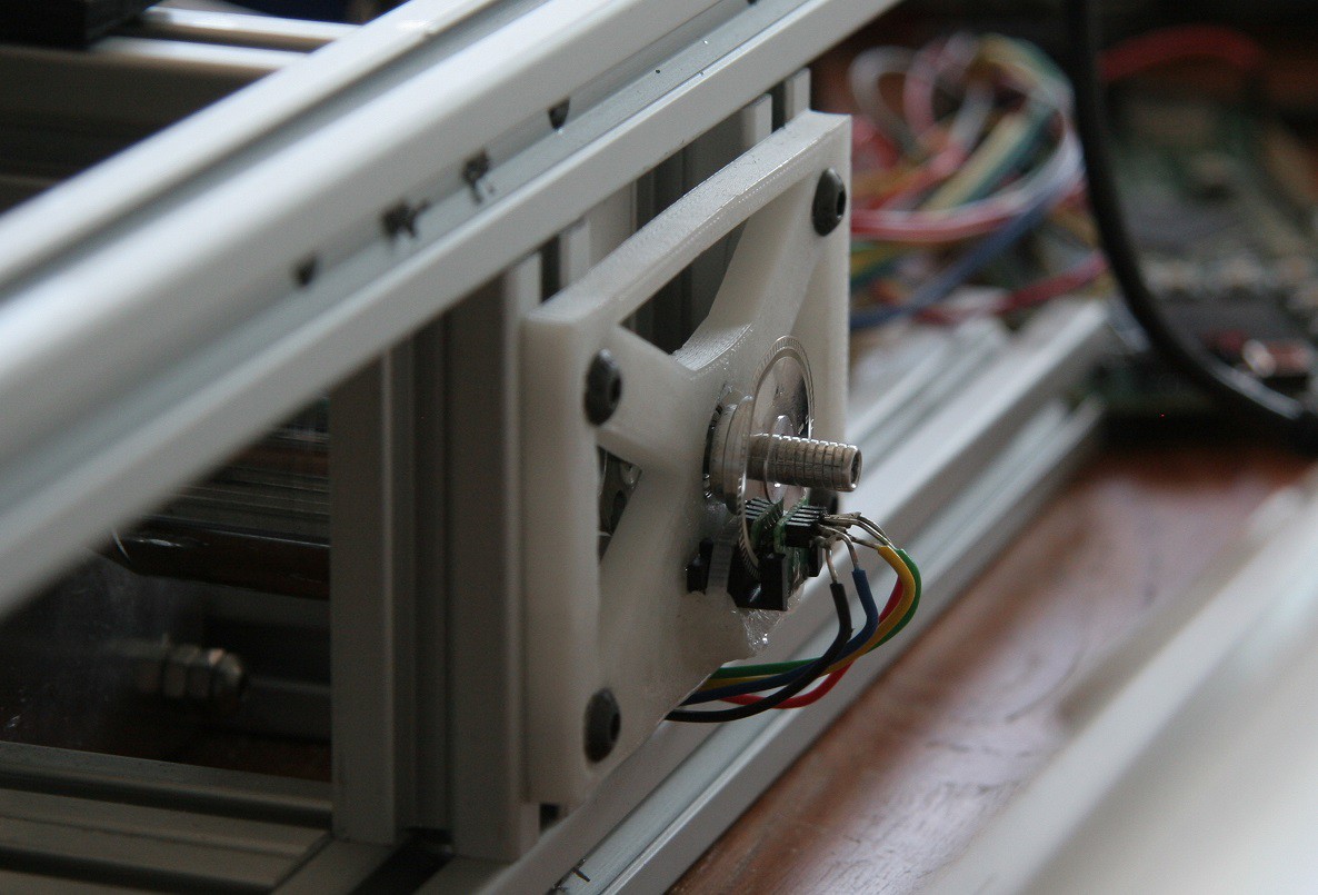
Another great thing is that they give you the possibility to mount something on the spinning side too. The motor even comes with an adapter that attaches to the seen trio of tapped holes and gives you a shaft:
![]()
This is perfect for attaching the encoder:
![]()
For your convenience, I compiled this table of motors that I have had good experience with. The motor used above is the Turnigy Aerodrive SK3 - 4250-350kv.
Motor Price
$Power rating
WPeak Torque
NmWeight
kgHobbyKing Donkey ST4010-820kv 13 700 1.21 0.19 Turnigy L3040A-480G 20 1,000 1.79 0.19 Turnigy Aerodrive SK3 - 4250-350kv 36 1,200 2.36 0.27 Turnigy Aerodrive SK3 - 5065-236kv 56 1,850 4.21 0.53 Turnigy Aerodrive SK3 - 6374-149kv 80 2,250 7.77 0.84
Pick your motor!I made this spreadsheet to help you pick out a motor for your project. Let me know if there is something that needs explaining, or adding.
ODrive - High performance motor control
Hobby brushless motors are incredibly cheap and powerful. However we need a way to make robots out of them. ODrive is that way.