caver.adam
-
Laser Offsets
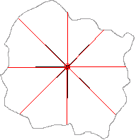
06/28/2016 at 16:38 • 0 commentsIn a perfect world we could get a laser module where the laser shoots straight out of the module and straight back to the detector and is centered at the origin of our gimbal space...but this isn't a perfect world. The detector has to be physically (and optically) seperated from the laser. In the modules I'm considering the spacing is often ~25mm (1in). The first figure below shows how it would work if the laser came straight out of the module/gimbal and was centered at the origin. No transformations of the distance needed. Only a distance and two angles to collect.
![]()
One of the modes that can be different is that the module has a stereoscopic spacing between the laser and the detector and the output can be off-center. If the module is in front or behind the origin we can simply add or subtract distance to adjust. However, if the module is off to the side of the origin we end up scanning an entirely different scene. Fortunately (as shown below) the scene is still scanned evenly, and only the ending location from the center is off.
![]()
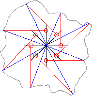
In the blue lines below the actual vector from origin is indicated. Because we know the red vector (we measured it) and we know the offset of the laser emmitter from origin (we manufactured it) we can do a vector addition to determine the actual location of the reading from origin. This only takes one calculation (which can greatly increase computational requirements).
![]()
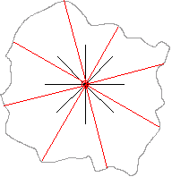
The other problem we can run into is that the laser does not shoot straight out of the module. This is indicated by the manufacturer of the SF30-B (although they do not specify an angle of deviation from center). However, as shown below, this isn't really a problem if the laser is originating at the origin, we simply add this angle of deviation to the angle that is set by our motors. We can do this easily because we are calculating the vector from the motor angle, so we can do the angle adjustment before the vectors are calculated.
![]()
The problem starts when we once again have an offset from the origin.
![]()
Now we have to account for the offset of the laser from center, and for the angle of deviation which is two calculations (and offset is still using a lot of processing power).
![]()
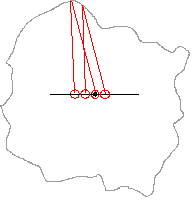
Also, the manufacturer of the SF-30 recommended that the module be centered. They also mention the sensor becomes less accurate over a close range due to parallax error. However, parallax error is based on distance. The centering of the laser only affects distance in that the laser will strike a different place on the target surface (as shown below).
![]()
This leads to some options for using a sensor with a large stereoscopic distance between the laser and the sensor.
1) Switch to an easier to use sensor at a significant cost (because it has to be built from scratch).
2) Center the sensor on the center of the gimbal. This will require software processing to correct the final output based on angle variation and horizontal offset calibration values.
3) Center the laser output on the center of the gimbal.
a) Center the back of the laser at the center of the gimbal with the back of the module aligned with the gimbal axis. This may cause a small offset error because the laser is exiting at an angle. (physical calibration)
b) Perform (a) but offset slightly more to account for the laser angle (physical calibration)
c) Center the exit point of the laser (inside the module) on the center of the gimbal. The module may be calibrated to base distance on the back of the module and the distance results will need to be adjusted accordingly. (physical and software calibration)
Result: Calibration procedures will definitely be needed.
Secondary Result: Build a gimbal wide enough to move the sensor during testing and figure it out later with a design of experiments.
-
To laser cut or to saw cut?
06/27/2016 at 14:08 • 0 commentsMy ABS sheet and lazy susan have arrived to its time to begin making the gimbal fixture for the project. When I asked what the options for cutting at Lvl1 were I was told laser, shopbot, or regular saw. So now I'm trying to learn whether it is even possible to cut ABS on the laser cutter. I figure worst case I'm told now. Second worst case I try to cut it but have problems with the heat and have to buy another sheet of ABS.
Last night I put together a draft vector file (see uploads) to use on the laser cutter. A 3" square base with pilot holes for the lazy susan and for attaching my shaft coupler. A 6" square base for holding the batteries, electronics, yaw motor, and vertical uprights. A vertical upright with pilot holes for either a nema 17 motor or a nema 11 motor (rotated 45 degrees). A vertical upright with pilot holes for the slip ring. A couple bases for the vertical uprights. Two pair of triangular braces for the vertical uprights. The lidar platform (with no holes). Two end pieces for the lidar platform with center pilot holes for the motor or slipring shafts. I might still make some changes, so I've temporarily left the cyan lines that I used to determine hole spacings but these need to be deleted.
Next step: Find out if I can laser cut this. If not...I'll have to mod the file slightly for cutting with a saw...
![]()
-
A discussion on motor selection
06/23/2016 at 13:25 • 0 commentsA lot of people that I talk to about this gimbal think that I should be using servos for the motors. The main reasons seem to be that servos are easy to use and have built-in encoders (in the form of a potentiometer). However, these two items don't really cover the requirements for the project. The requirements is the starting point for identifying a motor selection.
Requirements:
1) Evenly distributed - If the distance between steps of the targeting is not evenly distributed the 3D lidar image will be stretched and skewed. This will likely prevent multiple shots from being registered together into one larger shot. A high quality encoder should not have this problem, but a low quality encoder might.
2) Highly Repeatable - If there are variations in targeting from one run to the other we will have issues with registering shots together.
3) >500 targets per second ( >1200 preferred ) - The device has to move fast enough that we can capture an entire sphere with 0.5 degree resolution (0.25 preferred)
4) Better than 0.5 degree resolution.
5) 360 degree rotation.
6) Low amounts of bounce after moving a step to next target. - Waiting for bounce to dampen requires time and slows down the process. Bounce also increases error and uncertainty. This is a downside for steppers which have some vibration during normal running.
7) Known direction with respect to earth. - note that no motor can give this information on it's own. A 6dof compass is required for determining orientation relative to earth. (And technically, you can use registration in post processing to overcome the orientation issues).
My reasoning:
The reason that I selected stepper motors was primarily because of my first requirement that my image be evenly distributed and my second requirement that the targeting be highly repeatable. Also, steppers are able to meet all of my other requirements. Also, I can always switch to servos in a later phase of the project. I'm testing this project at every step of the process. And steppers are cheap.
-
Ordering Project Base
06/22/2016 at 15:45 • 0 commentsLast night I began working on ordering the base for the project. Some of the decisions that needed to be made was how to attach the base to a tripod, how to make sure the base can turn freely on the top of the tripod, and how to attach the yaw stepper motor to both portions of the base plate.
After a bunch of research it was decided that I should make my own shaft connector. This needs to connect the shaft to a base plate which is 90 degrees away. For this I will use a 0.25" thick aluminum sheet cut to 1.5"x1.5" with a hole drilled sideways and tapped to use a 4-40 set screw. Since I was doing this already, it made sense to drill and tap a similar sheet of metal with a single 1/4-20 tapped hole to mount the project to the tripod. These aluminum sheets will be screwed to a sheet of ABS which will attach to a lazy susan. All parts are on order but the cheap ABS won't arrive until July. Pictures will be posted once assembly begins.
While I was at it, I also ordered some power supply materials for the project. Because my caving lights use 18650's I looked into whether they would work for the project. For $10 its possible to get a 4 pack of these batteries that have a 2000mAh capacity (measured by reviewers). They also have been verified to maintain more than 3A of current. Since my project uses 0.7A per stepper plus 25mA for the Arduino, plus up to 250mA for the SF30-B sensor, I am going to be using less than 2A of current as a rough estimate. That means these batteries will be able to supply enough current and should run at least an hour. Good enough for the prototype model.
I already have some switches and assorted parts at home to make this work. Once all the materials arrive I should be able to make the base plate and to attach the first stepper, batteries, and Arduino to it. It'll still be on a breadboard but you have to start somewhere.
-
Copy of the 3D model concept
06/22/2016 at 00:46 • 0 commentsThis is the original CAD concept. There are a lot of changes that will occur before it is done. For instance, a lazy susan will be added, and the attachment points will be changed.
-
First Motor Run
06/21/2016 at 01:47 • 0 commentsFun with hooking up my first Stepper today. Hooked up my 0.9deg 1.2A Nema 17 Stepper up to my A4988 driver and ran it through it's paces. I'm using an Arduino Uno with pins 4,5,6 for direction,step,enable. For the rest of the hookup I modified the instructions at: http://howtomechatronics.com/tutorials/arduino/how-to-control-stepper-motor-with-a4988-driver-and-arduino/
First results were pretty awful. Then I realized that the code from that page was for different pins than I was using....ooops!
I modified the code to make it easier to track timing and to change my rise and fall times for the step signal output. I also added a jumper on the logic voltage pin so I can set the motor to partial steps on the fly. Then I ran the motor at different speeds. I'm using a nice blue paperclip to indicate direction today until I can throw something together with a set screw.
Microseconds
DelayFull Step [0.9deg]
(time per rotation)Half Step [0.45deg]
(time per rotation)Quarter Step [0.225deg]
(time per rotation)500us Runs (408ms) Runs (816ms) Runs (1632ms) 250us Runs (206ms) Runs (412ms) Runs (824ms) 125us Stalls Runs (210ms) Runs (420ms) -
Trying out potential steppers
06/16/2016 at 17:19 • 0 commentsI'm back in town and my first two stepper motors have arrived. Plan is to hook them up and determine if they have a chance in meeting my needs. First step is to test them unloaded. Then to re-test them loaded with approximated inertial loads.
Here's the motors:
Bipolar 12-24V 1.2A 0.9deg 3.0ohm 2.2mH Nema 17 Stepper with 15.6oz.in holding torque.
Bipolar 3.8V 0.67A 1.8deg Nema 11 Stepper with 8.3oz.in holding torque.
Accuracy Testing plans:
1) With "second hand" attached to shaft run motor 1 continuous cycle and measure offset (if possible). Run 1000 continuous rotations and check degrees offset from starting position to determine average error = offset / 1000.
1a) full step 1b) half step 1c) quarter step 1d) eighth step
2) With "second hand" attached to shaft run motor from starting position 0 degrees to 320 degrees (relative), stop, and reverse direction return to 0 degrees. Perform one time for measurements. Perform 1000 times in order to get average error.
2a) full step 2b) half step 2c) quarter step 2d) eighth step
3) Repeat steps 1 and 2 with an inertial load attached.
Timing Testing plans:
1) Run loaded motor in continuous rotation for 100 cycles with timer and measure time to complete. Calculate average time per rotation.
2) Run loaded motor from 0 to 300 and back for 100 cycles....etc.
-
First small steps
05/12/2016 at 21:46 • 0 commentsCurrently the sensors are a bit out of reach because one is out of stock and the other is out of my price range. So I've decided to start working on the motor components of the device. The current plan is to use steppers that are driven at half or quarter steps to get a nice smooth motion for the gimbal. The gimbal only rotates in 2 axis and depending on the sensor selected the steps required are only 0.5 or 0.2 degrees respectively. I'm hoping that rounding to 0.45 degrees and 0.225 degrees won't be a problem. Motors and drivers are ordered and on their way. Once testing and selection of motors is done I'll source the rest of the hardware for the gimbal body.
Open LIDAR
This project is to build a motorized gimbal mount to convert a laser distance module into a 3d LIDAR.