-
Back At It With Some New Stuff
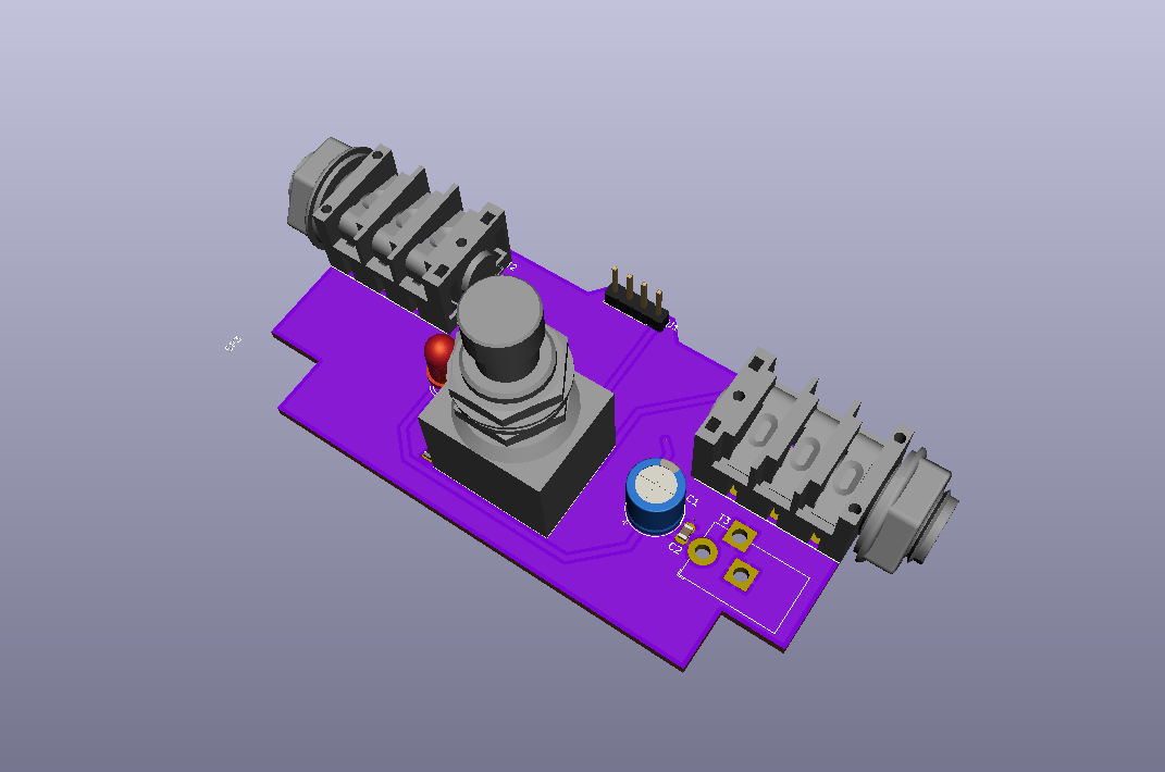
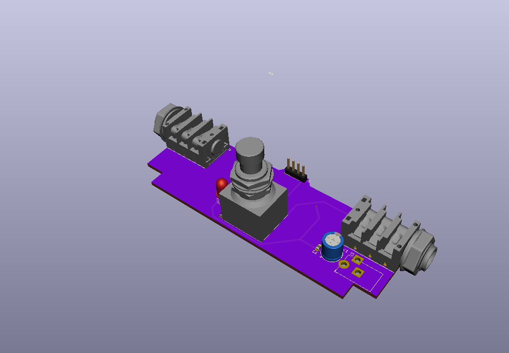
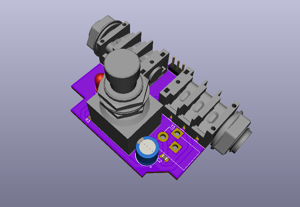
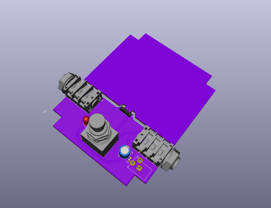
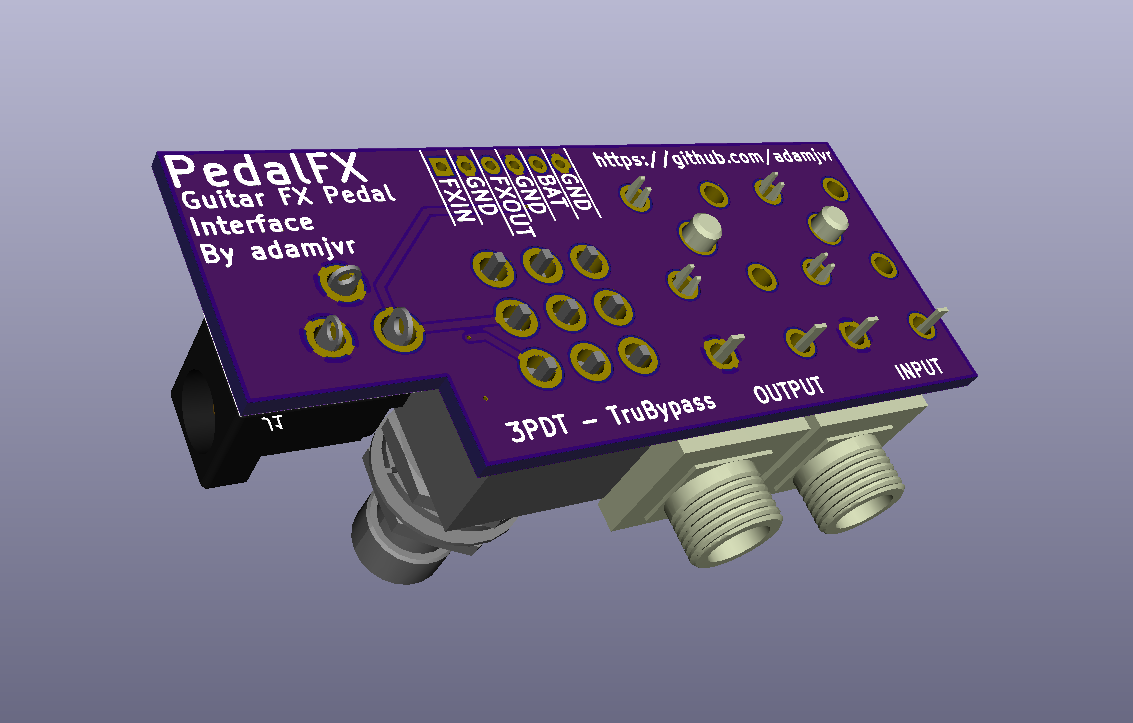
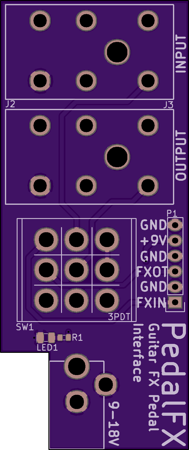
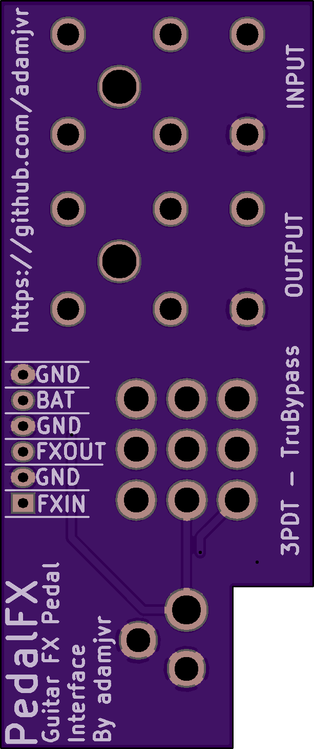
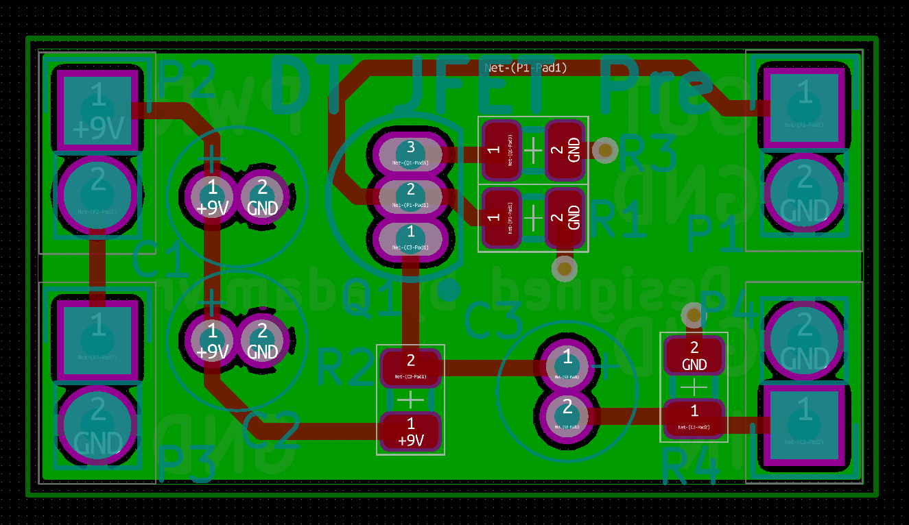
05/11/2019 at 20:41 • 0 commentsHey folks this project is active again for the time being!! So I like guitar pedals and I want to make a few of my own, first things first is to revise PedalFX into something that makes more sense. Announcing PedalFX2 for 1590B and 1590BB vertical/horizontal. This board contains all the switching and in/out for making a guitar pedal, got somehting that has a audio in and out ? turn it into a pedal with this board in minutes!
![]()
![]()
![]()
![]()
There you have it, the images are self explanatory, I should be getting boards made at OSHPark by the end of the weekend, I'll post if there are any problems with the boards after that have at it and make some crazy FX boxes!
-
New Fangled tubes
10/24/2016 at 08:48 • 0 commentsThese new odd style tubes are interesting and given that a few people are building amps with them I figured I'd through my hat into the ring. Gonna go for a hybrid design microphone preamp with one or two of those tubes in use. Stay tuned more to come ! ;)
-
Parts!!!
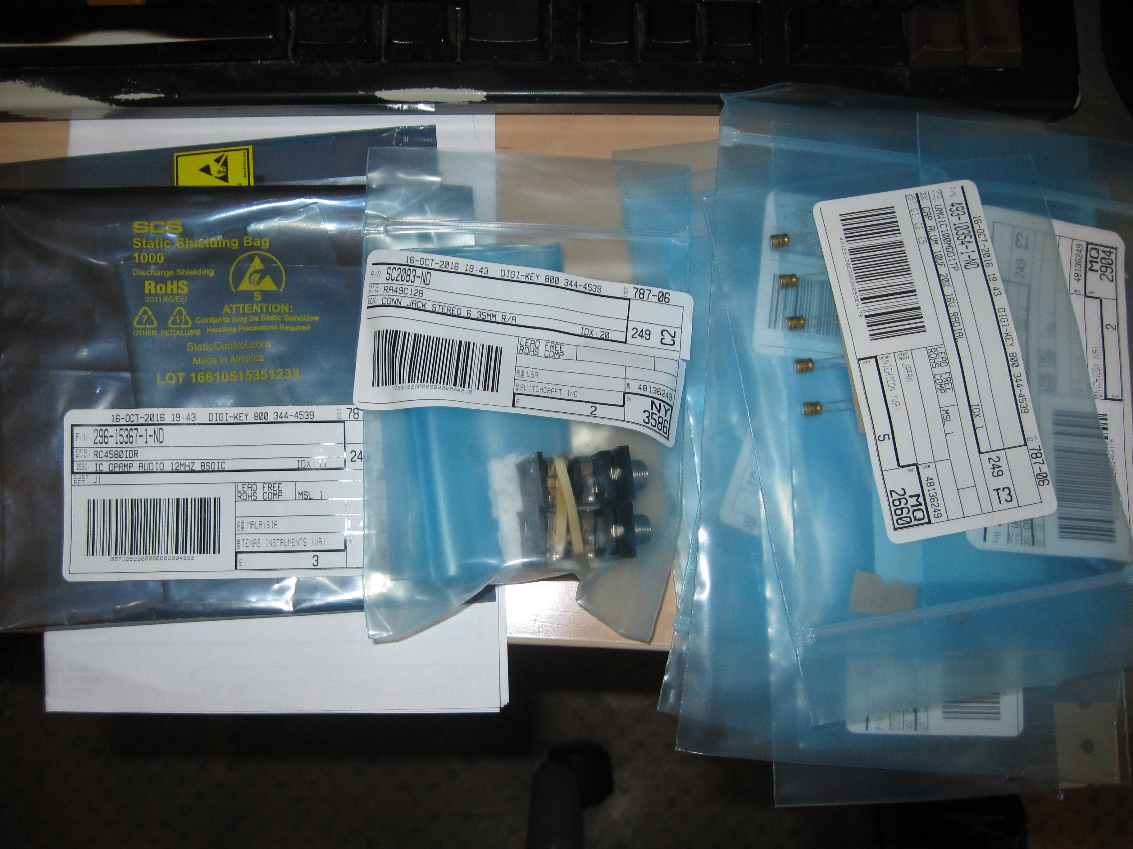
10/20/2016 at 18:12 • 0 commentsToday my digikey order arrived with parts for the DT JFET Pre. I'm going to solder up one and see how well it works with my component selection and board design. For the purpose of keeping my sweet Squire Vintage Modified Mustang guitar from being defiled, I'm going to mount the preamp in either a pedal enclosure or just solder up connectors. This preamp design (http://www.till.com/articles/GuitarPreamp/) is typically mounted inside the guitar as it has no controls for volume level or tone, it relies on the guitar's tone circuit. In the case of mounting it in an enclosure, it would just be a hammond box with no external controls, just power, in , and out all mounted with a PedalFX board. Stay tuned and follow the project to find out what I end up doing with it!
Obligator Parts picture:
-
PedalFX - Guitar Pedal Interface board
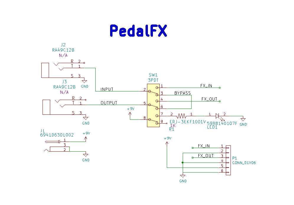
10/12/2016 at 20:27 • 0 commentsSo a while back I mentioned I would be designing a PCB for making the process of taking and audio circuit and putting it inside a guitar pedal enclosure. The concept is inspired by the user mysticwhiskey, you can read more about his board in the project details section. The board is essentially the true bypass wiring that most guitar FX pedals use but as a compact PCB. My board is essntially the same except for moving the power input connector and using completely different components. My schematic is as follows:
![]()
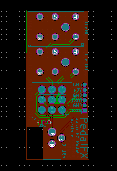
PCB:
![]()
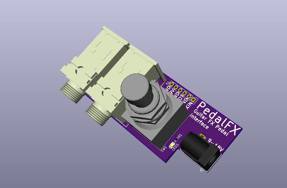
3D Views:
Top
![]()
Bottom:
![]()
So its a fairly simple PCB but will make dropping these audio projects into guitar pedal enclosures super easy. The notch in the corner is geared towards aluminum hammond enclosures, this notch will allow the PCB to be tight up against the enclosure walls right in the corner maximizing space. The boards are gonna be made through OSHPark usng the 2 oz copper spec they offer, this will allow me to keep the board compact and make up for the trace witch limitations caused by the pad size on the 3PDT switch.
OSPark Renders:
Top Bottom
![]()
![]()
Thats all for now until I get PCBs in the mail. Stay tuned on the DT JFET Pre build and check out my other projects !
-
DT JFET Pre Updates!!!
10/11/2016 at 23:28 • 0 commentsHey so its been a while since I touched this project but it hasn't been forgotten. A user on this site was very interested in the DT JFET Pre I designed within this project, so I got back to work on it :).
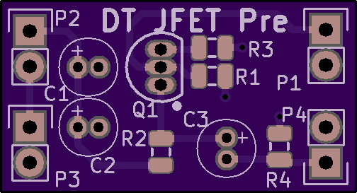
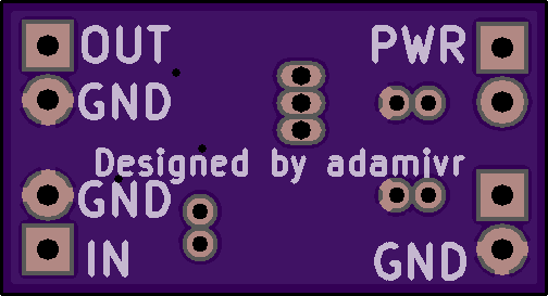
So when I went to get PCBs ready to order I realized that the git commit with the finished board was never pushed. At the time I couldn't find where I put my laptop's backup so the board was essentially lost. I decided to redesign the board in KiCAD, its a little bigger but here it is:
![]()
OSHPark Renders:
Top:
![]()
Bottom:
![]()
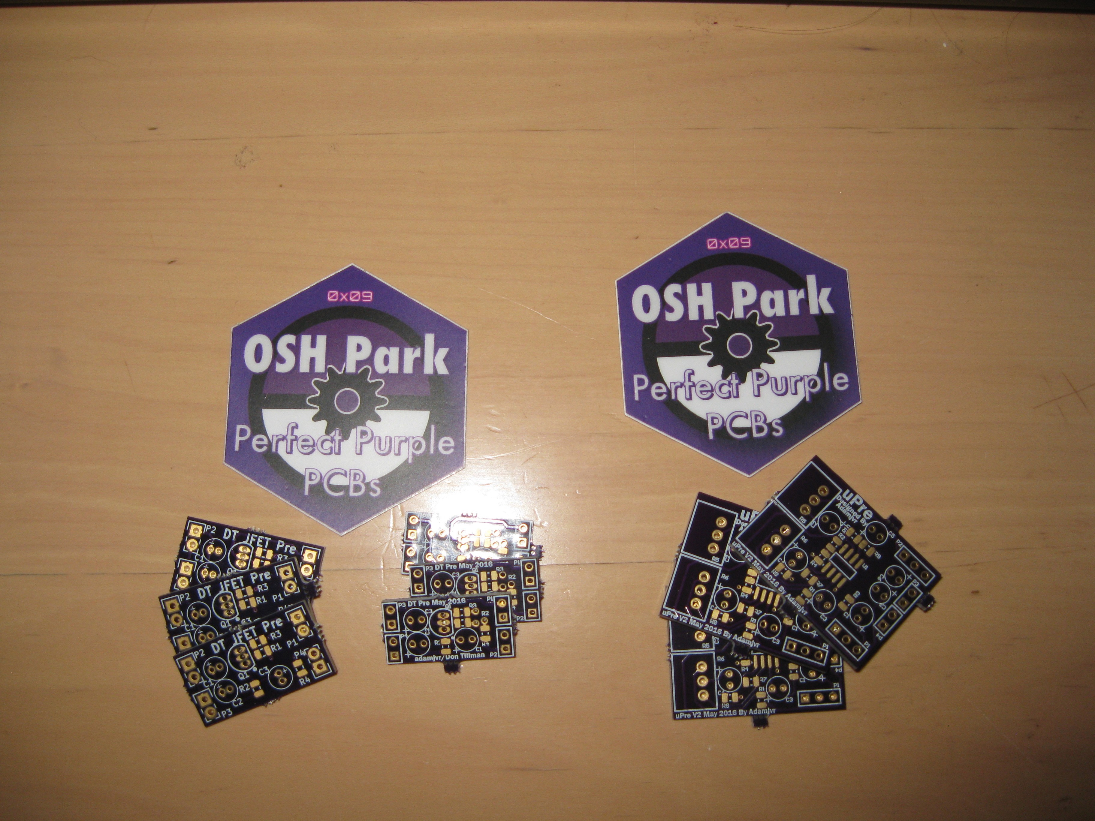
So after doing a quick redesign I produced gerbers and did a quote with OSHPark to have it made. Around the same time I was ordering some other boards and found out that I had my laptop's backup on a flash drive when shuffling through files. So I decided to order both versions from OSHPark and they arrived today:
Also in this update I have the bill of materials, which are viewable below and available as open document format in the files section of the project page. The BOM:
Symbol Value Package Quantity Digikey Part Number Manufacturer Part Number Price Comment C1 4.7uF 4X6mmCAP 1 493-10381-2-ND UMW1V4R7MDD1TP $0.36 C2, C3 10uF 4X6mmCAP 2 493-10354-1-ND UMW1C100MDD1TP $0.36 P1, P2, P3, P4 Header 2 HDR1X2 4 Header 2 Q1 2N5457 TO-92A 1 2N5457-ND 2N5457 $2.19 R1 6.8K R0805 1 1276-5320-1-ND RC2012F682CS $0.10 R2 3M R0805 1 1276-5448-1-ND RC2012F305CS $0.10 R3 2.2K R0805 1 1276-5290-1-ND RC2012F222CS $0.10 R4 51K R0805 1 1276-5379-1-ND RC2012F513CS $0.10 Total $3.31 Its a pretty inexpensive build even including the PCB cost which were around 4 dollars each for a round of three from OSHPark. Now we wait on a digikey order to arrive and we're off to the races, stay tuned for more to come!
-
Tone Stack Progress and New Project
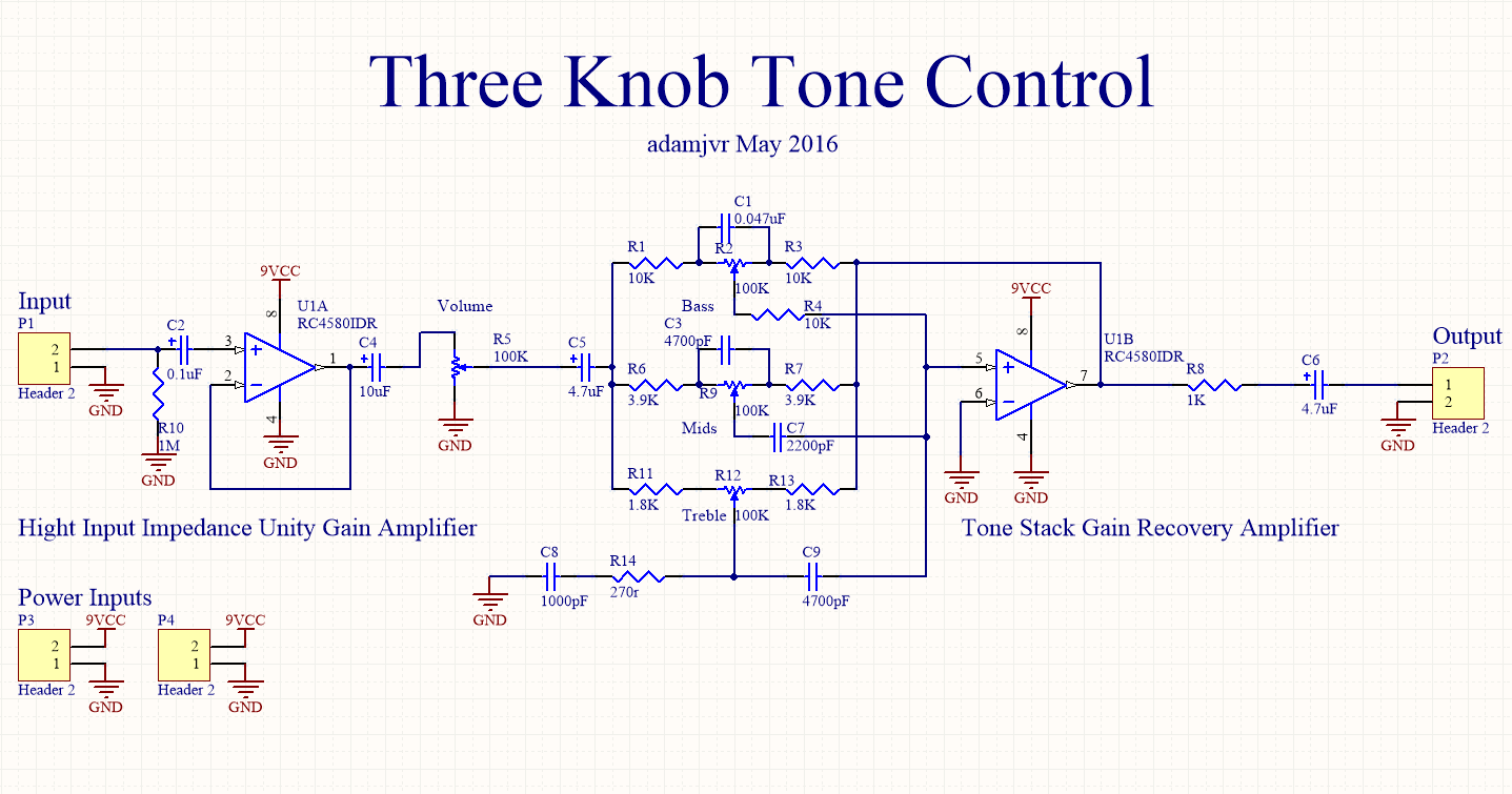
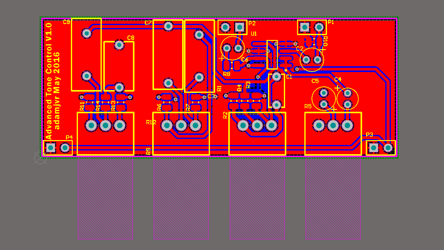
05/14/2016 at 19:02 • 0 commentsHey so since the last post I switched it up and did the custom tone control/tonestack I mentioned in the details section of the project page. So this tone control circuit is copied from the one I found on this page http://www.eleccircuit.com/three-circuits-of-preamp-tone-controls-by-ne5532/ . The tone control on that page appears to have been pulled from a solidstate stereo amplifier. The full schematic included Treb/Mid/Bass control for two channels with a volume/balance control between the two. The design I made extracts the tone control section, includes the input volume, and adds a unity gain input amplifier to the circuit. Below is the schematic:
![]()
The schemtic went pretty quick, though finding all the appropriate components took quite a while. So this is the first pass on routing it, I'm still thinking about it incase anything additional comes to mind. I also need to adjust the input pin spacing to make it breadboard compatible. Anyways this design should be finished soon and off to the fab shortly. I haven't stated before but I will be using OSHPark for my PCB fab and possibly doing a lot of these boards as 2OZ copper boards, they are fast and quality for the cash. Below is the first PCB routing pass:
![]()
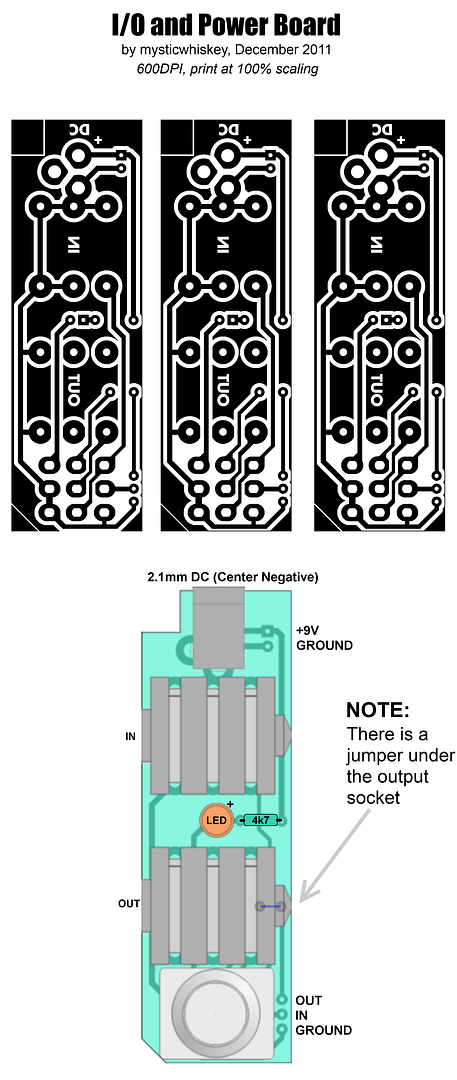
So the new project is a small mini one and its not even my idea, its just a really great idea/design that I found years ago. Its a guitar FX pedal power, input, output, wiring PCB that makes building and wiring custom analog guitar FX pedals easy. The user that originated the idea is mysticwhiskey on the madbean pedal forums, http://www.madbeanpedals.com/forum/index.php?topic=3308.0 . He used that design in his custom delay pedal build, I have been planning to make my own version of the PCB so I can have a bunch on hand for future builds, now is the time. Here is mystic whiskey;s design:
![]()
My design will be basically the same, he'll be credited on the PCB too ;), the only differences will be my component choices for the jacks, switches and other components. Stay tuned for more to come!! -
DT JFET Preamp
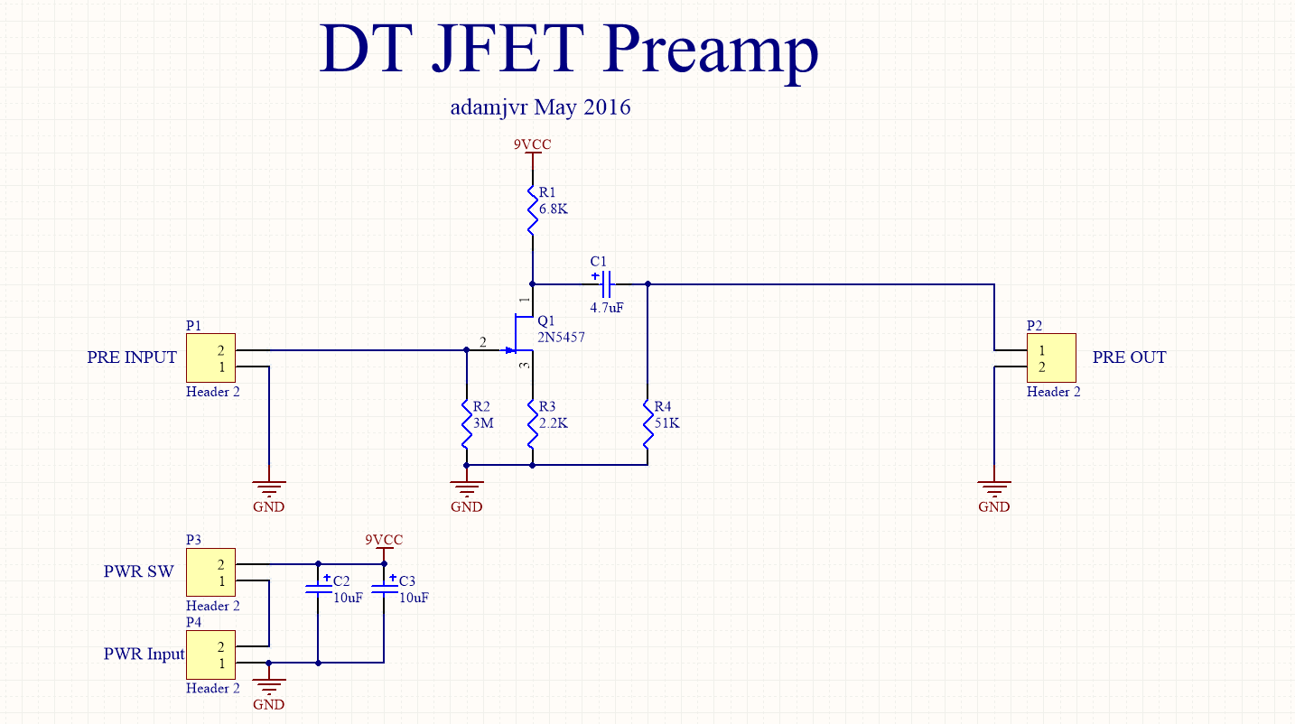
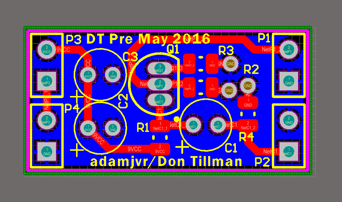
05/11/2016 at 22:55 • 11 commentsSO got another one for you guys today! The infamous Don Tillman JFET preamp is a design that has been kicking around the web since the early 2000s. I recall seeing it all over DIY guitar effects forums back in the day and even did a old design in eagle a few years ago but never fabricated it. Anyways I wanted to finally make a board and give it a shot, so here is my schematic and PCB:
![]()
First Route of the PCB:
![]()
All credit goes to Don Tillman for designing this preamp, I merely just copied the schematic to make this snazzy PCB. Check out his original page here: http://www.till.com/articles/GuitarPreamp/
Stay tuned for more folks!
-
Let's Get Started: Big Muff Blox
05/11/2016 at 16:45 • 0 commentsSo before engineering/hackaday-culture became my life music was my main hobby playing guitar, drums, bass, and singing, in that order ;) I collected a lot of guitar equipment over the years but one of if not the most defining piece of gear I have is my Electro Harmonix Big Muff Pi fuzz pedal. I got this pedal because of my diehard fandom for The White Stripes and wanting to make music like that. Throughout my shortlived musical experience playing in bands in high school the Big Muff was at the centerpiece of my sound. With all that said, back to the engineering!
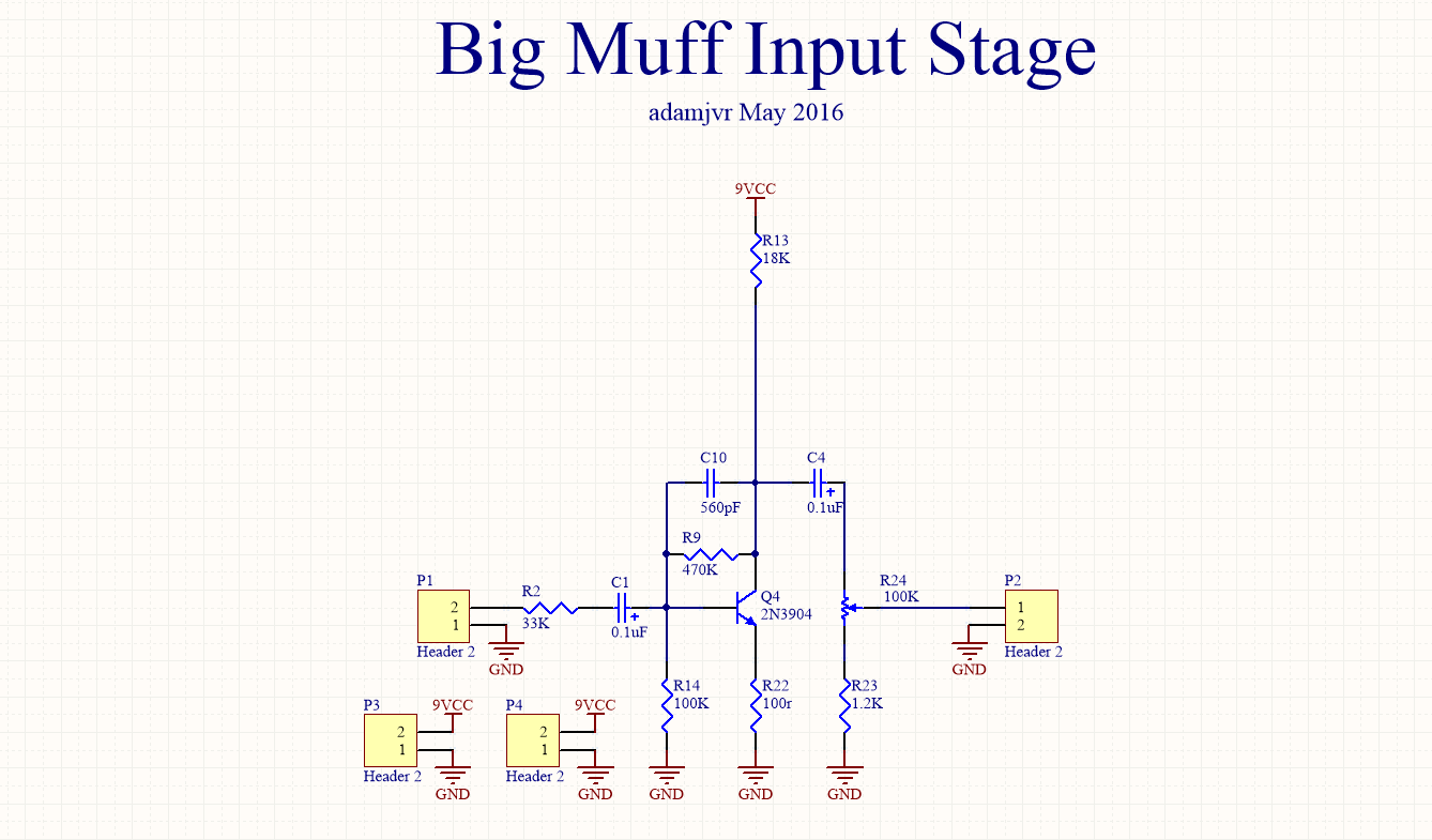
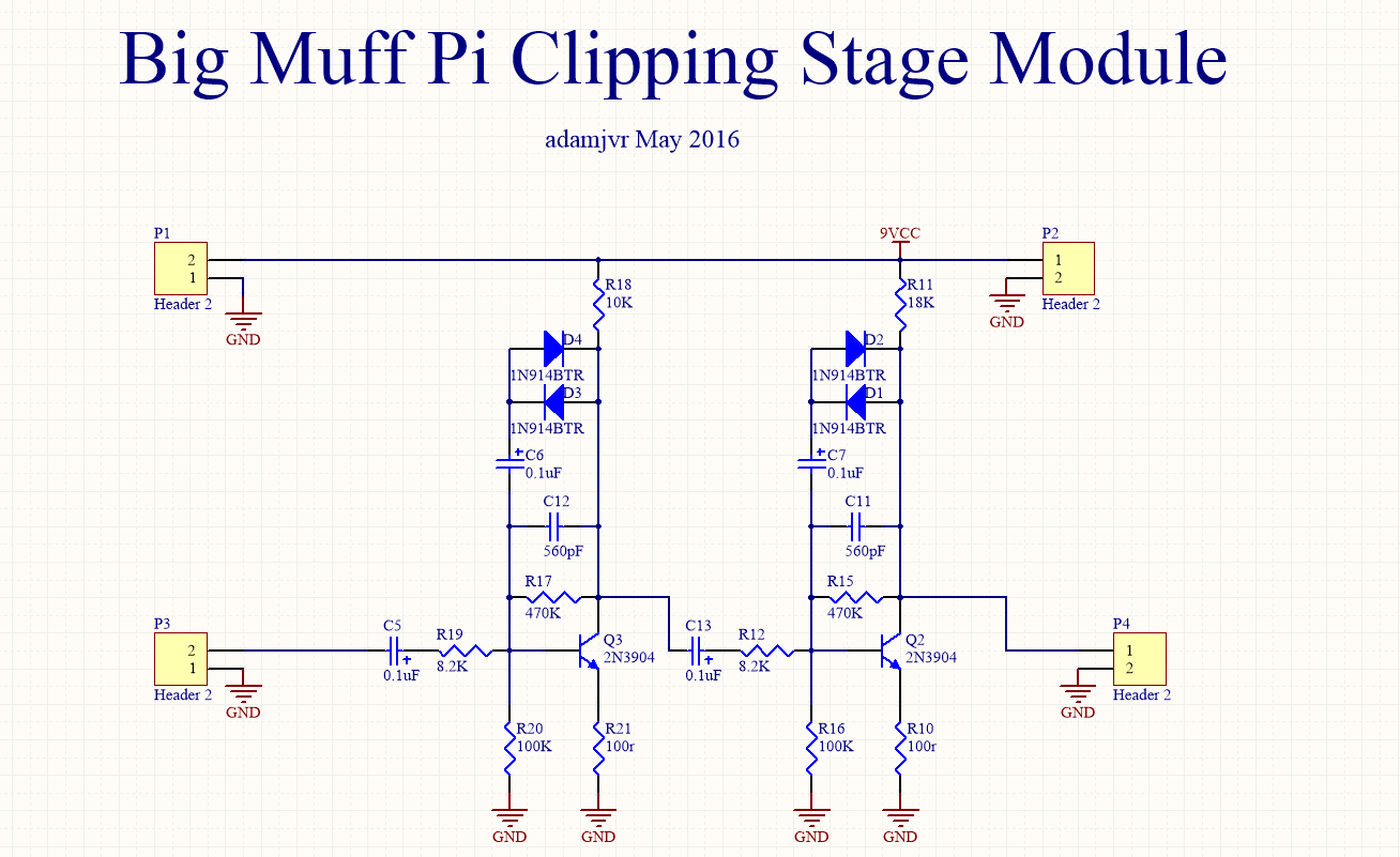
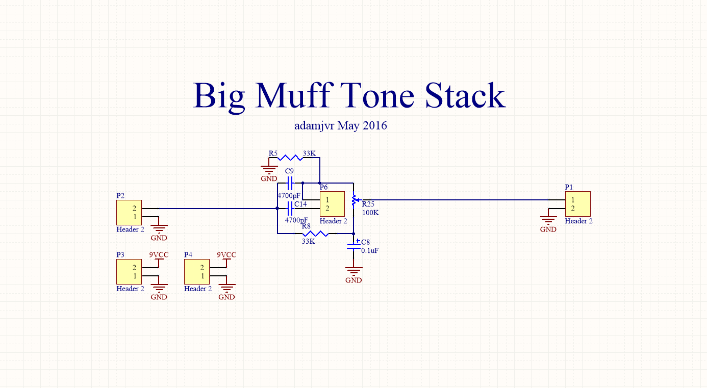
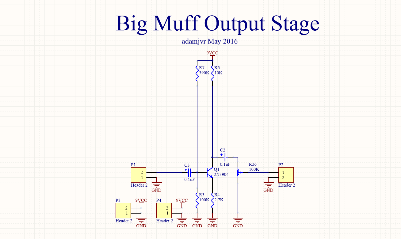
So this initial project is what I call Big Muff Blox, unlike my PiModulos project which aims to be a general purpose Big Muff clone PCB this project is designed for experimenting and understanding the different stages in the Big Muff circuit. Big Muff Blox will be a collection of PCBs that contain each of the Big Muff fuzz stages like so:
- Input Stage
- Clipping Stages (both on one PCB)
- Tone Stack
- Output Stage
So in short Big Muff Blox will be 4 PCBs deividing the Big Muff pedal circuitry across four PCBs. The PCBs will be design to plug into a breadboard for testing, experimenting, and analysis. With that I give you preliminary schematics for each of the boards:
Input Stage Schematic
![]()
Clipping Stages Schematic
![]()
Tone Stack Schematic
![]()
Output Stage Schematic
![]()
That's all for Big Muff Blox, expect more over the next days but expect something different maybe later today, stay tuned!
NOTE:
I wouldn't be able to do this project and other Big Muff realted projects if it wasn't for this amazing website, check it out, this guy has everything there is to know about this circuit !
http://www.kitrae.net/music/music_big_muff.html
Circuit broken down and explained here:
Audio Blox: Experiments in Analog Audio Design
A Project page to host and blog about my various analog audio circuit experiments and designs.
 AVR
AVR