Since the Diode Clock is fairly large and complicated, I wanted a smaller example to demonstrate how simple diode logic gates really are. The result was the DDL demo board (shared here on OSH Park). The design files (Eagle schematic and board files as well as LTspice simulation file) are shared here on hackaday.io. I've included decent models for the 74AC14 used in the power supply, and of course, for the 1N4007 diode, so the whole circuit can be simulated in LTspice. If you're willing to wait for it.
The board looks like this:
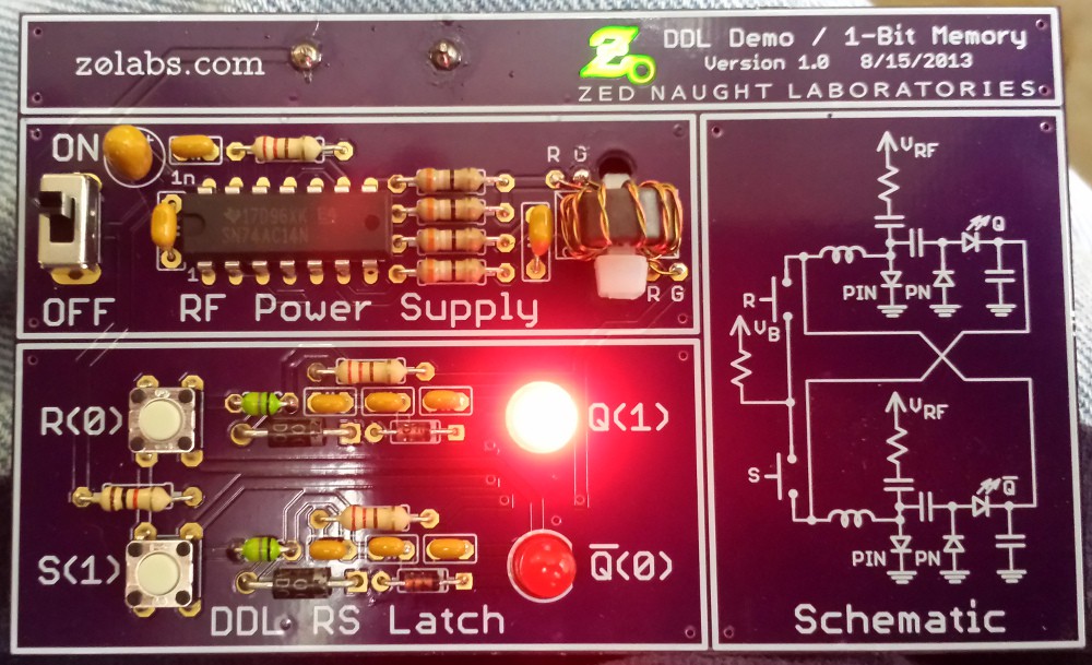
This perfect purple board was (obviously) fabbed at OSH Park; Laen wrote somewhere about people drawing schematics on the silkscreen layers of their boards - when I read that, I knew it was exactly what I wanted. The idea is to have a pocket-sized demonstration of the simplest diode-based logic circuit you can't build with "traditional" diode logic (AND and OR gates). It's an RS flip-flop that stores its state in six diodes: two 1N4148's, two 1N4007's, and two red LEDs, which double as indicators. With four AA batteries on the back, it can store a single bit of your choice for as long as the batteries last (~48H - it's a power hog). A more complex version of this circuit was what convinced me in 2008 that universal diode-only logic was possible. I think this is probably as simple as you can make it.
Here's a silent film of it in "action":
Now, what's the coolest information you can store in a single bit?
The latch circuit
Here's the latch circuit schematic:
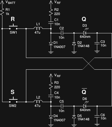
The top portion associated with D1 and the bottom associated with D4 form two inverters. When DC current flows through D1, it shunts the RF current through R2 to ground, producing no output through D3. meanwhile, the lack of DC current through D4 results in a high impedance to ground for RF, which energizes the voltage doubler consisting of D5/D6, closing the feedback loop, and maintaining the current state. If you then press SW2, D4 starts to conduct, and the roles reverse, storing the opposite state. More info can be found in the datasheet.
The LEDs deserve some special attention. I specifically used 640nm LEDs (Kingbright WP7113SRD/E @ Digi-Key) because of their high brightness and low Vf (1.85V @ 20mA). Both really help in not overly loading DDL outputs. If you can afford them, the /F or /G grades of that part are even brighter - every little bit helps. I've also tried fairly random LEDs, and found the results to be hit or miss. This morning, I breadboarded a version of this circuit with some junk-bin green LEDs and a simpler power supply but had to turn off the shop lights to see that it was working (see below).
DDL Power Supplies
The RF power requirements of DDL logic gates are the most difficult aspect of these bizarre circuits. The DDL02 power supply board took seven fairly major iterations to get "electrically right", and it probably could use an eighth for thermal issues. I'll be documenting those tribulations shortly. Even simple DDL circuits like the demo board can be fairly picky about the RF supply. Here's the supply on the demo board:
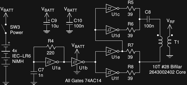
In a somewhat perverse twist, I'm using a 74AC14 hex Schmitt-trigger inverter as a power supply for the diode logic circuit. An RC relaxation oscillator made with one gate (U1a) drives a buffer stage (U1b) before a push-pull stage (U1c - U1f) AC coupled to a broadband transformer to generate the required RF supply for the DDL circuit. The 74AC series is plenty fast, the outputs can source or sink 24mA with symmetrical output impedance, and it has edge rates near a nanosecond. They're some of my favorite analog parts. Don't substitute an 74HC14 or TTL part here; they won't drive enough current. This supply runs at about 3.6 MHz, depending on component tolerances and temperature/
I wound the transformer on a Fair-Rite 2643002402 core, because I have a large bag of them. It's intended for EMI shielding, but it's just a core of 43-type material that's really cheap, and makes great broadband transformers. An alternative is the Laird 35T0501-10H @ Digi-Key, which will work just as well. Any core designed for use at HF, like the Amateur-radio favorite FT37-43, would also work.
Alternative Supply
I realize that not everyone will have a 74AC14 lying around, so I breadboaded another simple supply and latch this morning using a 6MHz oscillator can from the junk bin:
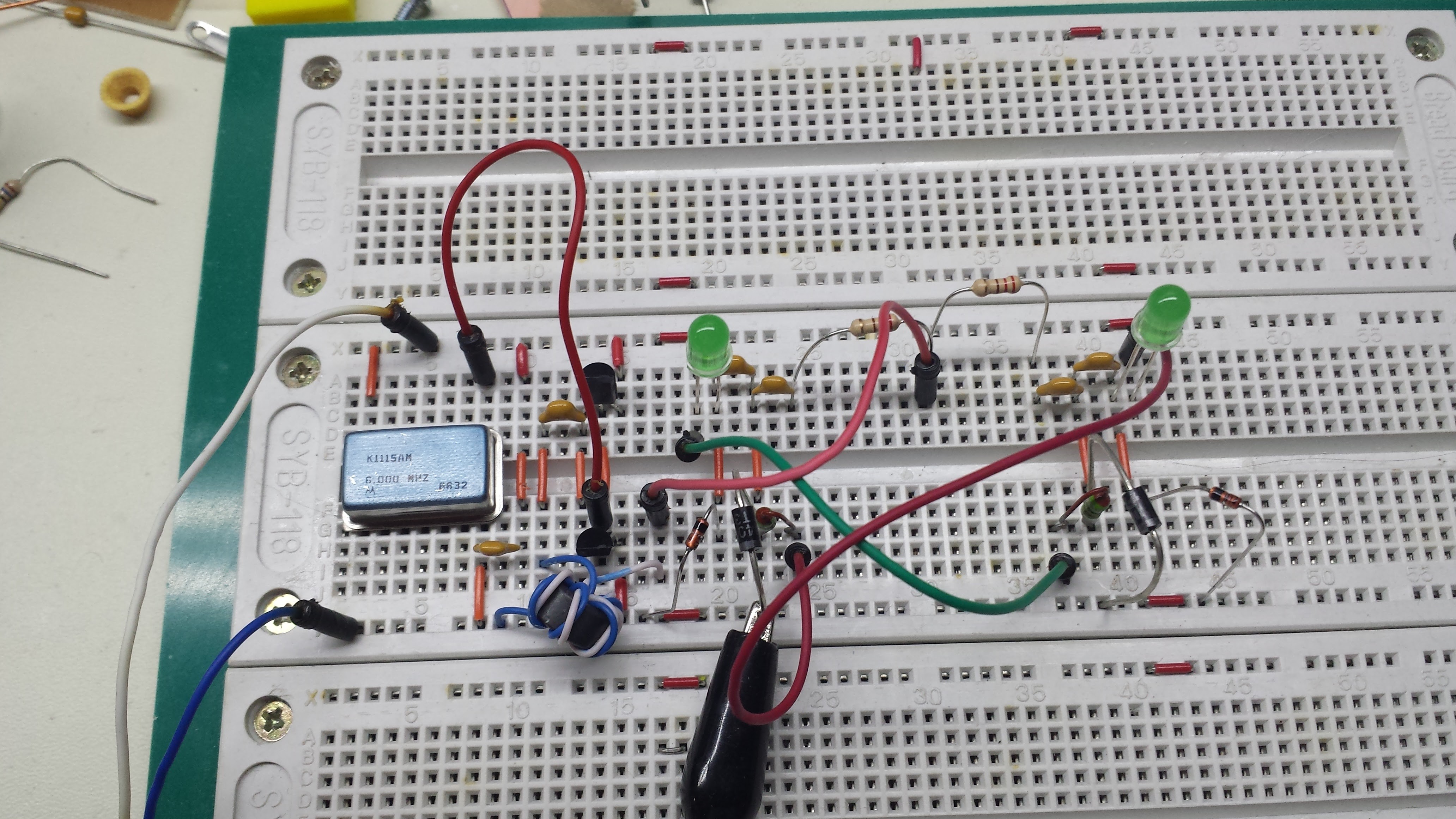
The latch is identical to that described above, except for the use of "random" standard-brightness green LEDs. The power supply looks like this:
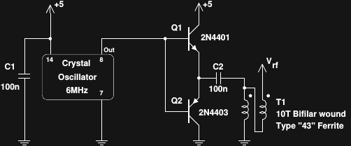
Q1 and Q2 are wired as emitter followers to boost the current output from the oscillator (and we accept the 1.4V of lost voltage swing). Any complementary pair should work here (2N3904/2N3906 or 2N2222/2N2907 come to mind). C2 blocks the 2.5V DC component of the output to avoid loading Q1 excessively. Finally, T1 is wired as an auto-transformer to boost the RF voltage by a factor of two. This circuit would probably work with oscillators from 3 to maybe 10 MHz. I briefly thought of using the internal RC oscillator / clock output option of a 4MHz PIC microcontroller (with no code running) to drive the transistors, but figured the oscillator can was (slightly) easier. For the transformer, I didn't feel like twisting up a pair from magnet wire, so I just used a section of twisted pair from a CAT5 cable. I could only fit about 5 turns on there, but it still works well enough for a quick demonstration.
Between the thrown-together power supply, the lousy green LEDs, and maybe parasitic qualities of the breadboard, the performance isn't great. I had to turn off the shop lights to see it, but it does still work as a latch:
 Ted Yapo
Discussions
Become a Hackaday.io Member
Create an account to leave a comment. Already have an account? Log In.
The LED you use is a little expensive. I wonder if there are any alternatives.
Are you sure? yes | no
Be sure to test any others before buying a bunch. That particular LED was chosen for low Vf and high brightness at low currents. You may be disappointed by ordinary ones.
Are you sure? yes | no
I might just give this a try. I wonder if my 80m qrp osc will work for the power end for the demo circuit. I like this :-)
Are you sure? yes | no
Give it a shot! You might need a matching transformer at the output or something like that, but I wouldn't be surprised at all if it just worked. I originally used a 6 MHz oscillator for experiments because an "oscillator assortment" I ordered turned out to be 90% 6 MHz cans, and I had no good use for them otherwise :-) It doesn't seem to matter that much.
Are you sure? yes | no
Build it on those shiny brass nubs !
:-)
Are you sure? yes | no
You got it :-)
Are you sure? yes | no
[this comment has been deleted]
That's just the demo board :-)
The clock itself uses four power supplies, each capable of producing 35W at HF. Added up, that's more than my IC-7200 does!
I spent a lot of design time on a spread-spectrum exciter in an effort to
push emissions into the noise floor, and phased the four supplies to
minimize far-field radiation, but haven't done rigorous tests on how
well it works yet. I'll tackle that when I document the power supplies
and exciter (coming soon). I don't think I've ever had it running when
the bands were open, and simple tests with a portable HF receiver didn't
indicate much trouble.
Now I have to go check my front door for angry hams...
Are you sure? yes | no