Project Rockoon
Actively stabilized model rocket by means of a motor gimbal, originally designed for launching a rocket from a high-altitude weather balloon
Actively stabilized model rocket by means of a motor gimbal, originally designed for launching a rocket from a high-altitude weather balloon
To make the experience fit your profile, pick a username and tell us what interests you.
We found and based on your interests.
I threw together this video for my resume. It summarizes the work I've done on this project so far, and I figured it would be a good addition to this hackaday page.
About a month ago I started a new semester, and I have not been working on this project much. I've made a decision to put this project on halt until I go back home for winter break.
I've also made a decision to shift the focus of this project to the gimbal for now. I would like to use the gimbal to fly an actively stabilized rocket and recover it.
Since coming back to school, I've joined some projects led by students more knowledgeable than I. I'd like to focus on these projects because I see more learning opportunity there and these projects have larger, more well defined end goals.
The goal of one project is to create a small scale liquid rocket engine. This engine won't be on a launch vehicle very soon, but for now we are trying to get a successful hot fire test.
The second project is looking to use a 2 staged, solid propellant rocket to break the Karman line and officially reach space.
Definitely excited about what's to come next.
I'd like to state again that Project Rockoon is not over, and progress will resume again at a later date this year.
I'd also like to leave a video of a successful, tethered stabilization test, so that anybody stumbling upond this page can see the progress so far.
Onwards and Upwards,
Julian
Today I conducted the 5th gimbal test with a live motor. This time I used an E engine, which has 4 times the impulse of the C engine used previously. I used a similar test configuration with a tethers on either side. I made some improvements to the rocket, most notably a method of precisely adjusting the positions of the solenoids. This allowed me to find a "sweet spot", where the permanent magnet in the solenoid that locked the slug in the extended position actually assisted in nudging the motor to one side. This was important because the E engine had significantly more mass. After adjusting the calibration screws on each solenoid, the mechanism was reliably angling the engine in all 4 possible directions.
Here's a clip of the test:
As seen in the video, there was a rapid unscheduled disassembly. The forces exerted by the tethers caused the gimbal/engine assembly to shear from the electronics/payload bay. The gimbal/engine assembly, still being propelled, flew off in another direction. I was able to recover most of the parts, but I was not able to find 2 out of the 4 solenoids. Some of the 3D printed parts also broke. The cost of replacing the solenoids will set me back about $10, so it is not the end of the world.
Unfortunately, this test was also not very productive. Despite adding additional dead weight to the rocket, he engine imparted so much speed off of the launch rod that I'm not even sure if the gimbal factored into stabilizing it. This fact, combined with the CATO, leads me to think that the only way to accurately test the gimbal mechanism with an E engine will be to fly an untethered rocket. This means developing some sort of recovery method.
I will be going back to school in 5 days, and that being said, I do not have sufficient time to rebuild the broken parts, develop and test a recovery method, and wait on a shipment of 2 more solenoids. I believe that this was the last test of the summer.
That being said, I will rebuild the parts that did break and bring what I have so far to school with me. With classes and shared resources, progress will certainly be slower. I may also discover another rocketry project at the club. With these factors, I may not continue work on this project until I come back for winter break. I will move in prepared for either option, and I will make my decision after learning more.
Also, I have one last E engine left. I may throw a simple model rocket together to end the summer with a launch, just for fun.
Today I conducted a test of the gimbal from a launch rod using extra long tethers. I was hoping that the launch rod would keep it straight during the initial thrust spike, and that the gimbal would take over from there. At the moment, there is no recovery method, or even a nose cone for that matter, so the tethers will keep the rocket from being destroyed.
Over the past week I've made some notable improvements. I've realized that the small differences in the tolerances of the solenoids meant that the engine was not being angled equally in all directions. I really wanted to calibrate the position of each solenoid with some sort of adjustment screw, but with a mechanism/rocket this small, there's really very little space for something like that. I ended up making a plate the sits behind the solenoids that has small elevated ridges for each solenoid to sit on. The ridges for each solenoid can be individually filed down so that the right height can be achieved. It only took about half an hour to calibrate this piece so that solenoids sat in the right position. I'm thinking that I could make a few of these plates to test different angles of deflection.
The code has remained unchanged for this test, but the test itself was changed quite a bit. I put a launch lug on the COM harness, and launched the rocket from a 3/16" x 3' steel rod mounted on top of a garbage can. I positioned tethers roughly 4 feet out and 8 feet up (from the ground). One tether was attached to the top of a ladder, and the other was wrapped around the trunk of a tree. The plan was to pull out the trash can with a rope when the rocket left the launch rod, so that as the rocket swung back down, it wouldn't hit the launch rod or the ground. If the gimbal sent the rocket in a wild trajectory, it would still come out unscathed.
Here's a clip of the test:
Overall, I couldn't be happier with this test. It looks like the rocket started tumbling when the tethers tensed up at the end. I had some bungee cords inline, so I was hoping to minimize this, but I guess it still imparted quite a bit of shock. Regardless, Everything before that went well. In the video, you can even see the gimbal making small corrections. Super cool to watch!
This test was done with a tiny C motor, so the next step will be to do some static engine tests with an E motor, and start working on developing a recovery mechanism. After that, a test will be done with an untethered rocket with fins, with subsequent tests using smaller and smaller fins. In order to go totally finless, I will either have to make or buy a motor with a thrust profile that would produce a small amount of thrust for stabilization through the coast phase.
Today I've conducted a 3rd test of the gimbal, and the 2nd test using the stationary COM harness. I've tweaked the code a bit by increasing the refresh rate of the gyro readings and decreasing the activation angle. I've redesigned the engine mount/gimbal a bit, so that the spring that provides the restorative force pulls the engine mount into the rest of the mechanism rather than pushing it into a flat. This mechanism is more reliable because it keeps the engine much more square with the rest of the rocket. It also means that the spring does not compress when the engine burns, which means that the geometry of the gimbal is the same whether the engine is burning or not, or if an engine with different thrust is being used. Looking back, the fact that the geometry changed at all was a poor design choice. I'm glad I noticed this because I think it made a big difference. I've also lubricated the ball joint that the engine mount sits in.
In making these improvements, I had to deal with some technical setbacks with repairing the 3D printer. I was having some issues getting reliable prints, and I ended up killing a whole day cleaning and calibrating. I also printed an improved fan duct, which helped a lot. I've decided to print everything with a brim now, as I've noticed that slight curling of edges was screwing with alignment of some crucial parts, including the engine mount.
Here's a clip of the test today:
Definitely the best test so far. I think that the initial rotation was caused by the initial spike of thrust of the engine. It did a pretty good job correcting, but I'm not sure why it took so long for the gimbal to pivot the engine. As it spun back to being neutral it did a beautiful job of angling the engine in the opposite direction to negate the spin. The maneuver was so quick that I only noticed it by watching the frame-by-frame.
Overall, I was really happy with this test. Not perfect, but good progress. I'm still having some issues where each solenoid is angling the engine different amounts. I believe this is due to tolerances on the solenoids and on the 3D printed parts. I will try to incorporate some way to calibrate the height of each solenoid.
I'm not too concerned about the initial rotation, because a launch rod could be used to keep the rocket straight for the initial thrust spike. I think the next test should be from a launch rod with longer, mobile tethers, but with the same COM harness.
After talking to some people, including Arsenio (from Hackaday) Joe (who's working on the Scout rocket), Mike (from Hackaday), and friends Owen, Adam, Erica, and Evie, I've designed a list of tests in increasing difficulty for the gimbal.
1. Pivot point placed about the COM, with a stationary pivot.
2. Pivot point placed about the COM, with extra-long paracord tethers.
3. Finned rocket
4. Finned rockets with gradually decreasing fin size.
Testing in this way should ideally help to isolate the gimbal and its stages of development, as well as reduce the chances of a rapid unscheduled disassembly.
Taking after Arsenio's advice, I designed a harness that can be adjusted to be placed about the rocket's COM. Skateboard bearings can be press fit into each side, and a screw and nut are used to secure it once it's in the best position
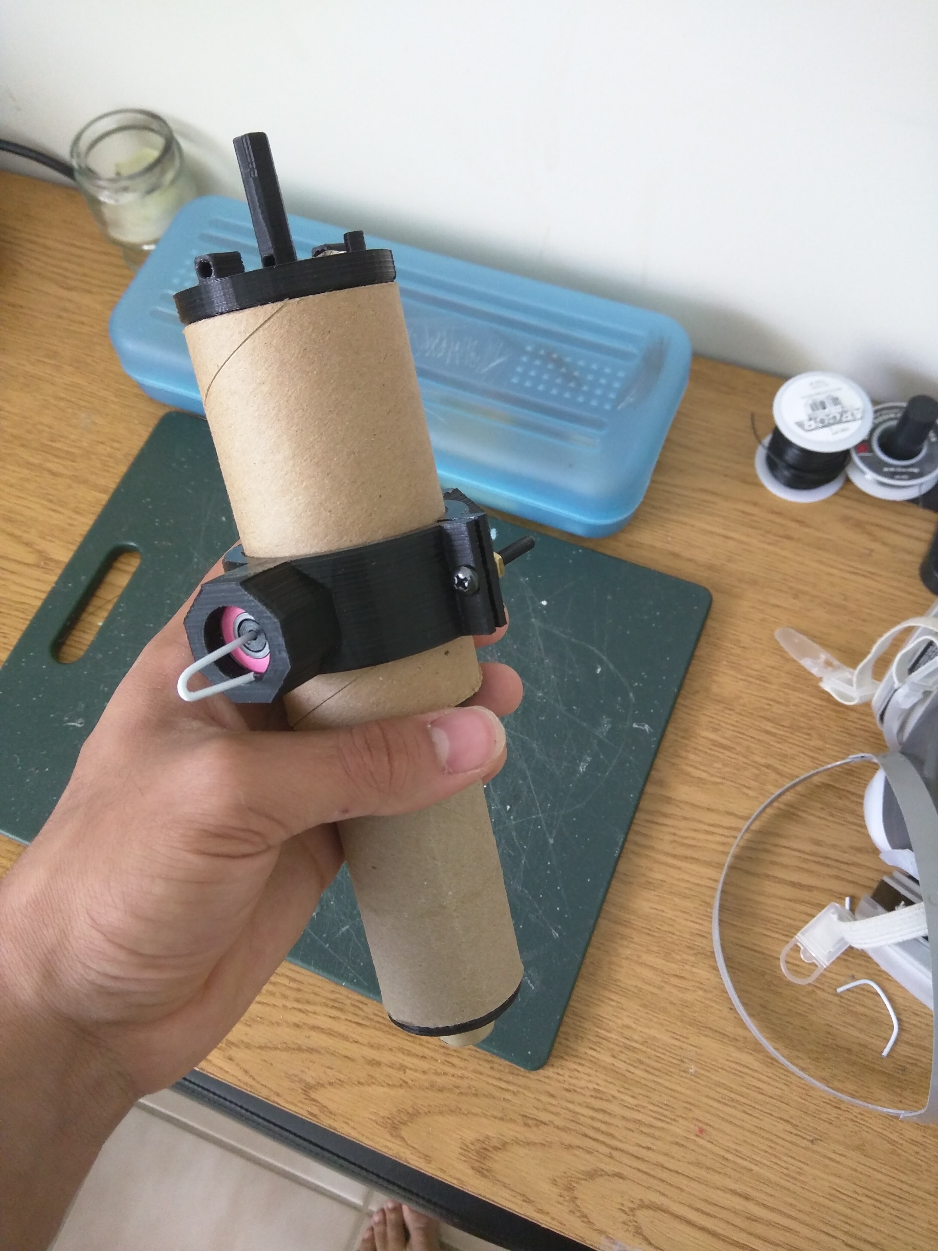
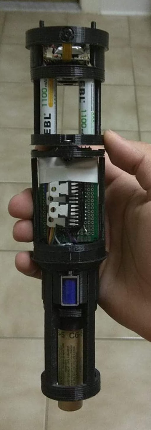
I've also taken the liberty to redesign some of the internals, as assembling and disassembling the rocket was sometimes cumbersome. There was also a pretty big problem where the gyro could easily be offset from the gimbal. In this redesign, I also added a camera compartment just for fun. It's not really needed at this stage of development, but its definitely interesting.
Here's the naked rocket in its current form.
I've conducted a second gimbal test, using the stationary pivot about the COM. Here's a clip of that:
Looking at the slo-mo, it seems like the gimbal wobbles during the peak thrust phase, and in doing so, the rocket stays pretty straight. It then goes into a spin that it can't correct.
Arsenio pointed out that it's possible that a spin was induced during the end of the peak thrust, and that the lesser thrust of the engine afterwards wasn't high enough (at the angle used) to correct the induced spin.
I'm currently thinking that are a few ways this specific problem could be fixed:
1. Variable angle (with servos or by varying the voltage that goes to the solenoids)
2. Constant thrust engine (expensive)
3. Launching with a launch rod (The rod would keep the rocket straight through the peak thrust phase)
Another weird thing happened with the code. Why was the engine wobbling at all at that angle? It should've been wobbling when it was straight up and down. Maybe a calibration issue?
After looking at the 3D printed parts closer, it seems that a slight warp meant that the gimbal was not tilting equally in all directions.
Also, a slight irregularity in the ground end of the spring I'm using means that the rest angle of the engine is not perfectly square with the rest of the rocket. At first, I thought this was so subtle to not effect anything, but it might be worth looking in to.
I finished up my gimbal testing rig by adding a battery holder to the top. It'll hold 4 rechargeable AAA batteries, supplying just a little over the 5V needed (rechargeable AAA's typically supply between 1.2-1.3V). Rechargeable batteries are important, because eventually they will be used to deploy the parachute. Because of that, I'll definitely want to top them off them before every launch. I left room in the middle of the batteries so I could eventually put hand warmers in order to keep them running at the low temperatures of the stratosphere, as J. Hopkins pointed out. They won't be needed for this test, but I've learned in this project that thinking ahead a few steps can usually save a good amount of time.
There's a piece of bent coat hanger running through the middle. I bent it ahead of time and stuck it in there as the part was printing. It rotates quite nicely. Eventually this battery holder will become the nose cone.
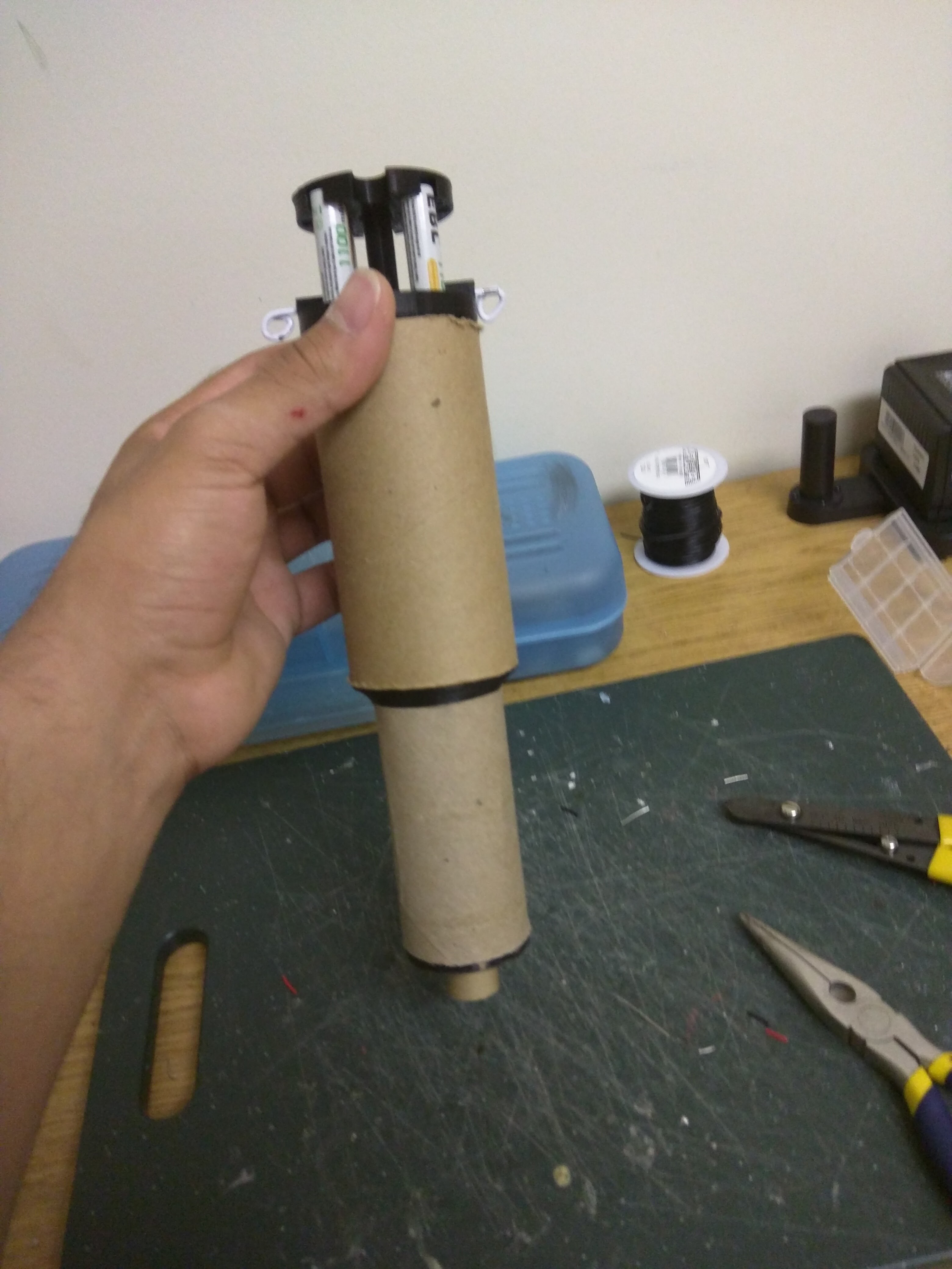
For anybody new following this project, I'm currently focusing on stabilizing a rocket with thrust vectoring, by tilting the engine using a gimbal. It should eventually look something like this.

I finished up the this iteration of the arduino code. Here's a clip of the gimbal actuating in reaction to the tilt of the rocket.
I also conducted the first tethered test of the gimbal with a live motor tonight! Here's a clip of that:
I went into this test not expecting it to work. In fact, it would have been a miracle if it did. My main goal was to learn more about the behavior of the gimbal in its current state. With that goal, it was a success.
Looking at the slo-mo, it seems like the rocket reacted quite badly to the initial yank of the rope after the engine ignited. It almost tilted to a full right angle. It corrected itself after that, but I'm not sure how much of that might have been due to gravity. It swung to the right, and again corrected itself. It swung to the left, and again corrected itself. There seems to be a pattern here. It's oscilating back and forth, with an increasing amplitude each time. In the next oscillation, it toppled over itself, but as it swung back to the starting position, it corrected itself quite nicely. It swung to the left, corrected itself, and then did a full circle again before the engine burnt out.
Overall, I was really happy with this test. My intuition tells me that the gimbal is severely over correcting.
I think that there are probably 5 ways (or combos of these ways) to fix this:
1) Decrease the angle of activation the gyro must read before the gimbal activates.
2) Decrease the angle that the gimbal tilts the motor
3) Increase the refresh rate of the gyro (right now, its at 10ms)
4) Use some clever programming that would figure out how to tilt the motor to correct instability, and then tilt in the opposite direction to stop any spin caused by the correction as the rocket straightens out.
I'm not very knowledgeable or experienced in analyzing something like this, and I'm basing these conclusions off of intuition. Any recommendations or advice on to how to tackle this problem would be much appreciated.
I'm working on creating a test rig for the solenoid gimbal so that I can calibrate the program before putting it on an unrestrained rocket. First I had to consolidate all the electronics onto a perf board.
I started with this rat's nest:
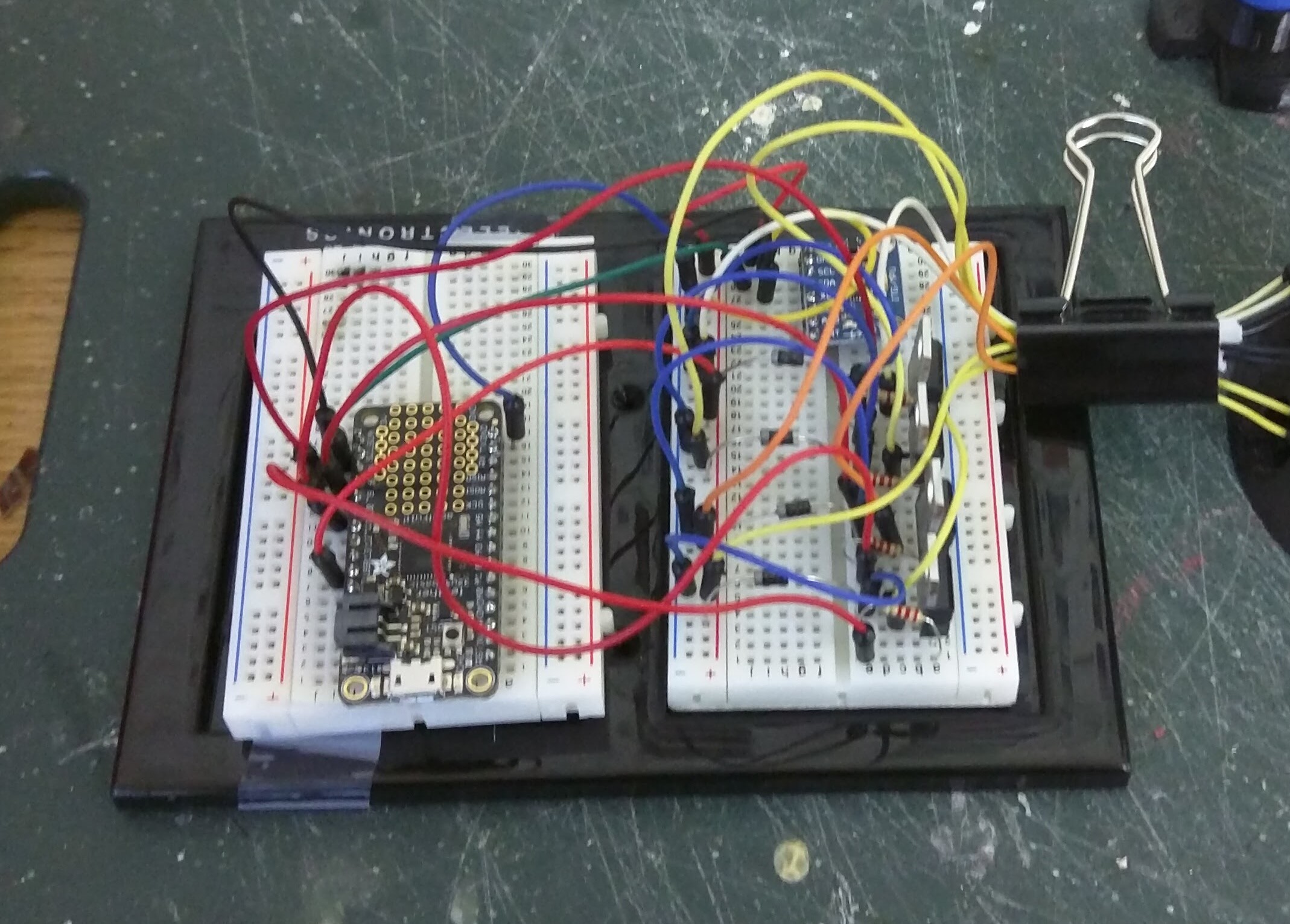
And ended with this:
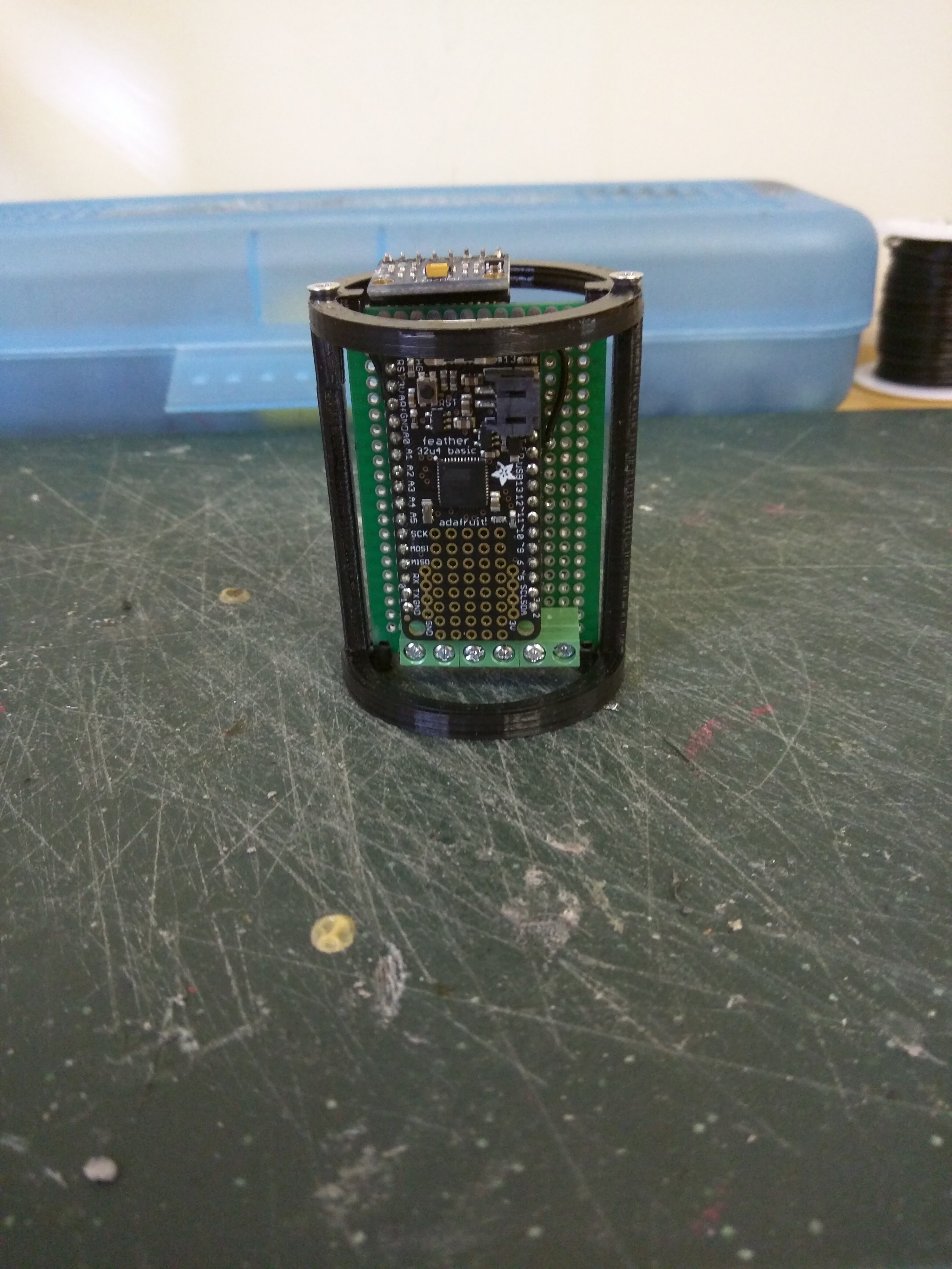
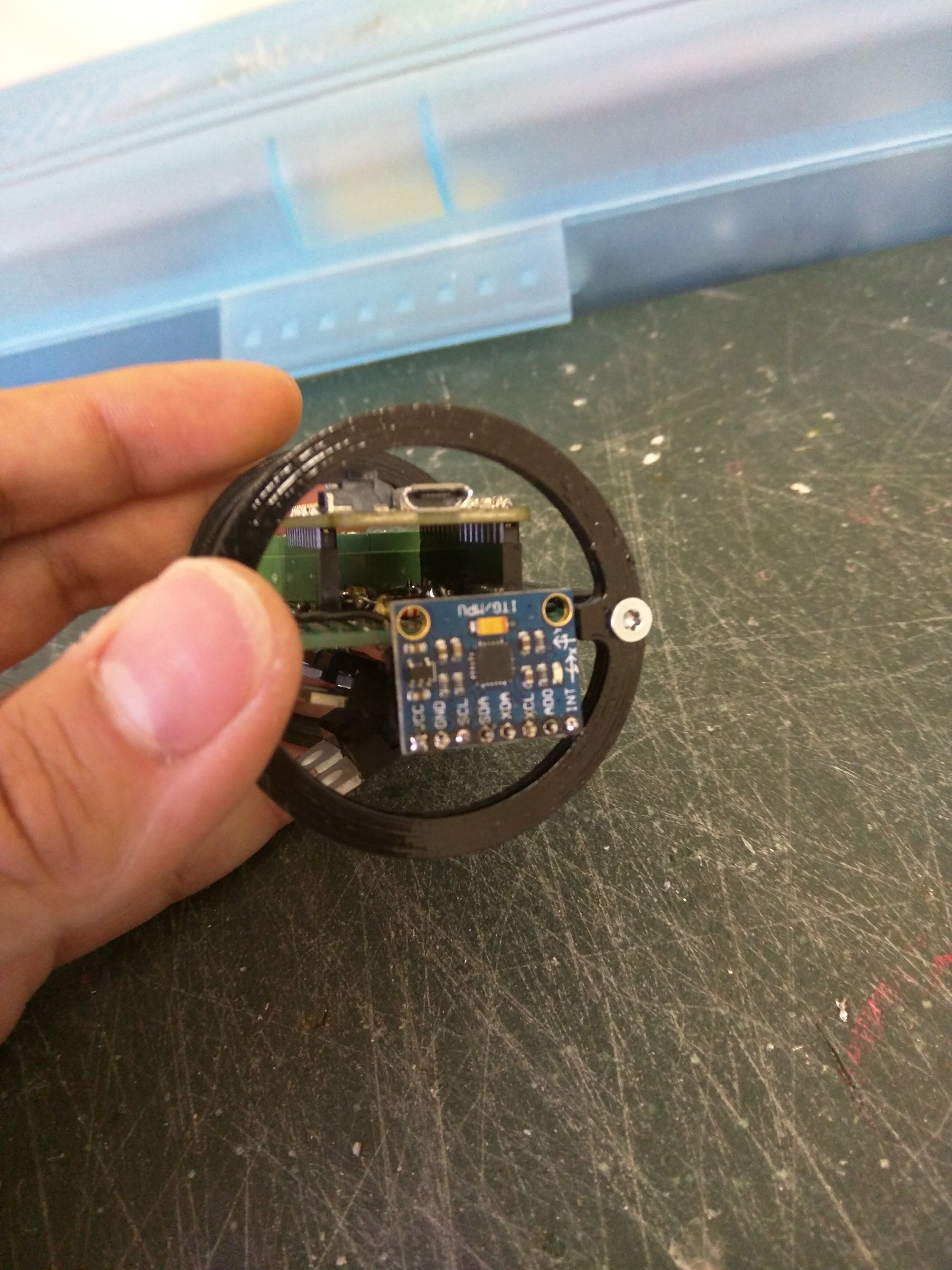
I fixed this to the gimbal with a transitional piece and some screws:
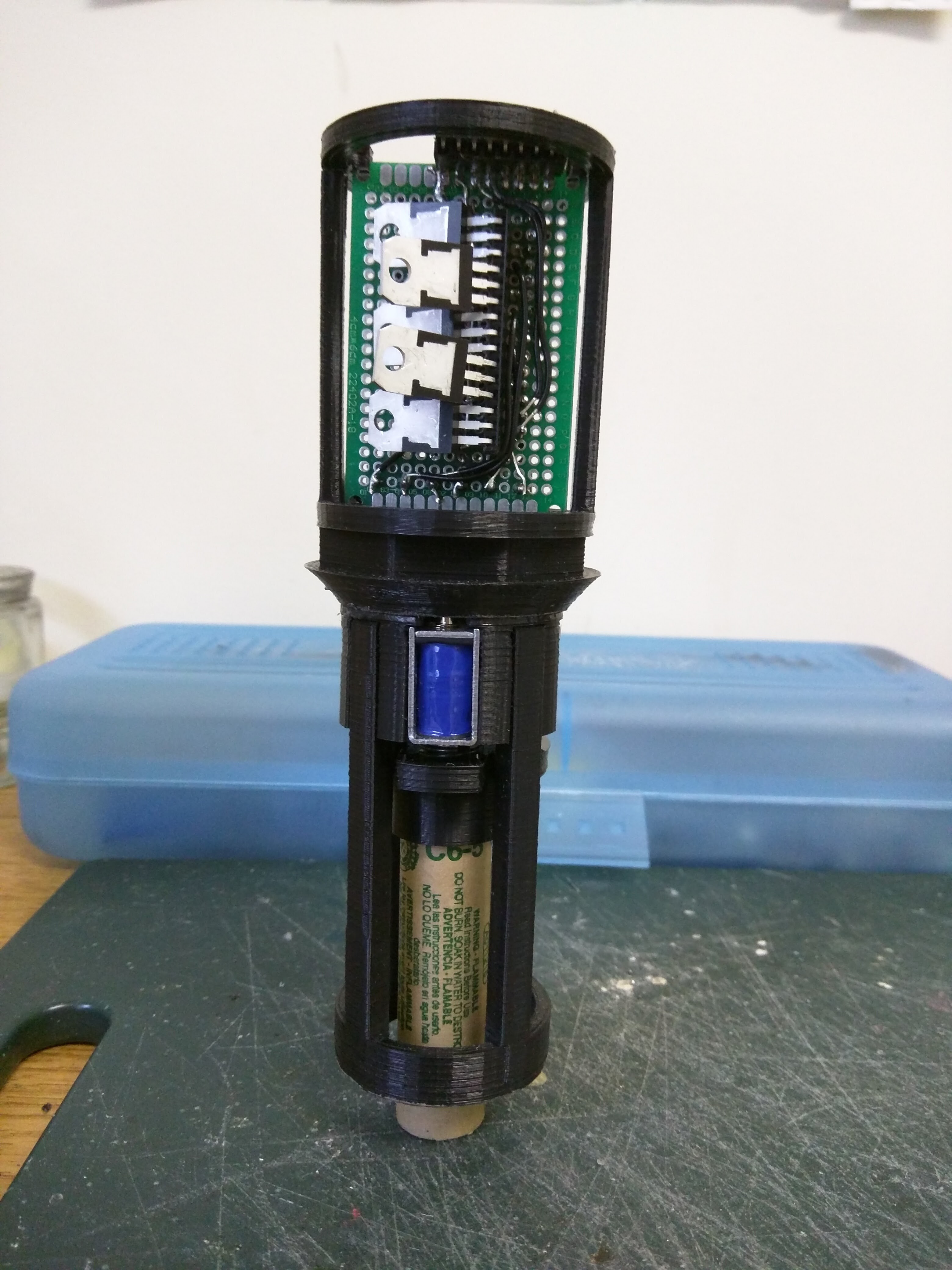
And I covered it with a shipping tube and a paper towel tube that I found:
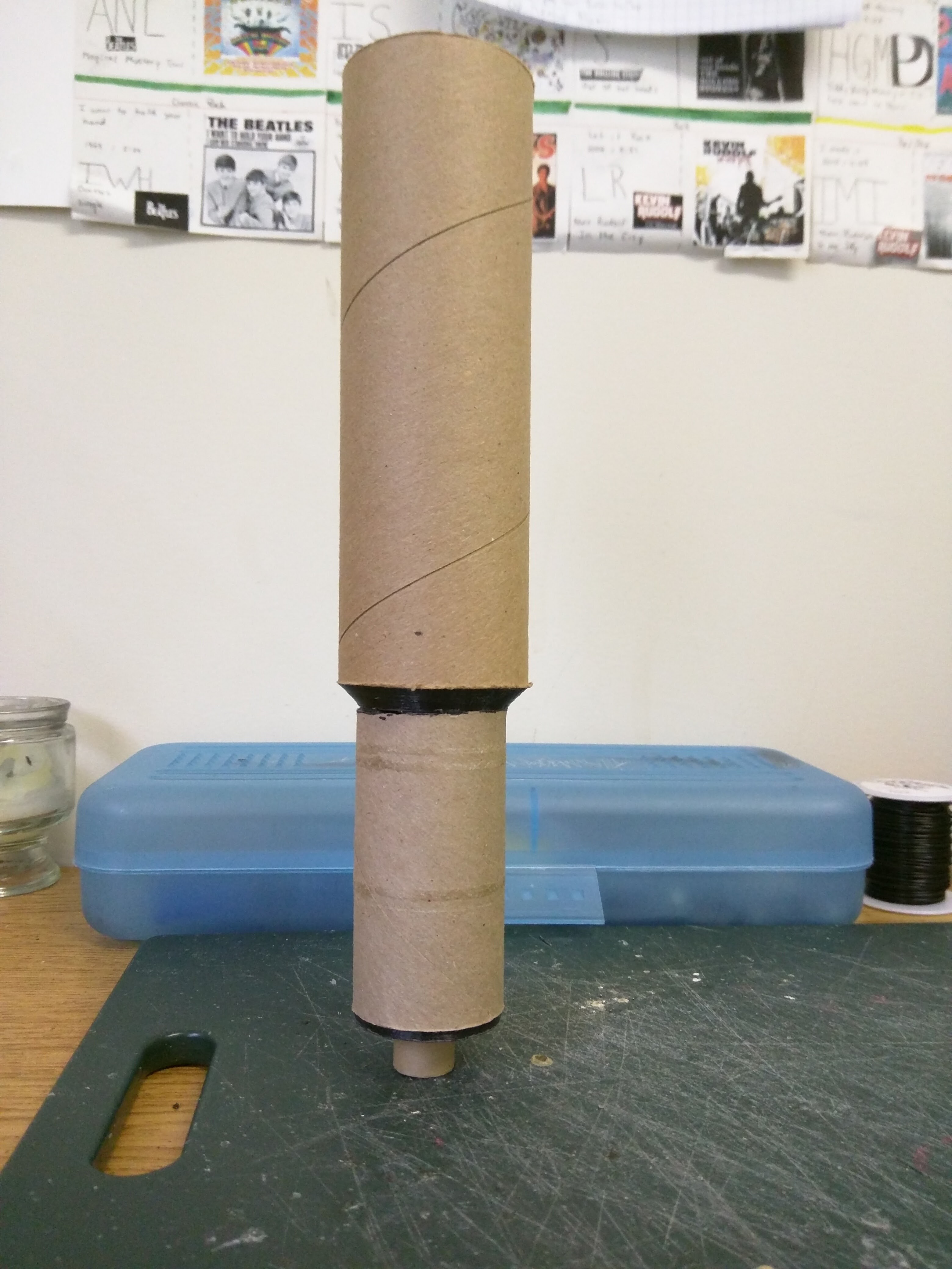
Now I just have to add batteries and a way to suspend/restrain it, and I should be ready for the first test.
Adding in the mass of the batteries, the whole thing is almost 275g, weighing in at about 2.7 newtons.
This is a little more than double the recommended take off weight for this size engine.
However, looking at the time-thrust curve for the Estes C6 Engine, I should still have positive lift for the duration of the engine burn. It's not a huge amount, and won't be suitable for an actual flight. I'll definitely wanna go for a D, E, F, or even a G engine when I fly this unrestrained. But for testing purposes, it should be enough to help calibrate the gimbal.
I've been working on improving the solenoid gimbal, and I've made some exciting improvements. I moved the spring to be behind the engine instead of being surrounding the engine. This means I can use a smaller, lighter spring, and it also means there is more space around the engine. This will allow me to use 24mm engines, opening up the possibility of using D, E, and even some F engines. I'm still looking to see if I can use a 29mm G size engine. This would increase the total possible impulse of the rocket by a factor of 16. Definitely significant.
Here is a picture of the improved mechanism, stripped down to the functional parts
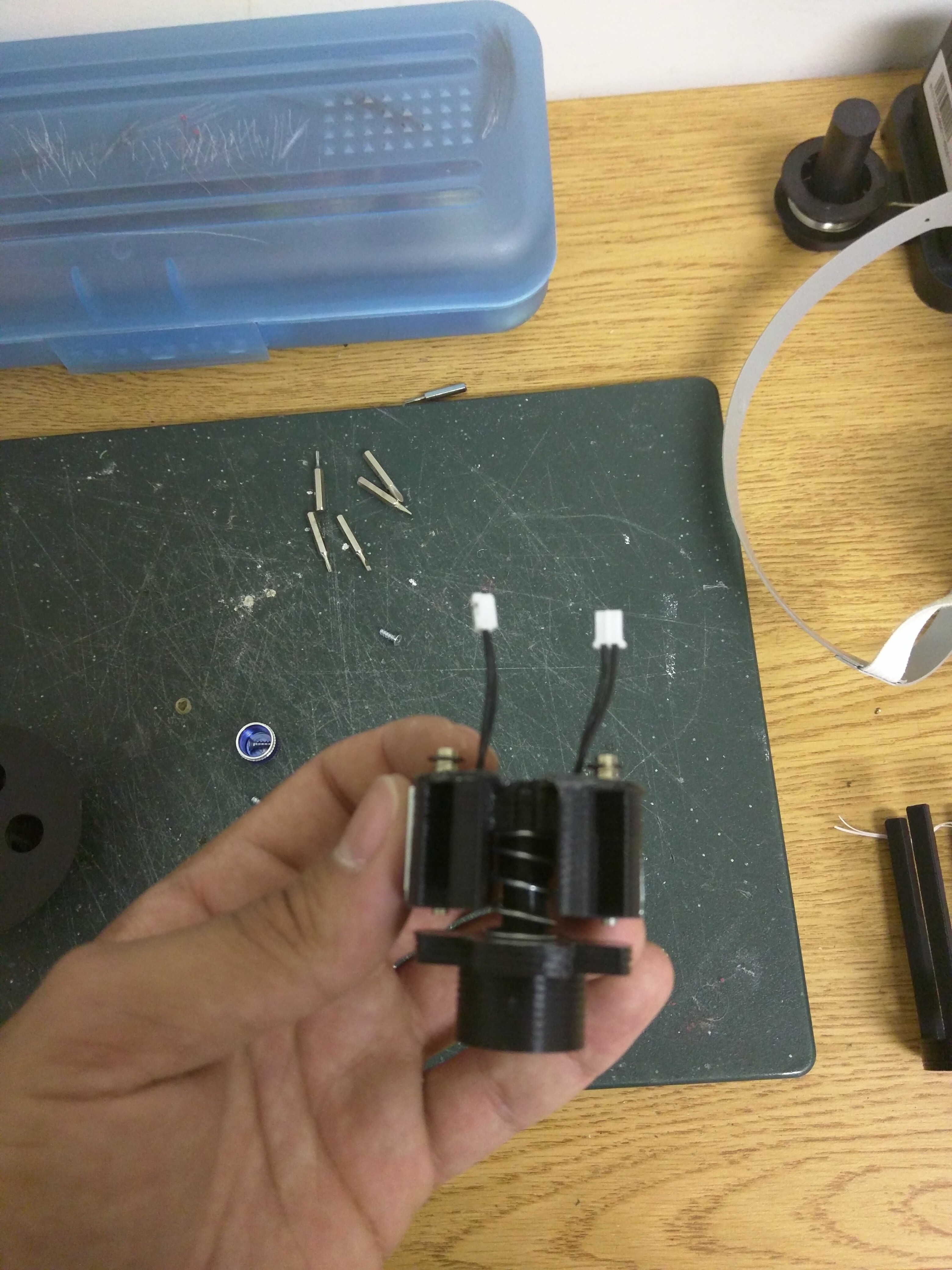
Note that the only 2 of the 4 solenoids are in place. This is so that the spring is visible. In practice, there will be a solenoid there.
And with a live engine: (Note that the conical part on top is not part of the mechanism. It's just a mounting piece for conducting engine tests)
And a video:
It seems that the thrust of the engine caused it to stick to one side until the delay started to burn. I'm thinking that if I increase the tension in the spring, there increased restorative force provided by the spring will overcome this. I just gotta make sure it's not too much that the solenoids can't overcome it.
Overall, I'm happy with this revision. This is already enough clearance for a 24mm motor. Next step is gonna be to throw this is some sort of testing rig and see how the gyro and stabilization program work with it.
I conducted a test in order to verify that the gimbal will work under the load of an live engine. I also wanted to make sure that the motor would eject when the parachute charge deploys rather than destroying the gimbal. The test went pretty well, but the igniter did get stuck in the engine. I think that this might have inhibited the range of motion of the gimbal, but it still looks like it worked adequately. I'm currently working on redesigning the spring part of the mechanism so that I can fit a 24mm motor without increasing the overall diameter. This will allow me to easily fit a D or E size motor. This is a big improvement, as I'm currently working with a C size motor. Aerotech even makes a 24mm F motor! Hopefully this mechanism redesign will also fix the issue of the motor sticking to one side when no solenoids are engaged. More to come soon, but for now, here is a video of the test.
Create an account to leave a comment. Already have an account? Log In.
For your control oscillations, I would choose reducing the the engine deflection. Without going crazy with the math, you need to reduce the gain of your control system. Try reducing the angle from the solenoids by a factor of 8. That will probably help with the gimbal sticking to the direction it is moved in too. It is better to sneak up on the right deflection from below than above. Making the sampling faster would help too, if 10x faster is possible, that would be a good place to start.
Good Luck,
Bharbour,
Thanks for your advice! I appreciate your specific suggestions, I will definetly try them!
Mike, you've encouraged me to investigate some of these numbers, and here's what I've been able to estimate.
Each solenoid on the gimbal is 12.6g, and each AAA battery is 15g. There will be 4 of each
An Aerotech 24mm F motor is 70.3g. Not sure if this is the motor I will go with, but this is just a calculation for estimation.
Apogee sells this rocket:
Which has the approximate dimensions of the rocket I plan on using to carry the payload. The rocket includes a parachute and has a mass of 85g.
The camera I plan on using has a mass of 17g
The total mass of these components is 283 grams. This does not include 3D printed parts or the camera.
I'll make an assumption that the 3D printed parts, the remaining electorincs, and the launch platform can be 267g or less. This number is a complete guess, but I don't think it is ridiculous. The platform could be as simple as a tube suspended from a corner by the balloon.
This gives me an estimated payload of about 550g.
Using the burst calculator here: http://predict.habhub.org/
With a payload of 550g, a Hwoyee 400g balloon, and Target Burst Altitude of 30,000m (or 98,425 ft), we get an launch volume of 36.6 cubic feet of helium.
http://www.villagepartystore.com/helium-tank-rental.html
Here, a small helium tank can be rented for $80.00, and it contains 50 cubic ft of pure helium, which is actually a little more than needed.
http://www.high-altitude-balloon.com/aerocamera-balloon-photography-balloon
Here, a 400g weather balloon can be purchased for $38.00
I realize I made a lot of assumptions, but I believe that a ballpark calculation like this is still useful for estimating the cost of the helium and the balloon. I'm not very experienced with this, but I think that $118.00 to get a 550g payload to the stratosphere seems reasonable.
Alternatively, hydrogen could be used. Weather balloons have used hydrogen in the past successfully. This would greatly reduce the cost of the gas, and it would also increase the lift speed, but it would also present some safety issues.
The burn time of the motor is still a very small amount of flight time, and while gimbals could work, doesn't do anything to stabilize the flight after burnout (even when working correctly). Up at 90,000 feet the fins don't really help a whole lot either as you mentioned, so after burn out, you will not have a lot of luck on stabilization I feel.
You might want to consider something like a mechanical gyroscope to stabilize via gyroscopic stability/progression characteristics. You could even just rotate a finless rocket before igniting the motor.
What altitude are you planning on launching, and how much additional altitiude from the rocket flight?
What's the recovery plan?
Also, have you researched the legality of this project? FAA permits and launching rockets from an unmoored floating platform sound iffy.
Not trying to dissuade, just trying to ask the right questions.
/fellow rocketeer
Jeff, you bring up some very good points. I am glad to have someone who knows more than me ask the right questions!
Stabilization after burn out is definitely a problem I didn't realize until recently. I'm a bit attached to the gimbal idea, as I see it being useful in a future project with a hybrid motor, so if I can, I'd like to stick with it unless I know it won't work.
Do you think using a long burn motor (still, with enough thrust to lift the rocket) would work?
Also, do you think that fins might be effective after burn out, even in the low pressure, after the rocket gains some speed from the thrust phase?
And in the case that the fins are not effective, wouldn't that mean that air drag forces would be negligible, and they wouldn't cause the rocket to tumble in the first place?
If these methods don't seem promising, I will have to look into alternative methods like you suggested.
I'm hoping to launch the rocket between 90,000 and 100,000 feet, and I'm hoping to gain an additional 2,000-5,000 feet from the rocket flight.
As for recovery, I'm leaning towards a dual deployment parachute system, or some maybe even a GPS guided parachute since the weather balloon phase will cause quiet a bit of drift. I see that you're working on a guided parachute yourself!
The FAA definitely doesn't like it when you release anything from a weather balloon, especially not a rocket. I've been looking into releasing the balloon in Canada or trying the get the project involved with the rocket club at the college I'm at, possibly gaining an exception from the FAA.
Thanks Jeff for your help and constructive criticism. It really helps guys like me learn!
I did a little googling and found a pretty informative thread on rocketry forum. They're working on a project extremely similar, just a bit larger. One of the larger concerns appears to be cost of helium. The weight does add up, quite quickly when you consider what you'll be launching the rocket off of. The gimbal may help with this, but you'll still need a platform and possibly a chute (unless you launch over the ocean...?). It seems there's some consensus on spinning the rocket, but this would negate the need for the gimbal, yes?
I'm absolutely clueless as to all of this, but I'm learning. It's definitely a lot to take in!
(http://www.rocketryforum.com/showthread.php?59498-Launch-Stability-at-High-Altitude-(-100-000-feet)
Become a member to follow this project and never miss any updates
A couple more thoughts to add ... I've looked at rockoons several times, and my own ground launched rockets get about 100k'.
Rockoons are cool integration of a number of technologies - one that folks typically don't include is the likely need for active, bi-directional positive control - that requires good communications. There a number of choices here from satellite communications (expensive and power hungry), to LoRa to long range WiFi.
But you will a good communications system for positive launch control.