Yann Guidon / YGDES
-
Shelving
04/03/2017 at 01:28 • 0 commentsThis project is now moved to #Power On Sequencer bis for administrative reasons. See you there !
-
Spark gaps
03/28/2017 at 01:32 • 0 commentsHmmmm another thing to ponder :-)
-
Dimensions
03/26/2017 at 06:38 • 0 commentsThe french circuit breakers have a very standardised format. I wanted to measure the actual parts but it's better to read the books and I found some informations. Crucially: the module widths are multiples of 18mm.
I had to measure something anyway : the inputs are 4mm wide so the PCB's teeth should be around 3.5mm wide.
There must also be some room for a copper busbar, probably behind the PCB.
-
Latest considerations
03/26/2017 at 05:31 • 0 commentsNow that the PSU is selected, I'll address a few other aspects.
My initial idea was to reuse the transistor-resistor-capacitor structure of the #Yet Another Electronic Lampyridae but the idea has evolved. I'll reuse the system I developed earlier, with a 74HC245 as a quad-amplifier.
The '245 has 8 outputs but they are paired and paralleled (with one resistor per pin) to provide the required 20mA per SSR. This means 8/2=4 SSR (not 3 or 5).
I have decided to use only 1 SSR per channel. I have wondered if paralleling two SSR was such a great idea. It saved on assembly but electrically, I didn't really test the idea. A single SSR can sustain 2A@220V under "all-weather" operating conditions and a dissipator is required for more. I think that I'll use a dissipator this time, for an additional reason : spacing. The SSR use some room/space, to ease convection cooling.
Back to the 245:
    |
245 |     330
    |]---\/\/\---|     |
    |            |----[| SSR (1.6V, 20mA)
    |]---\/\/\---|     |
    |     330
Each pin sends 10mA, so the resistor is (5-1.6)/0.01=340 Ohms (ok, 330 is great)The enable pin can be left active but can also be used for a global "disable". It's not the best way, though, as we'll see.
The 245 is a simple amplifier, but the original system used the 74HCT245 which has a lower trigger voltage. How can I make a delay line with it ?
Each output goes to the next input through a RC network. I want about 1 second so the RC ratio is about 1/1. For example 1µF and 1M Ohms. But there is something else to consider : the 245 doesn't have Schmitt trigger inputs. They are easy to implement with a 1M feedback resistor for example, so the RC's resistance must be lower. 10µF and 100K Ohms sound good.
The original system used the 74HCT245 which has a lower trigger voltage. I must explicitly choose a 74HC245 to prevent the system from triggering too fast, or to remain active too long after an event.
       |
   245 |     330
       |]---\/\/\---|     |
outputs|            |----[| SSR (1.6V, 20mA)
       |]-*-\/\/\---|     |
       |  |  330
          |              |
<--\/\/\--*--\/\/\--*---[| next 245 inputs
     1M       100K  |    |
                    *---[|
                    |    |
                    |
                   --- 10µF
                   ---
                    |
                    0V
So overall the system is mostly analog. All those resistors will create a mess though...
So the idea now is to use a 74HC595 to properly isolate each output and avoid the weird hysteresis circuit. But the '595 requires a (slow) clock. That's one more circuit.
I can make a clock with a pair of inverters (74HC04) but there might be a better approach: why not get the clock from the mains ?
@K.C. Lee suggested (in a comment) that I "spy" the mains with an optocoupler. This allows the detection of short failures of AC current. This signal should be bandpassed to avoid eventual HF parasites.
The optocoupler's output can then go to RC network, which will keep the /RESET signal low if no input is present, but also a 74HC4040 or 4060 binary ripple counter. In a european 50Hz network we get :
- 25Hz
- 12.5Hz
- 6.25Hz
- 3.125Hz
- 1.5Hz
- 0.7Hz
- 0.39Hz
- 0.19Hz
A simple selector (or DIP switches) will select the desired frequency.
The '595 Data input and Data output pins can be chained: an optocoupler will isolate the signal and each board can select between internal and external Din (another DIP switch).
Note : the '595 is rated for a total current of 70mA so the resistors would probably be a bit higher, 390 Ohms probably.
A red LED in series with the SSR's input will show the current flowing through it and give a direct reading of the sequencer's state.
Once again I favour a "no programming" system, where it's so easy to pop a µC. I don't want to lose time with IDEs anymore and it's cheaper...
-
PSU
03/24/2017 at 03:47 • 4 commentsI just solved the power supply issue.
It is not a problem to get low voltage DC from high voltage AC but in my case, the power supply's characteristics matter.
The current draw is expected to be in the 50mA range, at most. There are a lot of cheap power supplies but most cheap ones are in the 500-700mA range, suitable for USB. The power is too high, with rather large capacitors.
When there is a power failure, these capacitors keep some charge for "a certain time", which keep the circuit on. The SSR will remain latched and if the power is restored immediately, a high current spike will occur, which is what we want to avoid !
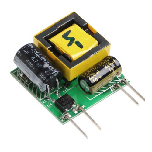
I found these modules, sold for a few buck only and rated for 5V 1W, that's 200mA.
![]()
It's probably going to need some conformal coating though but we're almost done.
However there must be a "fast reset" of the circuit : if the power is absent for more than 1/5s, the whole sequencer must be reset.
Power supply power-on sequencer
This device reduces the amplitude of current peaks when you power many power supplies at the same time