Johnny
-
AC Circuit Tested
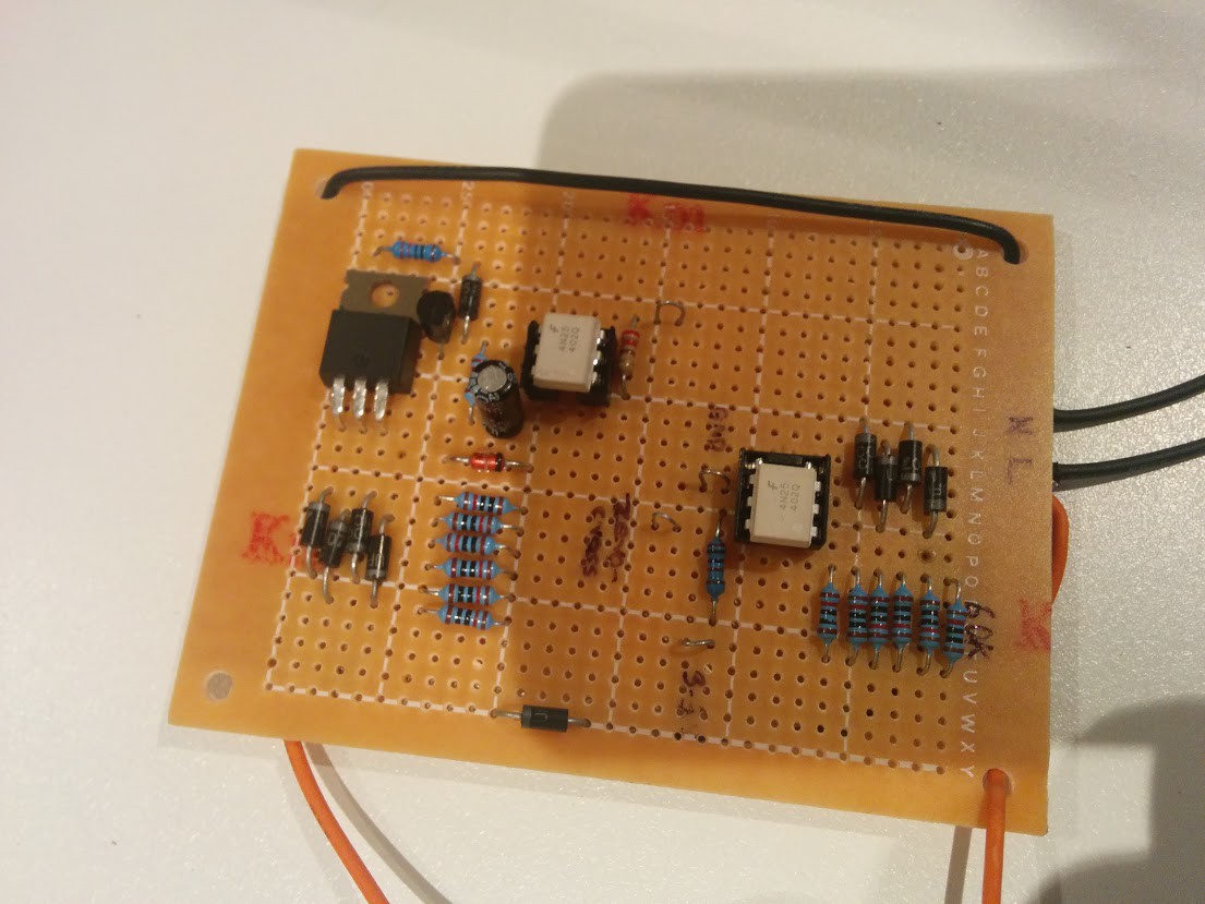
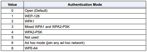
03/15/2015 at 14:38 • 0 commentsThe zero-crossing and AC switching circuit is tested and working. Next test is PWM. Those 6x10K resistors are supposed to be 2x33K. Didn't have any 33K half watt resistors. Therefore circuit will be smaller.
Please don't build and test a circuit like this unless you know how to do so safely. This circuit contains no transformer and is therefore un-isolated and should be treated, when powered, as all parts of the circuit are at mains voltage. I shouldn't have to say that 240V AC is HIGHLY DANGEROUS. If you attempt to measure this circuit with un-isolated lab equipment, you could potentially destroy your equipment and or yourself.
![]()
-
A Quick Simulation
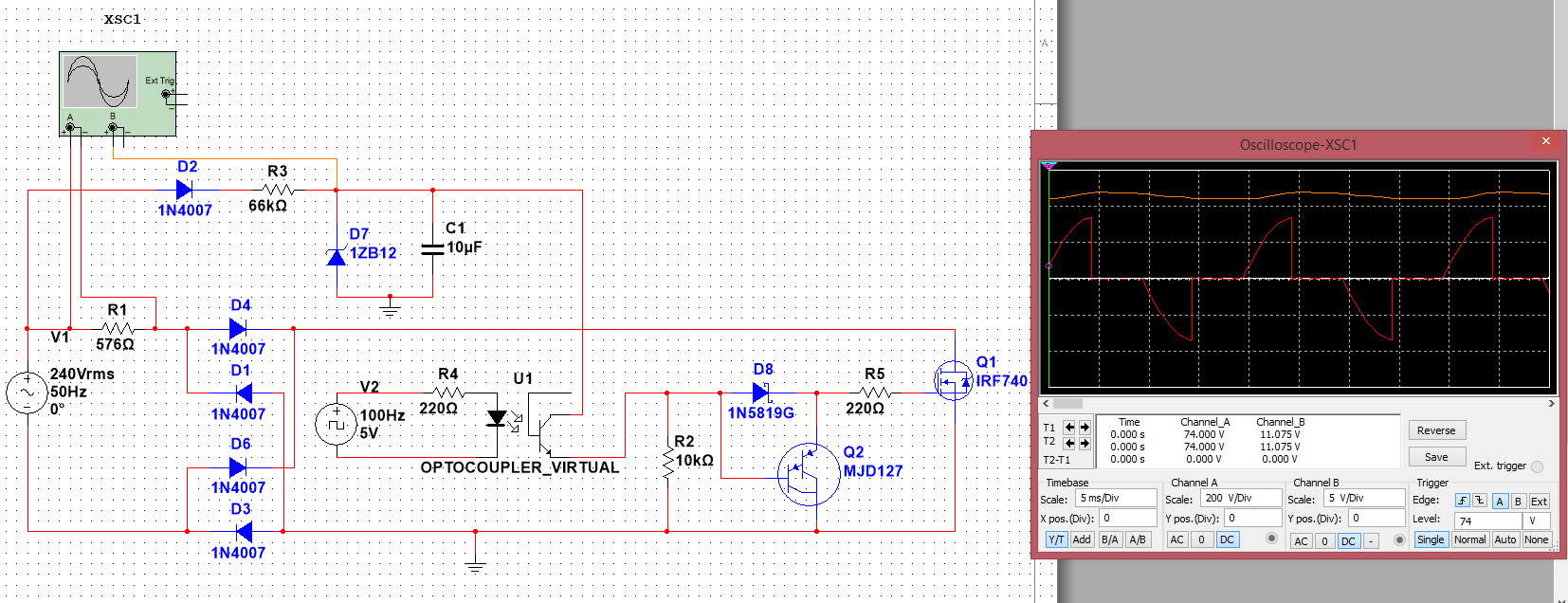
03/11/2015 at 12:57 • 0 commentsmade a quick design of the AC switching circuit in multisim, the concept seems to work well. Ignore the components used here, the parts I plan to use weren't all in the multisim library. And also you'll notice there is no zero-cross detection in the simulation, don't worry I haven't forgotten it.
![]()
-
I'm Back!
03/07/2015 at 06:35 • 0 commentsFinished Uni. Now back into the swing of things. Decided to take a new direction with the project thanks to RISC's suggestion. I'm now waiting for the MGC3130 Hillstar development kit to arrive so I can start playing with this chip. In the mean time I've started working on the AC switching circuit, followup posts coming soon.
-
Too Busy
08/18/2014 at 11:32 • 0 commentsUnfortunately uni workload is large at the moment. I'll have to get back to this at a later date. S
-
Sensing Hand Location/CTMU Overview (Old but useful)
07/17/2014 at 06:31 • 0 comments![]()
To electronics, a person's body looks a lot like a capacitor. The iron in our blood act as little capacitors in parallel. All the small capacitances add up to a capacitance that can be sensed by electronic circuits. By knowing what capacitance should be seen by a particular circuit when no hand is present and measuring the change in capacitance when a person's hand moves closer, the 'Proximity' of the hand can be sensed.
Charge Time Measurement Unit
To sense the presence of a user's hand, a change in capacitance needs to be measured. I will be using a PIC microcontroller's CTMU peripheral to do this, as the microcontroller will have all that is required to measure this change in capacitance (no need for external resistors like other methods).
![]()
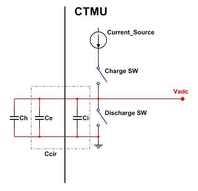
The CTMU contrains a precision current source and MOS transistors (Charge SW & Discharge SW) to charge and discharge the capacitance
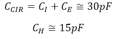
Ccir, where Ccir is the total circuit capacitance (without hand capacitance Ch). Cir = internal capacitance Ci (ADC & switches, etc) + external capacitance Ce (antenna). Which equals roughly 30pF, but Ce will depend on your capacitive antenna design. Ch equals the hands's capacitance, which when touching is anywhere from 7pF - 20pF.
![]()
Before taking a reading, we first discharge the capacitance by setting the IDISSEN bit (Discharge SW) in the CTMUCONH register. Next we set a timer to overflow and interrupt at a particular period of time to allow the capactiance to discharge. After such a time, we reset the IDISSEN bit and start the current source. This is done by the setting the EDG1STAT bit (Charge SW) in the CTMUCONL register. This current is trimable by adjusting the ITRIM bits in the CTMUICON register. The timer is again set and we wait for the capacitance to charge for that same time period as before. Then we turn off the current source (EDG1STAT = 0), take an ADC reading, and the cycle begins again.
If we know the current and the time that we are charging the capacitance for, we can determine the capacitance at the input by recording the voltage seen by the ADC and using the Current-Voltage relationship formula seen below.
![]()
Because I is constant and we are only interested in charging from 0V ( V(to) ), the equation simplifies to:
![]()
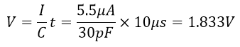
If the current source is 5.5uA and we are charging for 10uS, when no finger is touching the ADC would measure:
![]()
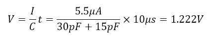
And when you finger is touching;
![]()
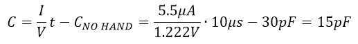
Because we know the voltage/capacitance when no hand is near, we can also measure the capacitance added by a hand getting near.
![]()
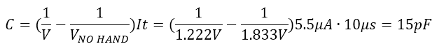
or
![]()
Hand Location
If four capacitive antennas are placed in a rectangle arrangement, one can determine the approximate location of the hand by comparing the sensed capacitance/voltage of each antenna.
![]()
-
Configuring a WiFly Module (Old, check out ESP8266)
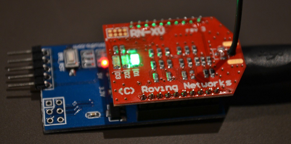
07/06/2014 at 17:18 • 0 comments![]()
In this project log, I'm going to explain how to setup a WiFly module using an XBee explorer, so you can start using it with a microcontroller on your home network.
Required Parts:
- WiFly RN-XV - https://www.sparkfun.com/products/10822
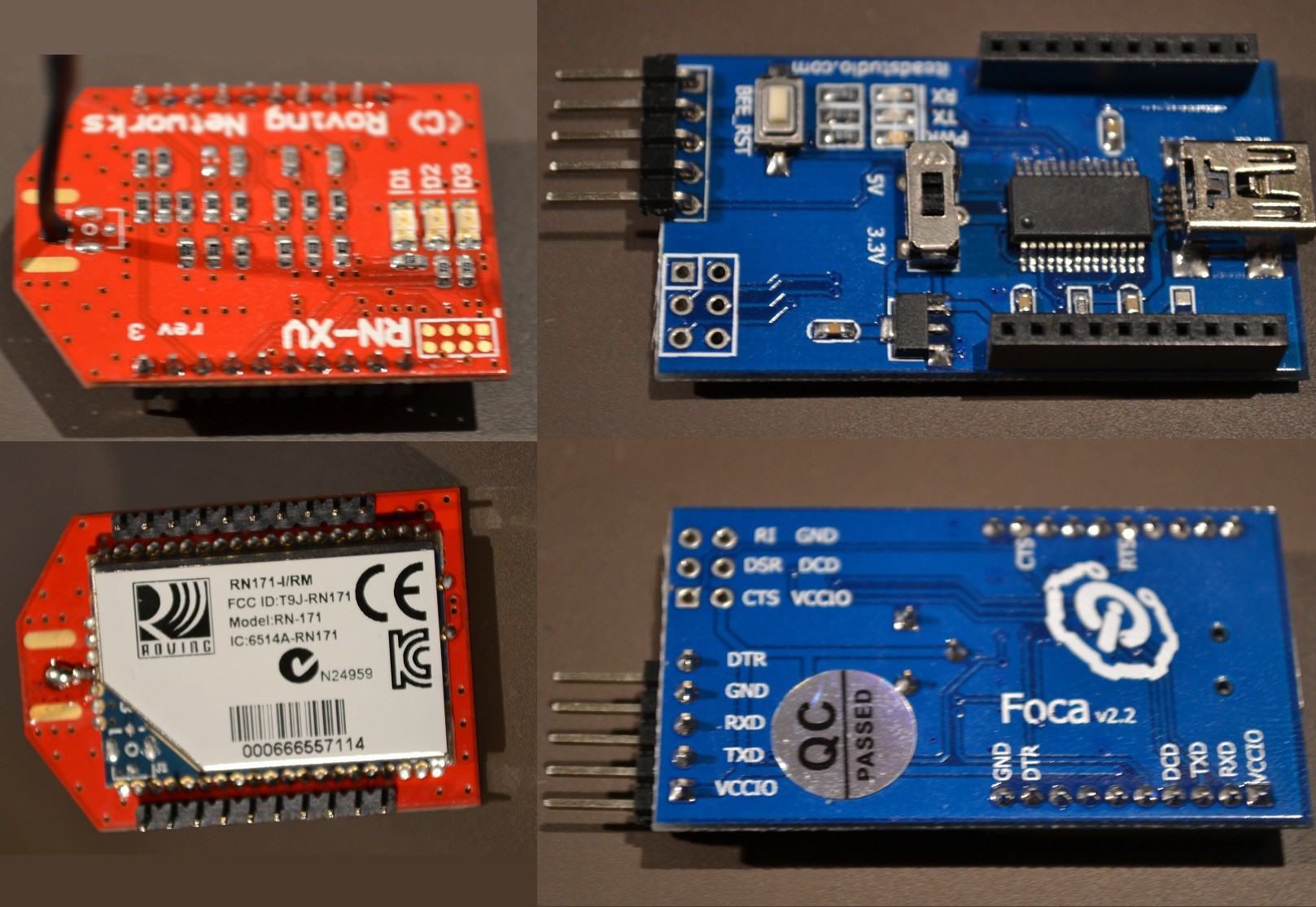
- Xbee Explorer (I use the FOCA v2.2 by Itead Studio) - http://imall.iteadstudio.com/im120525005.html
- USB cable
![]()
Required Software:
- PuTTY or Tera Term - http://www.chiark.greenend.org.uk/~sgtatham/putty/download.html
- WiFly User Guide - http://ww1.microchip.com/downloads/en/DeviceDoc/50002230A.pdf
![]()
*NOTE* - Make sure you use the switch on explorer to supply 3.3V! Don't worry about the UART RX pin though, it's 5V tolerant.
Getting Started:
- Step One - Plug the WiFly module into the XBee explorer, and plug the USB cable into the computer. Depending on the explorer you use, you may need to download the drivers. Mine requires a driver for the FT232RL chip. Found here: http://www.ftdichip.com/Drivers/VCP.htm
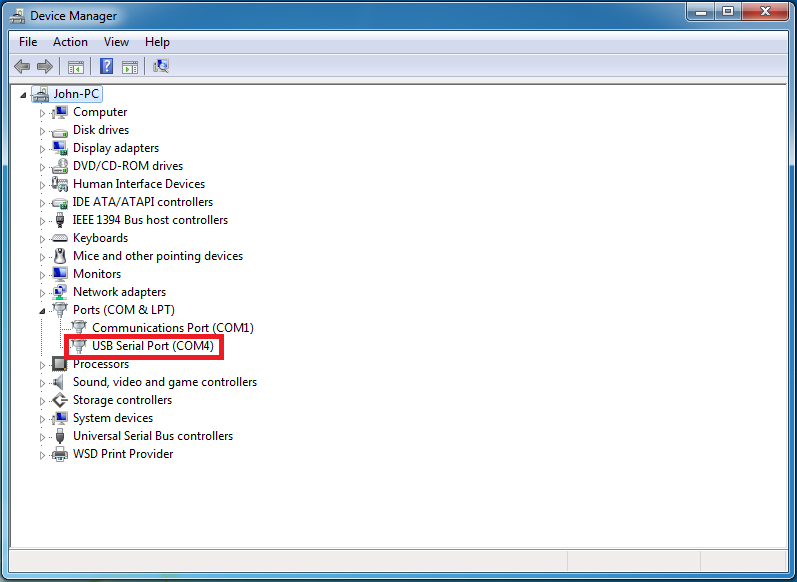
- Step Two - After your drivers are installed, Open "Device Manager" and under "Ports (COM & LPT)" you should see your device and port number. Jot that down.
![]()
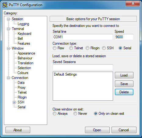
- Step Three - Open "PuTTY". Under "Connection type:" select serial. Under "Serial line", type the COM port for your explorer. e.g. "COM1". Under "Speed", you can leave "9600". This is the correct baud rate for the WiFly from factory.
![]()
Step Four
- Now just click "Open".
Command Mode
Command mode is the mode in which your WiFly module will accept commands via UART to change settings and perform actions. When powered up, by default the module is not in command mode. We need to enter command mode so we can start configuring the device. To enter command mode, make sure nothing is transmitted to the module for 250ms or more, then you must send "$$" and wait another 250ms or more afterwards.
What You Type:
$$
Response:
CMD
The "CMD" response from the module let's you know you're now in command mode.
Connecting to Your Network
Now that you are in command mode, lets tell the WyFly module what type of security our WiFi network has. I have WPA2-PSK. Yours may be different. Check your router settings.
![]()
Based on the table above, I enter the following command and press enter:
set wlan auth 4
because the module will echo back to you in command mode, you will see:
set wlan auth 4
AOK
<4.00>
The "AOK" is a response from the module verifying that the module understands and has performed the command successfully. The "<4.00>" response is the firmware version of the module. From now on I'll just show the responses.
Next I want to set my WiFi's SSID. My command is:
set wlan ssid TP_LINK_B3DFFE
AOK
<4.00>
Next give it your password:
set wlan phrase password
AOK
<4.00>
I want my module to auto-connect to the network when it is powered on, so:
set wlan join 1
AOK
<4.00>
When the module is working as a HTTP server, I don't want certain command responses to get through to the client. So I turn them off.
set comm remote 0
AOK
<4.00>
set comm open 0
AOK
<4.00>
set comm close 0
AOK
<4.00>
Next I set the port I wish to work on. Because I want to use this as a HTTP server, I set my port to 80:
set ip localport 80
AOK
<4.00>
And finally I need to save my settings and reboot so they take effect:
save
Storing in config
<4.00> reboot
*Reboot*
Now my WyFly module is ready to use! I recommend setting your baud rate higher then 9600, I use 38400 makes pages load faster.
For more information and commands, go to: http://ww1.microchip.com/downloads/en/DeviceDoc/50002230A.pdf
All the best.
-
Embedded Server Basics (Old but useful)
07/06/2014 at 12:33 • 0 comments![]()
![]()
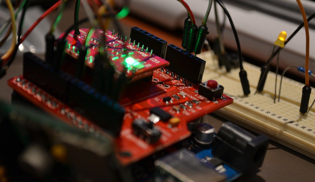
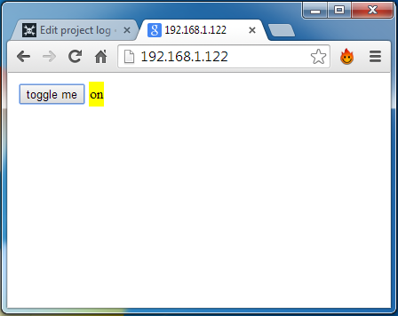
A lot of embedded/home-automation server demos and tutorials with WiFly and arduino use html forms with submit buttons on their websites to send HTTP 'GET' or 'POST' requests to change an output on the arduino, and in turn reload the entire page with updated statuses (inputs and outputs). This is OK, it's simple, but how will you know when an output changes external to the website?, e.g. a button on the arduino turns on an LED. Also each time you push a website button, you need to reload the entire page! This is a huge waste of processing time and more importantly, your time!. This "form submit" method is primitive..
The ideal embedded/home-automation web server's page has buttons that immediately effect the outputs in the real world. Also the outputs and inputs are known and are being displayed in real-time, all the time.. Read on to know how this can be done...
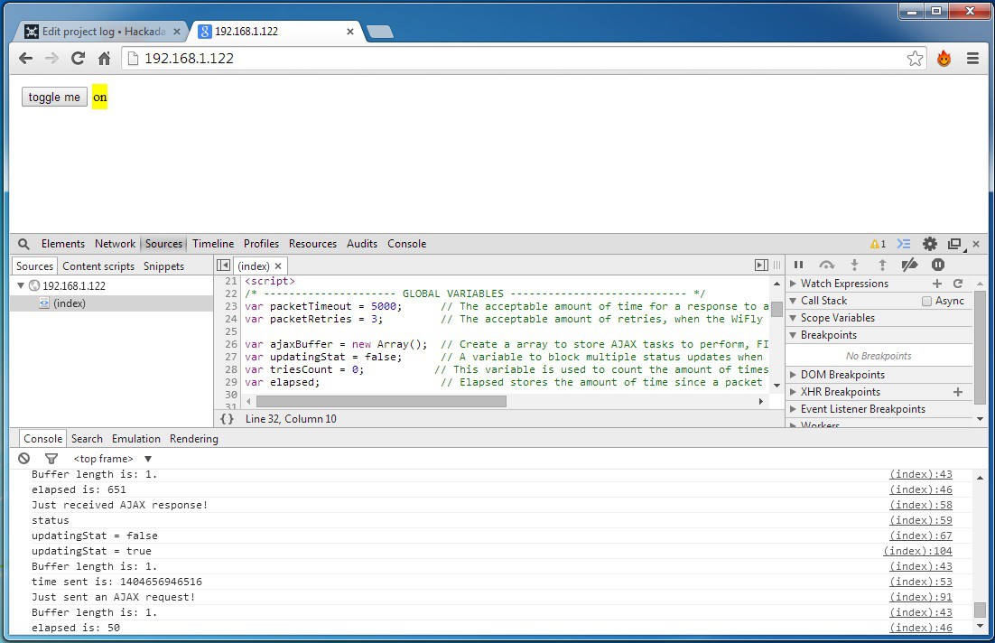
So I've been developing using the Asynchronous JavaScript and XML method, "AJAX!", to do these tasks. This means NO RELOADING. I can effect the arduino's outputs, and get regular updates automatically of the current states of the inputs and outputs and display them almost immediately, and no reloading :).
To do this a clients browser needs to create an XMLHttpRequest() object in javascript. This is used to send and receive data from a server, no reload (sorry for repeating myself).
Here's some example code:
An AJAX "GET" request in your javascript code will look something like this:
var xmlhttp = new XMLHttpRequest();     // Creates a new XMLHttpRequest object
xmlhttp.open("GET","wepage.htm",true);  // Use open, with the method "GET" or "POST",
xmlhttp.send();                         // the page you're requesting, and asynchronous or
                                        // synchronous. Finally, send it.
Upon the WiFly module receiving the request, the module will send something like this over serial to the arduino:
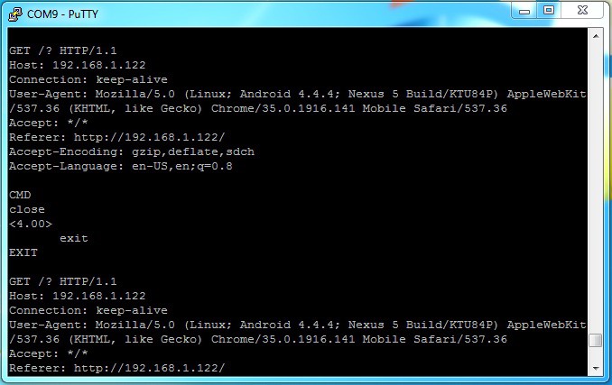
GET /wepage.htm HTTP/1.1 Host: 192.168.1.122 Connection: keep-alive User-Agent: Mozilla/5.0 (Linux; Android 4.4.4; Nexus 5 Build/KTU84P) AppleWebKit/537.36 (KHTML, like Gecko) Chrome/35.0.1916.141 Mobile Safari/537.36 Accept: */* Referer: <a href="http://192.168.1.122/">http://192.168.1.122/</a> Accept-Encoding: gzip,deflate,sdch Accept-Language: en-US,en;q=0.8<br>
Now the arduino is sitting there waiting for a particular sequence of characters, maybe "$1":
GET /$1
and this could mean to the arduino, "turn on LED1".
Likewise, if the arduino see's the following, it could mean, "I want to know the status of everything":
GET /?
If the website needs text in its response from the WiFly, like the example above, after the arduino has detected "GET /?", the arduino would respond with something like:
arduino code:
if(digitalRead(8)==0){
    Serial.print("off");
}
else{
    Serial.print("on");
}
delay(300);
Serial.print("$$");
delay(300);
Serial.print("close\r\n");
Serial.print("exit\r\n");


result:
on$$close
exit
Where "on" is the text sent back to the website. After that, there is a pause of 300ms, then the arduino sends "$$" followed by another 300ms delay. This puts the WiFly into command mode (the stuff just sent won't go through, don't worry) where the TCP connection can be closed ("close") and then command mode exited again ("exit") ready for more requests.
Meanwhile the clients web browser is there waiting for the response, in some sort of javascript loop:
if(xmlhttp.readyState == 4 && xmlhttp.status == 200){          // If the response is ready
    document.getElementById("status").innerHTML = xmlhttp.responseText;
    xmlhttp.abort();                          // Put the captured text inside the html
    xmlhttp = null;                           // element with the id "status" and
}                                                 // end the session.
When the browser receives the response successfully, the property "readyState" will equal 4 and "status" 200. Then you can grab the response text, place it inside an HTML element, and end the session.
This is the basics of AJAX and basis of achieving a pretty good embedded/home-automation web server. With the main goal of no refreshes.
Working Webpage and Arduino CODE:
If you want to check out my code for a simple embedded server that turns an LED on and off using AJAX and has some pretty cool features, such as a looping FIFO buffer for tasks, packet timeouts, and connection loss notification please visit:
https://github.com/johnnydrazzi/simple-WiFly-server
What you will need:
- WiFly Module
- XBee explorer (I use the FOCA v2.2 by Itead Studio)
- XBee shield
- an Arduino of your choice
- SD card & SD Shield (I used one by Mikroelektronika)
- USB to Serial (FT232RL or the like) (optional)
- Jumper wire, breadboard, LED and 330R resistor.
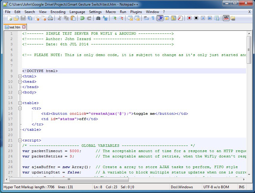
Recommendations:
I recommend, if you plan on building your own website, download Notepad++. It's free, easy to use and it will color code your code and help find your syntax errors.
![]()
Secondly, download PuTTY http://the.earth.li/~sgtatham/putty/latest/x86/putty.exe. This program is awesome for setting up the WiFly module and sniffing that uart chatter.
![]()
Lastly, I use console logs a lot in the javascript code for debugging. Pressing F12 on most browsers will bring up the console.
![]()
-
Back to Web Development
06/27/2014 at 07:11 • 2 commentsThe majority of this project is software based. I'm currently spending time on designing a website for the home automation server (Hub). Spending the a lot of my time on w3schools.com refreshing my javascript and AJAX knowledge.
I want buttons and text input etc to have immediate effect on the nodes without refreshing the website. This is important as reloading an entire website is annoying and with an 8-bit micro using uart, can be time consuming. The reason for using an 8-bit micro such as Arduino to serve the website is, for one, most people start out using simple microcontrollers and I want people of all skill levels to be able to have a go. The other reason is, I believe a device like a raspberry pi is overkill for such a task and a pain to setup and wait for it too boot up.. I'd like to keep costs down too..
I will upload the code for a basic website with asynchronous controls and visual feedback of the "real-time" outputs state and Arduino code for people to play along with soon...