-
1Step 1
Project's background.
The project must be:
- Modular
-Pieces Not metallic : printables
- Pieces metallic: cheap and easy to find
- Open Hardware ( mechanical parts and electronics parts).
- Open Software.
When We say MODULAR, We say that the construction of the mechanical part must be solved with a module or with a limited number of modules those who will be assembled as we needed. These modules must follow too the background of the project and must be resized easily without changing his characteristics. As we advance in the development of the project we will explain about this concepts.
-
2Step 2
![]()
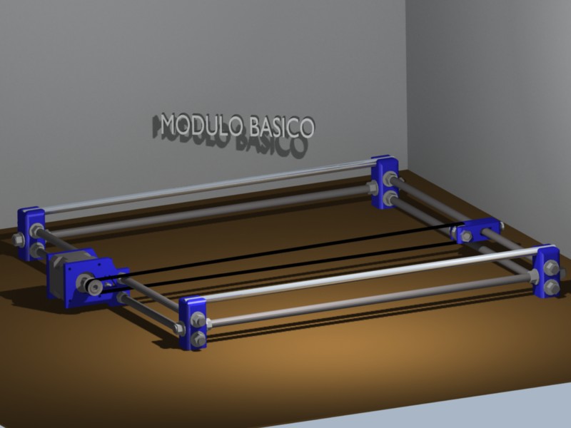
This one is the basic module that I use for the construction of the plotter XY and that I will use also for the next projects. You can see that it's the same structure of the axis Y of the 3D printer Prusa I3. Also it is possible to observe that to change the width or the length of the structure we only need to change the bar's size and the belt's size.
-
3Step 3
![]()
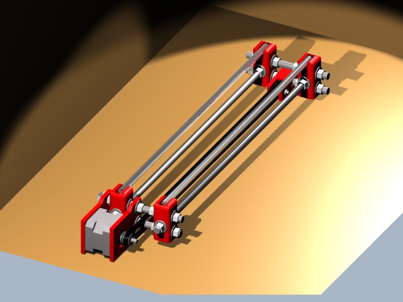
Here, the basic module modified to be used as axis X of the plotter. It is exactly the same structure only the size of the rods has been modified and we have exactly those that we needed and keeping strictly background's rules.
-
4Step 4
![]()
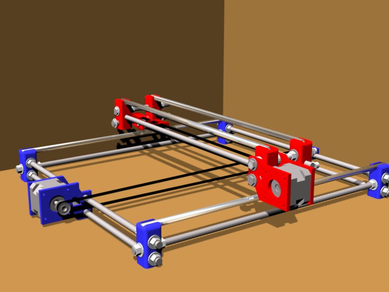
We have two modules suitably resized to be used as axi X (red) and axis Y (blue). We needed this two similar structures, and placed it in orthogonal form, that is, his axes displaced 90 degrees one respect the other. In this image we see how we must place them. It is possible to estimate that at the moment, the axis X it's "floating" on the axis Y. We have to find a way of joining the axis X with the axis Y. But it shouldn't will be a fixed union, since we must not forget that the whole structure of the X axis must move along the Y axis. We will see it in the next step.
-
5Step 5
![toma_union]()
This green piece join the two structures. With the hole for the linear bearing in the bottom part and the space for the corner pieces in the upper part. With four of this green pieces and four linear bearing we can join the two structures and can move the entire X axis along the Y axis.
-
6Step 6
![toma_todo]()
The complete mechanism. The light blue pieces,the rod,and the magenta pieces, connect de X axis to the belt moved by the motor in the Y axis.
In the X axis, the four green pieces form a platform where we will fix the pen holder. The yellow piece joined to this platform and joined too with the magenta pieces it's connected by the belt to the X axis's motor.
-
7Step 7
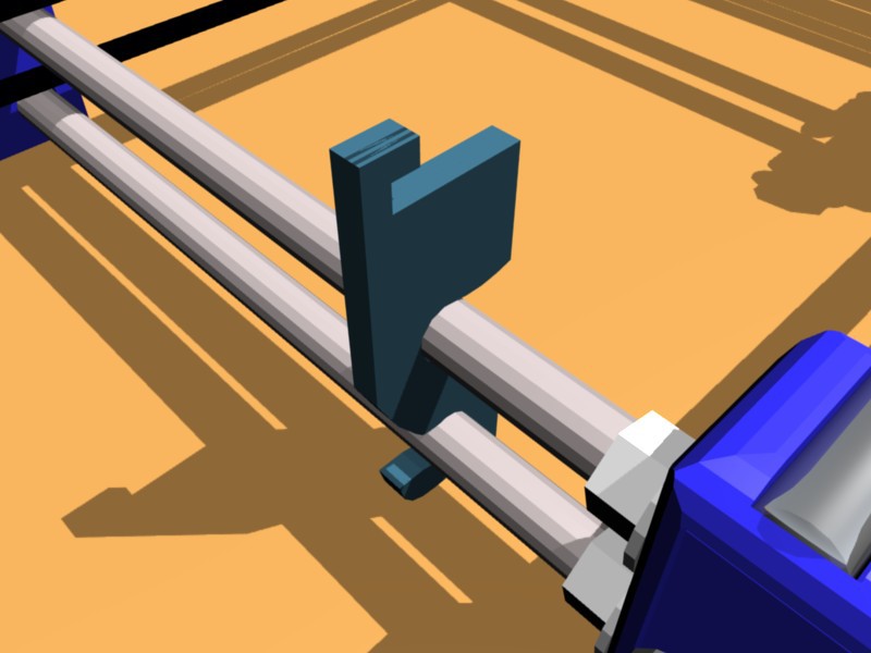
![]() Four of this pieces are the most simple methode I find for support the drawing surface.
Four of this pieces are the most simple methode I find for support the drawing surface. -
8Step 8
![]() Here can see how ensamble it. And how to keep the paper in place with some binder clips.
Here can see how ensamble it. And how to keep the paper in place with some binder clips. -
9Step 9
![]() A general view including the penholder
A general view including the penholder -
10Step 10
![]() Another point of view. Can see the cables chains
Another point of view. Can see the cables chains
Modular cartesian machines
A serie of 3 cartesian machine: plotter XY, cnc mill and a 3d printer, with a DIY, modular, all printable and cheap system
 jvsalatino


 Four of this pieces are the most simple methode I find for support the drawing surface.
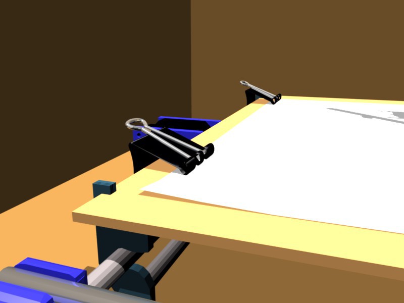 Here can see how ensamble it. And how to keep the paper in place with some binder clips.
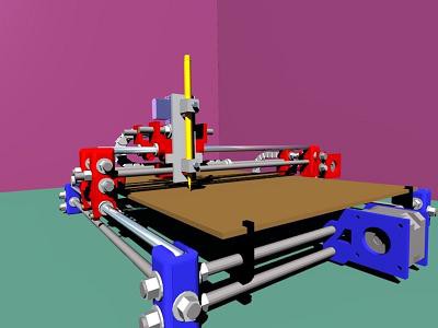 A general view including the penholder
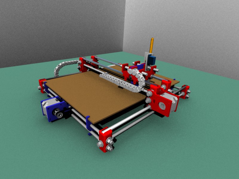 Another point of view. Can see the cables chains
Discussions
Become a Hackaday.io Member
Create an account to leave a comment. Already have an account? Log In.