Josh
Josh-
Know G-code, Fix Cam Package Errors
06/09/2016 at 17:55 • 0 commentsNew files for SideA-1.ngc and SideA-2.ngc are posted in conjunction with the following.
So it has taken me a few weeks to get some time to look into the issue with the rockers and cutter compensation. I assumed that it was an issue with how Mach 3 interpolates between changes in cutter compensation, but it may be simpler than that.
Dxf2gcode is the software that I used to create the gcode. When the problem occured, I looked at the code and saw that it was applying what appeared to be the proper compensation in the code and Mach 3 printed what appeared to be the correct cutter compensation path. What I didn't do was take 30 seconds an confirm the actual Gcode command issued.
Assuming I needed new lead-ins each time I changed direction, I began to manually add a small offset cut at the end of each path prior to the direction change to provide a new lead in. That's when I noticed that the code was calling G40 at each direction change rather than the required G41 (LH) or G42 (RH). G40 SHUTS COMPENSATION OFF. It wasn't apparent on the Mach3 sim because the first cut produced the proper compensated path, so without rotating the view, each subsequent pass appeared to follow the last.
So only the first cut was applying compensation. Each cut depth after was just cutting on the uncompensated line.
I have replaced the G40 commands with the correct G41 and G42 commands, and I'll be giving it a shot again as soon as I can!
I'll submit a bug report to the Dxf2gcode project.
(edit: after exploring some settings)
It appears that there is an option to turn off compensation between cuts. When this option is enabled, it successfully applies the correct compensation on the next pass. So I will now utilize this option, even though I think it is still erroneous without that option.
-
Phase 2 + 1 Files Uploaded!
05/30/2016 at 21:15 • 0 commentsAll of the files for Phase 2 are now available, including the SVG, DXF, and G-code. All files CC BY-SA 4.0. These files are untested at the moment, and the toolpath problem on the rockers still has not been corrected, although I believe it is a Mach3 issue. I will update these when I get a chance.
All drawings needed for Phase 1 are now uploaded (these are the same as you would find in ONSHAPE, so now you don't need an ONSHAPE account to get the drawings.)
I will do a write up later for the Phase 1 instructions, but as of now, all files are available for those who wish to use them, and for inclusion in the Hackaday Anything Goes competition.
Feel free to ask any questions! The point of this project is to help those in need of some starter CNC info!
-
Files for Phase 2
05/27/2016 at 18:55 • 0 commentsI am working on uploading files for Phase 2. Please check the files section for updates. I will follow up later with files for Phase 1. As I will be out of town for the weekend, I'm not sure if I will get all files posted prior to the deadline, but we shall see.
-
Phase 2: Failure on Multiple Levels
05/25/2016 at 13:56 • 0 commentsThere were 3 main failures that occurred last night when trying to run the procedure.
- Cutter compensation did not function properly
- Manually jogged into a hard stop
- Wood size was different than I thought
This video shows a time lapse of the first try of producing the rocking horse cutouts:1. Cutter Compensation Failure
This is the most baffling of the 3 issues and the only one that does not appear to be a human error at first glance. When cutting the rockers, the tool must reverse course. When cutting in a clockwise direction around the perimeter of an object, the compensation is set left, so that it cuts to the left side of the line by the tool's radius. When cutting CCW, then it should compensate right. The gcode for the rockers does not cut out a full closed loop, because the rockers are larger than the Mill's working area; only half of a rocker gets cut out. Because I had a recent issue with cutter compensation in Mach 3 that caused the tool to take a few small "bites" out of my work piece, I fully inspected Mach 3's tool path prior to starting to ensure there was no obvious violation of the tool path.
What happened during the milling operation appeared that the cutter compensation was not switched when the tool reversed, causing the machine to cut on the wrong side of the perimeter of the rocker shape. After inspecting the code, it is obvious that the cutter compensation is coded correctly but Mach3 is not interpreting that code correctly. It's pretty hard to see in the following video, but when the cutter reverses direction on the rocker, it strays to the wrong side of the tool path, taking a large swath off of the part. Luckily my spindle and tool are large enough to handle it, but if this had happened with a smaller tool or harder material, this would have been a catastrophic event and caused something to break.
The tool reverses right after the "oops" caption when I took off a corner of my work hold-down. That happened because of failure number 3 below. Turn your volume down, the music I added is just as annoying as the router sound that was removed...
So my resolution is yet-unknown, but I suspect its the way that Mach3 interpolates a change in cutter compensation between points, and it may be that it thinks its on the wrong side even when its on the correct side, and does some interpolation that causes the cutter to wander off the desired path. A little reading suggests that cutter compensation doesn't like a change in direction greater than 45 degrees, and since I'm changing direction completely, this may be the issue. Another issue may be that I'm essentially starting and stopping without a lead-in on each plunge because I'm swapping the cutter compensation to the opposing side.
When I manually wrote the code originally, I never reversed direction, instead I called the same profile multiple times and fully retracted and moved to the start of the profile then replunged. So I have two options that I see available - 1) add code to lead-out then plunge and lead-in on each reversal of direction, or 2) simplify the code by taking the first profile that dxf2gcode produces and make it a subroutine and add a retract and repeat the lead-in code on every plunge. Option 1 is less work, but option 2 is sure to work. HMMM decisions decisions. I guess option 1 would forge new territory and confirm if it is a problem with interpolation after a change in direction... I'll go with that.
2. Manually Jog into a Hard Stop
My mill does not have limit switches at this time, so when I started, I knew that I couldn't shut the machine off or risk loosing the position. Then after the first pass cut was complete I accidentally jogged it right into a hard stop. This threw off the actual x position quite a bit. I know that Mach3 allows resetting the position by touching off of surfaces, but I didn't know how to do that. So I told the machine to move to a known drilled hole, at which point the drill was NOT over the hole. I then shut off power to the stepper drivers, and manually move the x axis until the drill was aligned with the hole visually. When I restored power to the steppers and ran the drill code, amazingly it was lined back up! (at least close enough that I couldn't see any issues with the location of the follow-on holes. So that's how I fixed my screw up there...
3. Wood Size Different Than I thought
This is a common lesson in "measure twice, cut once." I made an assumption that my "1 foot" board was .25" smaller at 11.75" but it turned out to be 11.25". This missing .5 inches was enough to cause my tool to cut through the edge of the wood, and because my work clamps were not located on both sides of this cut through, a large portion of the board became unsupported on one side. The opposite side did not have enough clamping force to hold it, and the tangential cutter force moved the board on the table. This is another point where I was lucky that I was cutting wood, because the movement of the workpiece did not cause any damage to the tool or spindle. If this was a metal part, lots of bad would have happened.
Other thoughts on fixturing
Pin fixture
My theory so far has been to drill and use alignment pins to keep the boards in place and allow accurate indexing when moving the board on the table. One issue with this is that when I drilled the alignment holes, I used a standard 1/8" drill, and it wandered significantly through the workpiece in at least one case. In the future I will use a 1/8" bottom end mill and go as deep as it will go, following with the drill only if necessary.
Another obvious issue is that I'm violating a basic rule of datum creation: you can only have one fixture for each degree of freedom. This means that a single pin fixes x and y directions, and rotation about that pin is the only remaining degree of freedom. Using a second pin tries to fix rotation but also double dips on one of the previous datums. This works for me only because the drilled holes are larger than the pins I'm using by more than the positional tolerance. I really need to pin only one place, then put a pin against the outside edge of the board for the rotation alignment. The fixture is currently set up for this, so it would be easy to try.
Here's a video showing some of the fixture pin drilling.
Fence
The pins are also very time consuming. Today I have been contemplating ditching the pins and machining a fence on one side of the scarfboard by screwing down a strip of wood and taking a cut along it to square it to the y axis. This would allow me to place a board against it, fixing the board in the x and rotation degrees of freedom, and then I would only need a reference for where to place the board to fix the y dof. Since there is only one part that is critical to align between setups, and all other parts are cut fully in their own setup, I could explore the possibility of simply using scribe marks to align the pieces. This would allow me to eliminate a whopping 5 setups that are used to drill the alignment holes for the pins.
I'll be trying the fence next time.
-
Phase 1 Recap: Design Iteration
05/19/2016 at 17:09 • 0 commentsAfter building the horse from all of the parts, I ran into the following issues, and determined fixes for the next time:
- Rockers are too short! My daughter promptly flipped off the back on her first ride, and has subsequently gone over the front a few times as well. Easy fix: longer rockers! Keep the Rider's CG inside the "pie" shaped by the rocker radius and length.
- Mane. The mane was not thought out ahead of time, and I had to dremmel a slot in the back of the neck to glue in a bunch of yarn. The next horse will just have a wavy back that can be painted.
- Mouth Features. The mouth didn't really look like a mouth until we added felt features to accentuate the neck line. The neck and mouth should be redone to make it easier to envision, even before painting/felting.
- Streamlined Gcode. Now that I know how to write it, I can explore programs that will turn my drawings directly into gcode, and then modify the output directly if needed.
Next up: On to Phase 2!
-
Phase 1 Recap: Feeds and Speeds
05/19/2016 at 16:13 • 0 comments(edited to bring more accurate feed/speed guidance)
It seems that there are quite a few different ways to calculate feeds and speeds, but I'll give you my take.
Feeds - How fast you cut (how fast tool travels when cutting), in units/minute.
Speeds - Rate at which a rotating tool spins
Chip Load - the size of the "bite" that the tool takes on every cut.
I tried to do some research to find out some other people's ideal settings for cutting wood, but I never found any and I just decided to give it a go.
My Experience
My tool starting out is a 1/4" diameter, 2-flute straight cutter. This means it has 2 cutting surfaces and no spiral. I didn't choose it for any reason other than I had it in a box that I kept when I sold the lathe and it was still packed new in wax. I started out just setting my spindle to the max speed (25,000 rpm) and cutting slowly (20 in/min). This worked just fine, but I didn't get wood chips, I got wood dust. As I cut parts, I slowly increased the speed.
What I found was that somewhere around 70 in/min the dust started to transition into fine chips of wood. Chips would be an over statement, as they were more like delicate shavings. This makes sense, because the calculations really aren't that hard. Chip size = Feed/(speed*flutes). So my chip size is 70/(25,000*2) = 0.0014". This is about 1/3 the thickness of a sheet of printer paper.
I eventually pushed the machine up to 100 inch/min and it had no problems cutting through at a depth of 1/4". Redoing the chip calculation, I should be getting 100/(25,000*2) = 0.002" thick chips. These were nice chips that the vacuum easily removed and there was little dust formed in the process. I decided that I will target a 0.002" chip thickness for this tool moving forward.
Method to Figure out Feeds/Speeds
So to answer the great question: where do I set my feeds and speeds? High spindle speed and low feed rate sounds like a logical place to start, but DON'T DO IT! You'll set yourself up to burn up your tool and your work. The problem is that even though our tools appear to be "sharp" when you look at them under a microscope, the "sharp" edge has a radius. <This article> does a great job of explaining, but basically the radius of that edge seems to be on the order of .0001" and if your chip load gets close to this number, your cutter doesn't cut, it "pushes" or rubs the material. I'd suggest shooting for 10X this and aiming for a .001" chip load.
Here is a good method for wood:
- Calculate a starting feed rate such that you will have a chip load of about .001" The formula is Feed = chip load * RPM * #flutes.
- If your machine can't travel that fast, then calculate your spindle speed RPM based on your max feed rate: Speed = Feed/(chip load * #flutes).
- If your tool is excessively heating your work piece, burning or melting it, Either SPEED UP your FEED rate, or REDUCE your spindle RPM. Chips carry most of the heat away from the work, so speeding up the feed rate makes more chips to cool the tool, while reducing the RPM produces less friction and bigger chips at the same feed. This also means you probably aren't hitting the calculated values for either feed or speed for the target chip load.
- If you are getting rough edges, or can see a significant line between each cut layer, you are probably getting excessive tool deflection. Reduce depth of cut, take more passes to cut your part. You can also reduce your chip load, but this has a side effect of causing more heat. I found many people said not to set depth of cut deeper than the cutter's diameter.
- If you are getting corners that are not well-defined, you may have a backlash or acceleration issue. Reduce your velocity slope (acceleration) so that your spindle head will slow down for changes in direction. Be wary that lower accelerations may cause your machine to fail to reach the specified feed rate in some areas with lots of direction changes. This means you should reduce your spindle speed to try to keep the chip load higher.
- Listen to your machine. The sounds it makes will give you some indication of what it's doing. If the sound changes drastically, it may be a warning to stop before something breaks!
I hope my experience will help someone else trying to start off! Feel free to ask me questions - I'm likely to have screwed up the same thing!
-
Phase 1 Recap: Making a Part Larger Than Your Table
05/19/2016 at 13:28 • 0 commentsThis is a short log detailing my method to machine the rockers, which were much longer than the router table.
Continuity
The biggest issue I faced with my machine is no Homing. So when I wanted to make a part longer than my router table, I had to ensure that the machine maintained its coordinates and didn't reset the home position during the whole process.
Fixturing - Index Holes
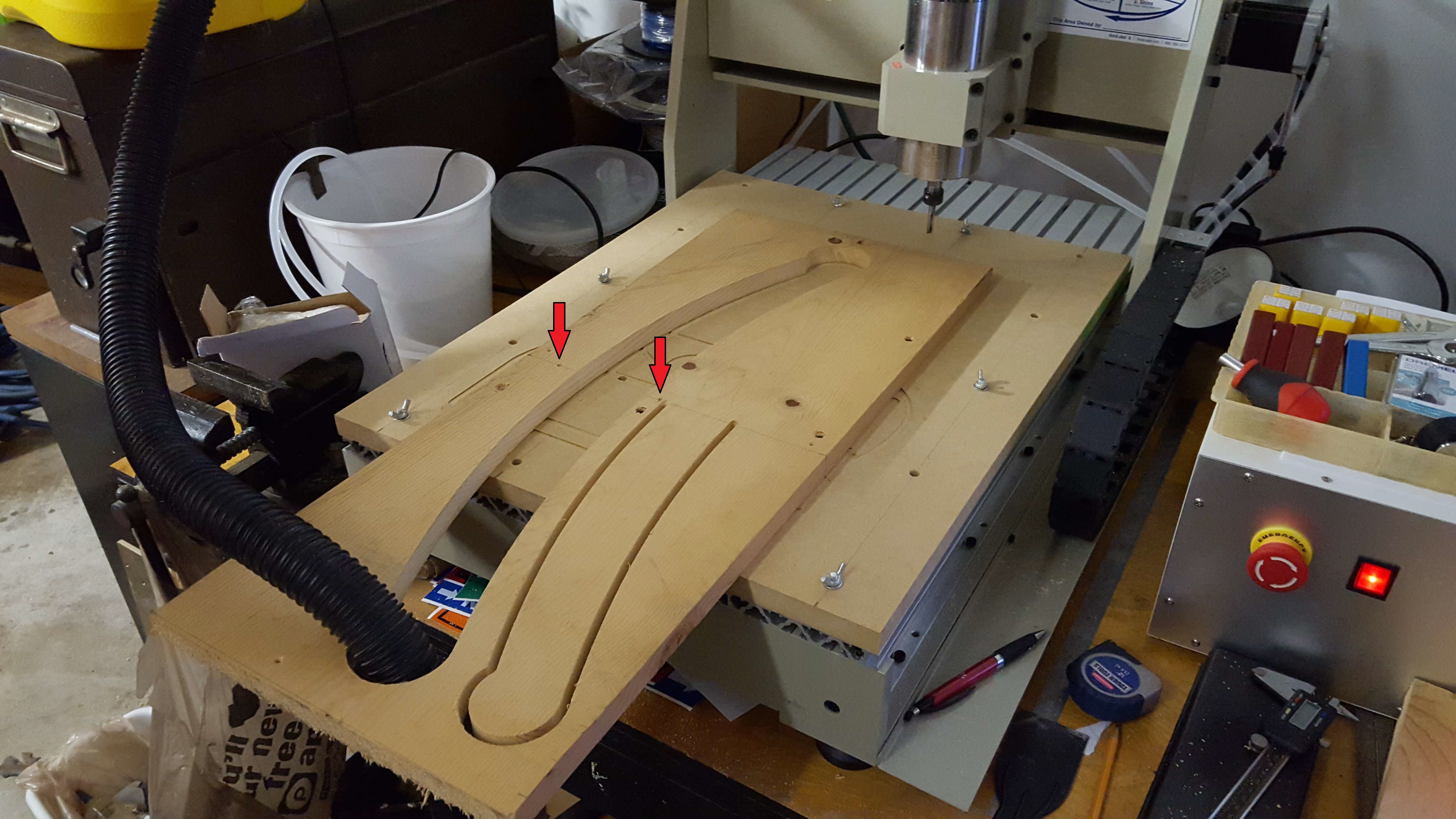
Although the full rocker wouldn't fit on the table, half the rocker easily did. I wrote my gcode file to cut half of the rocker at the centerline, so that I could flip the piece end-over-end and cut the other half of the rocker. The only thing I needed was an accurate way to flip it. I did this by writing a second gcode file that first drilled two holes, one on either side of the centerline of the rocker, that went all the way through the stock and into the scarfboard. I then used dowel pins in the holes to align the stock when I flipped it. Since I was cutting exactly half of a rocker, I could use the same gcode file for each side. In the image below its hard, but you can see the 1/8" drill holes (red arrows) used for indexing the board when I flipped it.
![]()
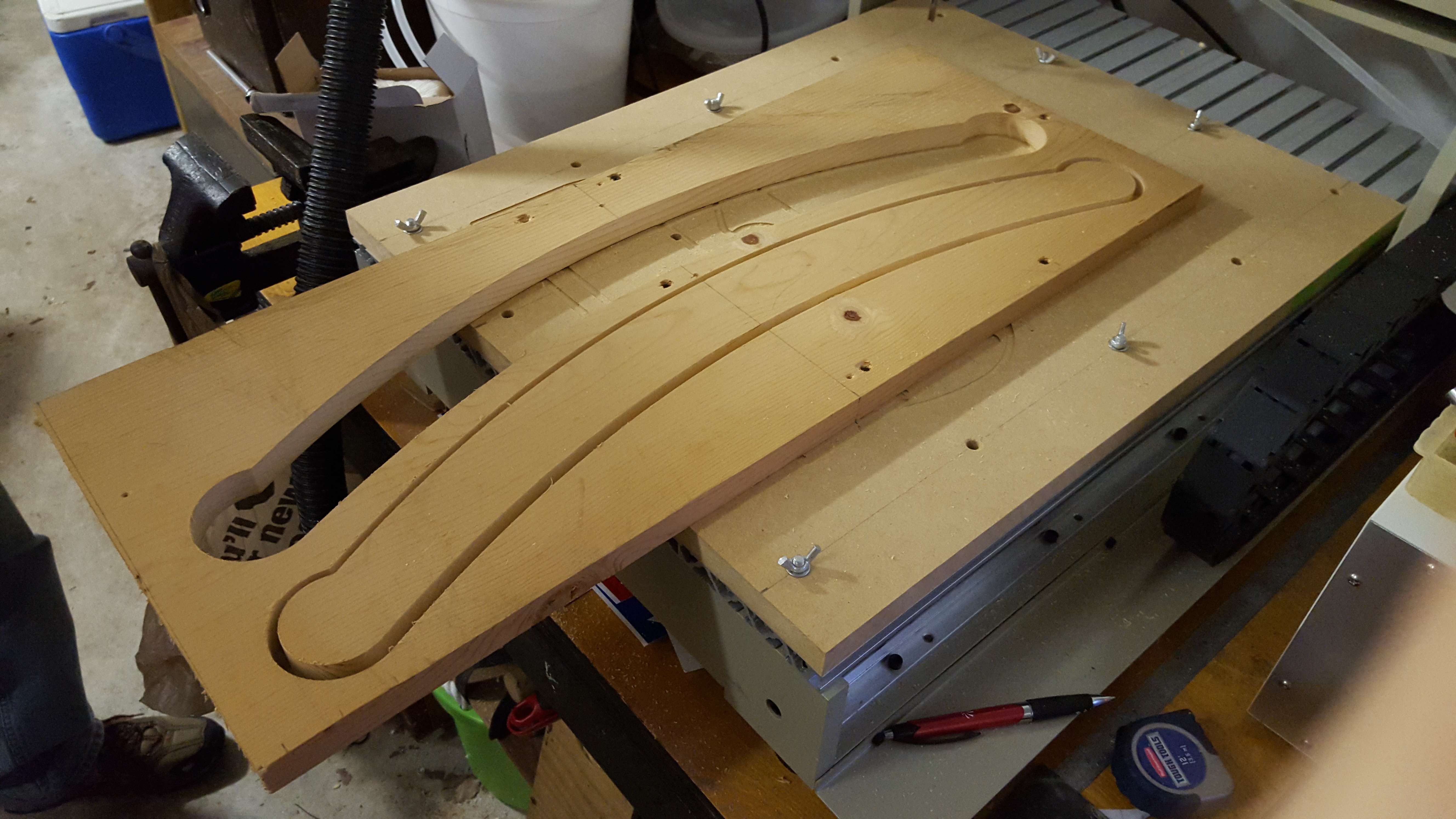
And here is the final cut:
![]()
Gcode Lessons
Since the rocker is shaped using only circles, cutting half of the rocker only required 4 lines of gcode for the tool path: one for the bottom surface, one for the fillet between the bottom and the end, one for the end, and one for the top. Adding gcode for the plunges and I was able to write the gcode for this part manually in a few minutes. I did have a major problem when I first wrote this code, however. I hand coded it then ran it using Camotics free simulation software. It looked great! Then when I loaded it in Mach3, the tool path visualization was completely wrong. It took me some research to find that gcode specifies relative arc center points by default, separate from the absolute (G90)/relative(G91) coordinate move setting. I was using absolute coordinate moves (G90) but Mach3 thought I wanted relative arc centers, so it was putting the arc centers in the wrong location.
I changed the gcode by putting in the relative center locations and everything worked great, then I discovered that I could have used G90.1 to switch to absolute IJK mode and not changed the gcode.
-
Phase 1 Recap: Learning CNC the Hard Way
05/18/2016 at 22:04 • 0 commentsExciting Beginings
Last year I decided to sell my metal lathe, a 40" gap-bed behemoth, and use the money to buy a Chinese CNC6040 router. I had the lathe for a long time and rarely used it, so the swap made sense to me.
Before I got my Chinese CNC6040 I had already made an attempt to build a 3d printer based on the SeeMeCNC H1. That printer sucked. I got it to print once, and it wasn't a very good print. I then spent about 4 years trying to tweak the printer to get it to print better before it started to fail all over the place. So when the CNC came in the door, the H1 got wholesale dumpped in a box on a shelf so that I could use the computer for the CNC.
Prior to getting the CNC, I already had some experience with Mach3 and setting up the hardware, but to be honest, gcode was still almost black magic to me. I just knew that when I ran my slicer, it spit out hundreds of lines of gcode, and I had no interest in trying to peel back the layers of how it worked since the gcode files were never the problem.
I was so excited to have my CNC that in the days leading up to its arrival, I began to realize that I needed a project to do when it arrived. I started searching for free software to help me out when I hit the first major road block: free CNC software SUCKS. I spent weeks trying to find, download and use software that could create gcode as easily as slicers create 3d prints. What I found was a bunch of software that was based on hacks that people had developed with little documentation (or documentation in foreign languages) and was only good for very specific things.
As I was searching, I was also trying to come up with a good starter project. I got the idea for a rocking horse because it seemed like a fun thing to give to my daughter and was well within the range of skills I had to make it even without a router. (but without the router I wouldn't have spent the time with a scroll saw to cut all the pieces out!).
Intro to Gcode
So after screwing around with dozens of crappy CNC packages, I finally decided to open pandora's box and find out how to write gcode from scratch. I did some google searching and started reading only to find that:
Gcode is stupid simple
Gcode boils down to commands that simply tell a machine where to move next, how to get there, and what it should do while it moves. There are also codes that tell the machine how to orient itself, and a few advanced codes that give built-in functionality such as drilling holes, or cutting to the left or right of a line.
For example, G00 moves the tool as fast as possible, G01 moves in a straight line at a specified speed, G02 and G03 will cut an arc from a center point. Specifying coordinates is as simple as typing the letter of the coordinate followed by the location or magnitude, and spaces are optional. So G00X0Y0Z0 will move the tool to 0,0,0 as fast as possible. You can insert spaces to make it easier to read: G00 X0 Y0 Z0 will yield the same result.
I think the reason that I got scared of Gcode was the shear quantity of lines that my 3d printer's slicer spit out. It makes sense now, as the slicer seemed to only use the straight line G01 command and if you want a circle, you have to tell the print head to move in very short straight lines to approximate a curve.
So I wrote my own
For the first set of rocking horse parts, I decided I would write my own gcode. I went back to my onshape models, and made sure that everything was done with either straight lines or circles. Then I created a drawing of each part, and with the knowledge of how I wanted the tool to cut it, I dimensioned each line and curve to give me the gcode coordinates. (these drawings can be viewed in the Onshape project).
I took those drawings, opened notepad, and started writing the code for the shape. I decided to try to cut the board in 3 passes, so I first plunged the cutter in the z, then pasted the shape code, plunge z, paste shape code, plunge z, paste shape code. Clunky, but it worked.
I then found out that you can use a simple program call and name subroutines. This let me have the shape code once, and call it every time i plunged the cutter. This shrunk the gcode file considerably, and turned it more into a program than simply a list of steps.
Mother nature is an Evil Teacher
When I got my machine I realized quickly that the difficult part of CNC machining is NOT the drafting, or the coding. I ran into the simplest of problems: there was no fixed location on the machine. With no homing switches there's no accurate starting location, and the tools were different lengths and don't have an index, so there's no way to know for sure where a new tool is even if you know where the old one was after a tool change.
Method of Manufacture
This was the single most important lesson after getting the machine: If I want to be able to make something I have to plan not just the gcode, but also how I will fixture the parts, where the home coordinate will be, and know how to set my tool length. There were a ton of variables to consider, but for the first set of parts I just wanted to cut wood!
Cutting Each Part (the Ugly Way)
So my machine had no homing, no tool setting, and no memory after I shut it off. The fastest path to a set of parts was to make every part start at 0,0,0. I would manually move the cutter head to the location on the piece of wood where the part would be cut, then holding a piece of paper under the tool, slowly lower it until the paper was touched. I would then tell Mach3 to reset 0,0,0 to that location and run the code. This enabled me to cut all the parts out, but I did have some issues. At one point I manually typed in a bad command before starting a cut and the cutter drilled a hole right in the center of the rocker bottom. I was able to live with the mistake, but it was a hard lesson. Another time, I mis-judged the length of material, and the cutter went right off the end of the board. I kept the piece, but it was about 1/4" shorter than planned...
It's Not Hard to Learn to CNC
But you're going to have to do a bit more thinking than your 3D printer requires. If you're getting into CNC routing or looking to buy one, do yourself a favor and write your first part cut in g-code. The lesson will set you up for lots of success later!
This post ended up a lot longer than I thought, so I'll put a few other learning experiences in another Phase 1 recap post later.
Rocking the Horses
Learn how to operate your new CNC router by making a rocking horse, then learn a lot more by setting up for mass production.