John Grant
-
More Power To The People
08/19/2016 at 09:57 • 0 commentsWe had always aimed to have some sort of emergency charging mechanism for the MyComm that would make it possible to send an emergency message even if the battery was flat. Initial thoughts were to use solar because the relatively small dimensions of solar cells and associated circuitry would help to keep the overall device size down. Obviously to charge using solar we need sun - not ideal if emergency charge is required at night! Also after some initial investigation charging effectively with solar is quite difficult (especially with small cells) which could lead to potentially long charging times before anything useful can be done with the MyComm. Then we saw this power generating iPhone case from a company called AmpWare:
![]()
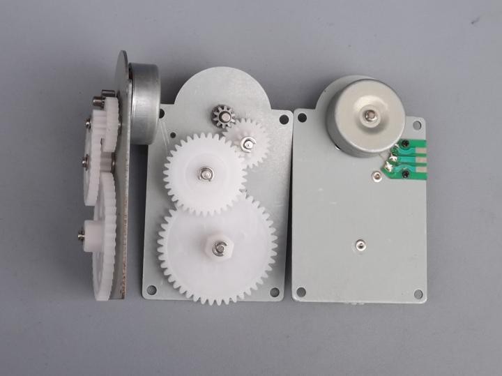
Quoted to be 23 times more efficient than solar power they say 5mins of crank time giving 1 hour of battery and it’s all packaged into a nice slimline case. The windup crank charging seems like an interesting alternative to solar, it could at least potentially solve the issue of charging at night and might also allow for quicker charging in emergency situations. After a search online we ordered some Micro Hand dynamo charger DIY hand generator brushless motors from Alibaba to experiment with:
![]()
![]()
They are currently being shipped and should be here any day.
JG
-
Experimenting with Bitcoin & Sensors
07/22/2016 at 15:38 • 0 commentsWe were really pleased to be announced as one of the winners of the Citizen Scientist challenge - thanks Hackaday! We're in the process of getting some cases 3D printed using some of the prize money, photos to follow.
We think the MyComm could be really useful for accessing remote data. "Internet of Things" and "Big data” have been super hyped but the truth is that all kind of data is being used to make intelligent decisions and that makes data valuable. For example, you have set-up a MyComm to get remote access to some exciting data, what if someone else would be willing to pay to access your data or you want to provide access to the data but want to cover the cost of the satellite communication?
21Inc is a company that has a vision to build a Machine-Payable web, built on Bitcoin. Their 21 Bitcoin Library is a Python library that makes it easy to make micropayments between a sender and recipient. Payments are made using Bitcoin and there are no transaction fees. The sender/recipients can be human to machine or even machine to machine and there is a marketplace where you can buy and sell bitcoin-payable APIs.
The idea of using micropayments to access remote data via a MyComm device sounds interesting so I followed this 21inc tutorial to build a Django project hosted on Heroku that can accept bitcoin-payable HTTP requests using the 21 and it works! Using the 21 CLI tool a “customer" can buy MyComm data by accessing an HTTP endpoint. The Django server confirms the micropayment then sends a message via the Iridium link to the MyComm which queries the sensor and sends the data back to the server, finally the server replies to the customer with the data value.
An interesting learning experience with lots of potential, please drop us a comment if you have any thoughts.
JG
-
Remote Data Logging - Citizen Scientist Entry
07/04/2016 at 08:02 • 0 commentsWith the power of the teensy micro-controller we have a large number of pins unused. This allows for a vast number of alternative functionalities for the MyComm device. A secondary functionality of the MyComm we envision is to be used as a remote sensor logger. The final device will have an expansion port that breaks out these unused pins and allows our users to connect a multitude of sensors to hack away as they please! This is particularly useful for remote location data logging. The SD card allows for a large data set to be recorded and the Iridium Modem allows the user to send back data in a number of ways; On request, on data change, at timed intervals or an external event. The two way communication of the device also means that an output could be triggered based on incoming messages. The application of this data logging is up to the user; With the open-source code they'll be able to write their own code to support the external devices as they see fit and link this to the on-board hardware of the device. We can see a number of uses for this such as;* Geigar Counter reporting
* Pressure recording
* Humidity recording
* Light level recording
* UV level recording
* Temperature recording
* Relay Control
* Remote Triggering of other devices
* Remote querying of current state
* Reporting and reacting to external input
We leave this functionality to your imagination. Have you ever wanted to record data for a couple of hours in the middle of nowhere? What if you were desperate to send some data back and you didn't have a phone connection? What if you were the first to witness a spike in radiation or UV level? What if you wanted to record data in a remote location, with solar available to keep the device alive, and have it report back when something interesting happens? These sorts of capabilities are possible.
We hope to support our scientists across the globe and make data logging that little bit easier!
JW
-
Iridium - Global coverage for only $6billion!
07/01/2016 at 09:48 • 0 comments![]()
Iridium Death Star! - Shows how the constellation can cover the globe
To ensure a global connection, MyComm uses the Iridium satellite service. The history behind Iridium is pretty interesting. The project primarily funded by Motorola was originally conceived in 1987 and became operational in 1998 for an estimated $6billion cost. The plan was to offer global communications to business men but the handsets ended up being the size of a brick and cost $3000, call charges were between $5-$30 per minute! By the time the complete constellation was operational the mobile infrastructure was being rolled out and although the coverage wasn’t global it was good enough and most importantly far less expensive. Nine months after going operational the company went bankrupt and at one point Motorola were going to de-orbit the whole network. Before that could happen a $35million acquisition in 2009 created a new company, Iridium Communications, Inc which is still trading today, providing extensive services to the DoD alongside global customers from the maritime, aviation petroleum and scientific industries.
![]()
Each satellite in the current network is approx 680kg, they have two 8m solar panels for power, as well as the main communications antennas there are gateway antennas for communication with the ground stations and crosslink antennas to communicate to other satellites in the constellation. For much more technical details see here.
![]() The Iridium satellite constellation consists of 66 satellites in a low earth orbit of approx 485miles. The satellites orbit from pole to pole with approx a 100 minute orbit time. There are 6 orbital planes with 11 satellites in each plane. The orbit design provides coverage over the planets entire surface.
The Iridium satellite constellation consists of 66 satellites in a low earth orbit of approx 485miles. The satellites orbit from pole to pole with approx a 100 minute orbit time. There are 6 orbital planes with 11 satellites in each plane. The orbit design provides coverage over the planets entire surface. Currently Iridium is in the process of developing it’s second generation constellation called Iridium NEXT which aims to provide more bandwidth and higher speeds - this time they got a bargain with the estimated cost only $2.9 billion.
JG
-
Free RTOS Success!
06/16/2016 at 09:57 • 0 commentsI was able to add the Free RTOS to the GUI MyComm code. The main GUI runs in a dedicated task and a secondary task is running which prints out memory usage details. The standard Arduino "Loop" function also runs as an "idle" task. When nothing else is running then the Arduino Loop function is called. The Setup looks like this:
    xTaskCreate(vMainGUITask,
    "Task1",
    configMINIMAL_STACK_SIZE + 10500,
    NULL,
    tskIDLE_PRIORITY + 2,
    &gui);

    // create print task
    xTaskCreate(vPrintTask,
    "Task2",
    configMINIMAL_STACK_SIZE + 120,
    NULL,
    tskIDLE_PRIORITY + 3,
    NULL);

    // start FreeRTOS
    vTaskStartScheduler();
"Task 1" is the main GUI code. It has a larger configured stack size ("+10500") due to the size of the code and the fact it loads images. This may be reduced in the future depending on how testing goes.
"Task 2" is the debug printing task. It has a smaller stack due to the lack of functionality and low memory requirements. You'll notice it's priority is "+3". This means it is a higher priority than Task 1. The advantage of this is that the debug print task will always be run no matter what state the GUI task is.
Initially I had the GUI task as the highest priority; My thinking was I don't want anything to interrupt the users inputs. However, this meant that I had to "release" the task in order for the other tasks to get any run time. There are number of infinite while loops within the GUI code when it waits for user input. Placing a "taskdelay" within each section of the code would allow the other tasks to run but would be cumbersome and counter intuative to what I'm trying to achieve with FRTOS. For now I've lowered the priority in order that the debug tasks runs automatically without me having to decide when; This may change in the future depending on testing. For now the GUI is showing on the screen and I see no lag or degradation in user experience since changing over to FRTOS.
The beauty of Free RTOS is that I can make a dedicated task, test the code and then implement it by calling a new task. There's no need to work out when the new code must be called or any timings to adjust. Memory management is still a consideration that I'm keeping an eye. The flexibility of Free RTOS showed it's self when I started work on communicating with the iridium modem. There's a simple library (IridiumSBD) available that handles the communications protocols so within 5 minutes I had a task running that queried the Modem's signal strength. Made a global variable and now the top section of the display shows the current signal strength. Easy! It's going to take so more work to get messaging up and running but I'm not daunted by this.
*I'll add an image once my wifi is more stable
JW
-
Trouble Shooting Communication Protocols! - Hours of f(rustration)un?
06/08/2016 at 09:25 • 0 commentsI would like to think I am becoming an "experienced" user of Serial communications. I have written my own packet based communication protocol for Arduino-Arduino and Arduino-Pi communications and worked with a number of different Serial devices (IMUs, Compasses, GPS etc). I also know what to do when dealing with RS232, RS422 etc. However, every device is different and every one of them has their quirks. Sometime's what works in the past trips you up in the future.
I've started working with the Rockblock Mk2 Iridium modem breakout. It works on an "AT" command system similar to older modems. There is a very well documented Arduino library available from the same person that did the Tiny GPS library (excellent library by the way). Reading the data sheet of the Rockblock states that an "AT" command with a newline will get a response "OK". Great, that's an excellent starting point to make sure everything's working. Nice and simple. I don't have an FTDI Serial-USB cable handy but I do have a Teensy 3.1 which has dedicated hardware serial ports. I can use it to pass data from the pc to the Rockblock and print back what it gets back. Easy. So I programmed the teensy with the following code:
#define IridEnablePin 23

void setup()
{
	Serial.begin(9600);
	pinMode(IridEnablePin, OUTPUT);
	digitalWrite(IridEnablePin, HIGH);

	delay(2000);
	Serial.println("MyComm Iridium Pass Through Test");

	Serial1.begin(19200,SERIAL_8N1);
}


void loop()
{

	while(Serial1.available())
	{
		char c = Serial1.read();
		Serial.print(c);
	}

	if(Serial.available())
	{
		while(Serial.available())
		{
			char c = Serial.read();
		        Serial1.println(c);
                }
	}


	delay(100);
}
Baud Rates? Check
Wiring? Check
Power? Check
PC Send "AT" and include new line.... Nothing. No response. I spent a total of 5 hours checking wiring, datasheets, reading forum after forum. There were mentions of tieing flow control signals to ground to make sure it wasn't flow control related. I tried reversing TX/RX more times than I can count. I tried changing my power supply and usb cables. Still nothing.
Then it hit me. "\n" (newline) is a very specific character and I might not be sending it correctly. So I went even more basic:
Serial1.println("AT");And low and behold! "OK" was my reply. What I thought was a simple Serial pass through hadn't worked at all. So there we go, many hours wasted but I'm now very familiar with the Rockblock's power up sequence, wiring and general AT command options. My fixed pass through code looks like this:#define IridEnablePin 23 void setup() { Serial.begin(9600); pinMode(IridEnablePin, OUTPUT); digitalWrite(IridEnablePin, HIGH); delay(2000); Serial.println("MyComm Iridium Pass Through Test"); Serial1.begin(19200,SERIAL_8N1); } boolean printAfterDelay = false; void loop() { while(Serial1.available()) { char c = Serial1.read(); Serial.print(c); } if(Serial.available()) { delay(100); String NewCommand = ""; while(Serial.available()) { char c = Serial.read(); if(c != 'n') NewCommand += c; } NewCommand.trim(); Serial1.println(NewCommand); } if(millis() > 180000 && !printAfterDelay) { Serial.println("180 Seconds have passed. Iridium should be online"); printAfterDelay = true; } delay(100); }Always new lessons to learn with every device,JW
Update; After speaking with Elliot Williams from Hackaday I was told that "println" actually adds a carriage return as well as a linefeed (\r\n). So I thought; what if the Datasheet is wrong and the Rockblock actually requires a carriage return as well as the linefeed? Turns out it does! My original pass through code works when I end the PC command with carriage return + linefeed! So there you go, don't always take a datasheet's word as golden!
-
Programming - Multitasking Decision
06/07/2016 at 13:35 • 0 commentsInitial Discussion
Multitasking is obviously vital to pc day to day use. Programs, or tasks, appear to run simultaneously to the user which allows them to run multiple programs even with cross-interactions between them seamlessly. From the processors point of view it's a little bit more complicated. The appearance to the user is that all tasks are running at the same time but this actually untrue in a "single core" environment. This task handling is done by the "OS". The OS keeps track of the running tasks and decides what task gets run at any given moment then switches to the next priority task. Obviously Windows won't run on such a small processor as an Arduino micro-controller but there are real time operating systems available that create the same "task handling" environment which allows for easy multitasking. This is important to our application because the MyComm will need to handle multiple tasks at the same time. There is the screen and gui to handle but also the Iridium modem. The iridium modem communicates over a standard serial port which will need managed. New incoming messages may appear and we can't have the gui shut down while we handle this incomming message. The handling of the Iridium can be thought of as a "background task"; One that the user is essentially unaware off but still a vital component for the MyComm to work. The diagram below highlights the idea behind multitasking:
![]()
Free RTOS
Taking advantage of the Arduino echo-system and vast support for the Teensy 3.x meant that finding a free open source real time operating system (RTOS) was a quick google away. FreeRTOS has been ported for Arduino - here - by a user known as Bill Greiman. I found his post through the Teensy forum - here - so I know the Teensy is supported. There is a wealth of information available on Free RTOS and a few good blog posts around too. Getting the library to play ball with my IDE was a bit difficult at first. I eventually went into the specified RTOS Arm folder, ripped out the .c and .h files and bundled everything together into a folder setup that would play nice with Arduino + Atmel Studio + Visual Micro. It was a bit frustrating but I was able to get an example file running after a couple of hours.
The Free RTOS works like a standard Arduino library so I can still use the general core Arduino libraries and functions. It allows the user to define tasks and the Free RTOS library handles the switching between tasks and general mangement. Care has to be taken with memory usage so I'll need to keep an eye on this.
The Plan
I've branched off my git code for now and I have a basic test setup running Free RTOS. My plan is to now port over the current GUI code and have it running fluidly inside a single task. At the same time I'll have a second "debug" task running that prints out details such as memory usage and to ensure the gui task isn't hogging all of the reasources. There's a good basic example in Bill Greiman's port library that blinks an led in one task and prints out debug data in another so I'm using this as the starting point for my code.
JW
-
Display Programming (2) - Video Update
06/07/2016 at 08:44 • 0 commentsA new video update of the MyComm interface. Mostly the interface has been tidied with new icons and a clear menu system. A lot of work has been done on storage. It's quite tricky working with large amounts of characters for text. Contacts and messages can take up a lot of space. Luckily we have an SD card built in to store all this data. The SD card library for Arduino is pretty good but deciding on file formats and methods of storing/retrieving data takes some work.
JW
-
Power to the people
05/27/2016 at 16:18 • 0 commentsOne aim of the project is to create a device that is portable, so we know we need a battery. But batteries have a tendency to be flat just at the time we need them most so we also want to make it possible to charge the battery via solar to give as much chance to send that crucial message as possible. There's a lot of design decisions to made - what type of battery? What capacity do we need? How can the battery be charged using solar? What are the trade offs between solar size and time to charge? Can we actually get any useful charge from a solar cell in Scotland?! As we work through these questions we'll update the logs to document our thought process and choices. Please feel free to offer any comments or advice.
-
Enclosure Design (1) - Iterative Designing
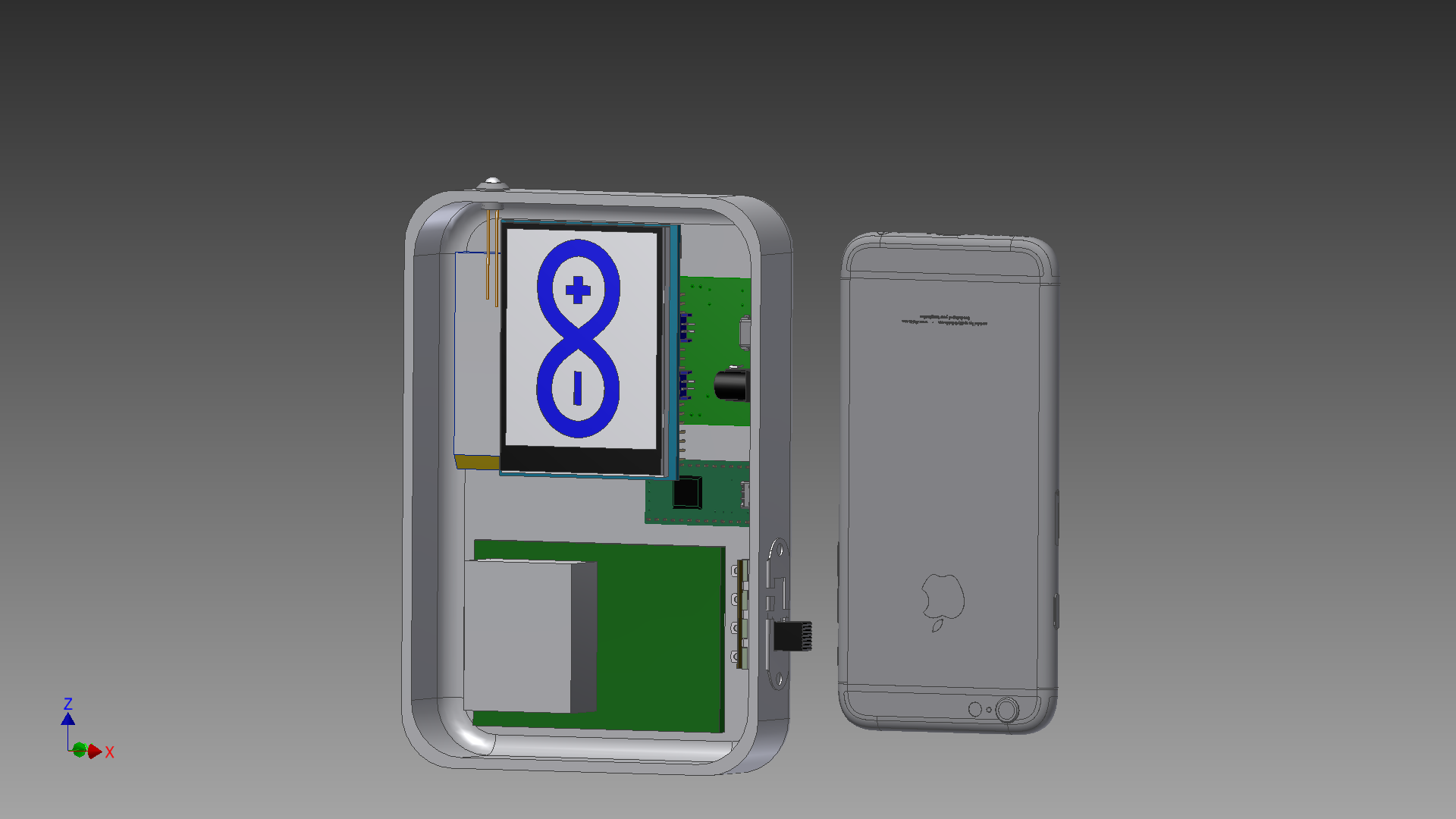
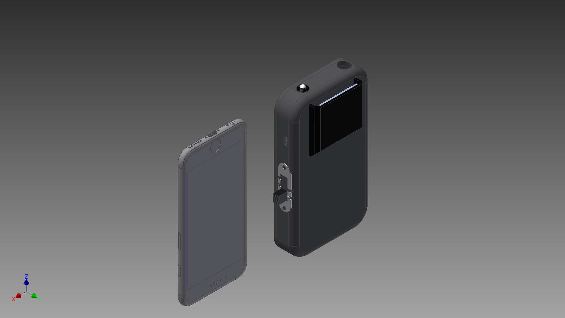
05/26/2016 at 11:05 • 0 commentsWith the coming together of better part selection it was possible to look at iterating the initial prototype designs. Using cad files and mockups of the current component list; Screen, MCU, Power etc. The v2 prototpe below was created (Iphone for comparison);
![]()
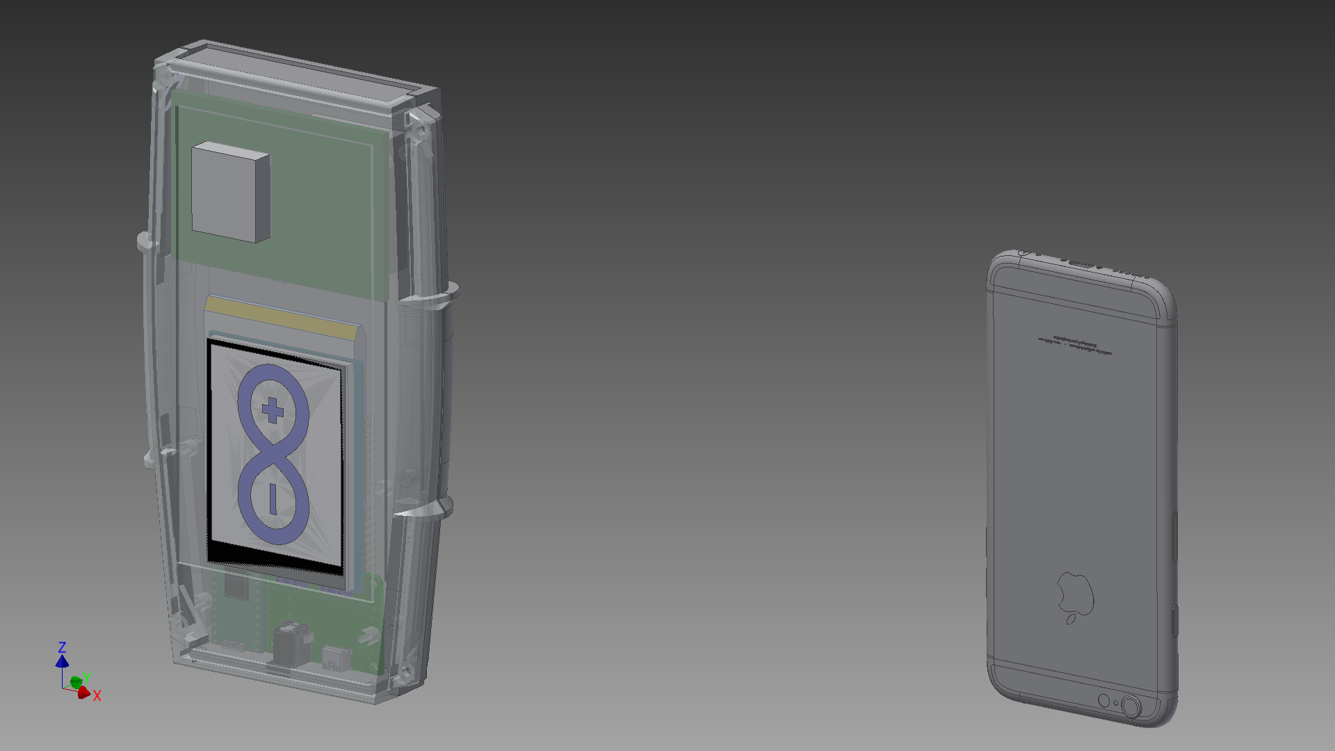
This design was based on a simple 3d printed case. No cover is shown just now so that we can see the layout of the components clearly. While 3d printing is useful, I also had a look around for an off-the-shelf solution. Off-the-shelf can be a cheap and quick way to get a prototype enclosed but generally there can be a lack of space so choosing the right one is vital. I made a layout mock up using the 66 Series Grip Cases from CamdenBoss;
![]()
The prototype is coming together. It's also interesting to consider a general "final product" design and what form that will take. A few discussions have resulted in 3 possible directions. All the below are based on a custom pcb instead of off the shelf components;
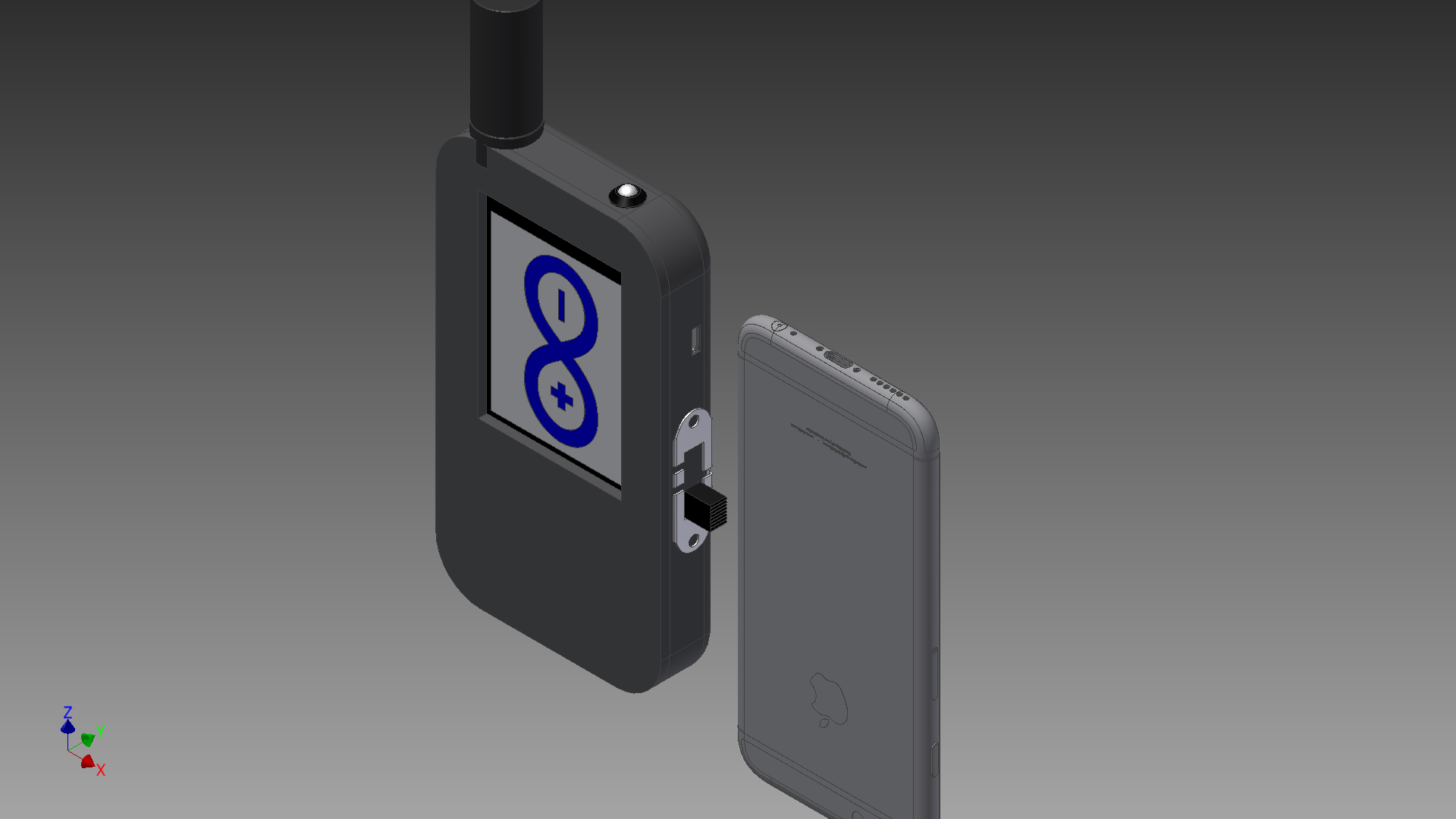
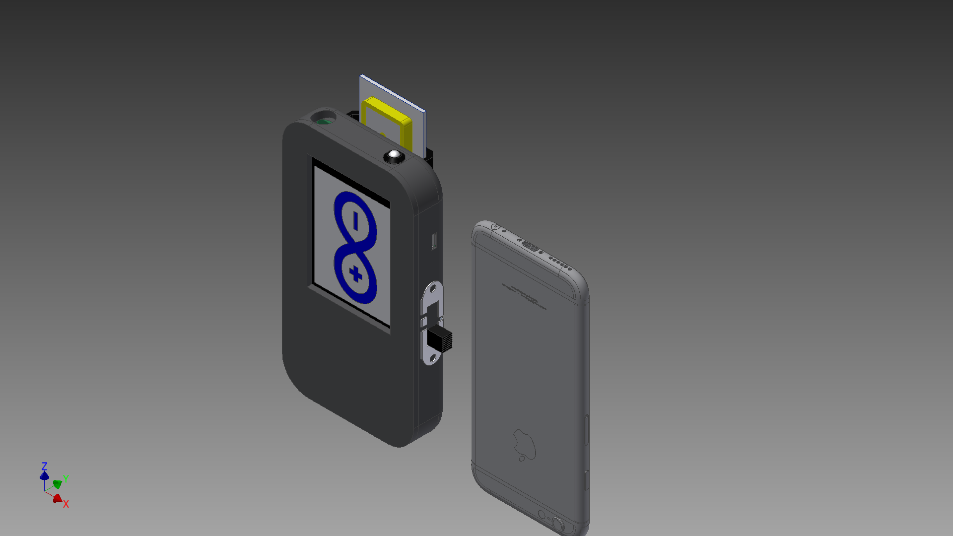
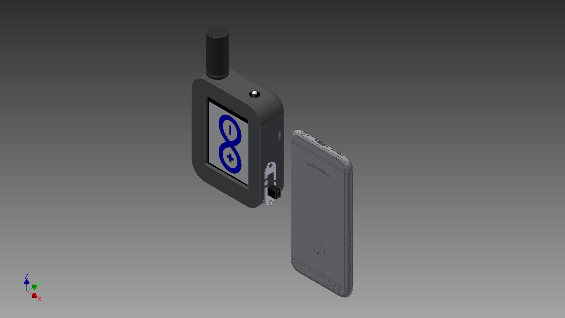
The design is very similar to standard "sat phones" with a helical antenna ("Rubber duck") on the top. The helical antenna is a point of conflict within the team. From an engineering perspective it gives good signal quality, doesn't take up space internally and isn't generally concerned with its position relative to the sky. However, other points have been made; It's a point of fragility on the device and easily broken, it's considered "ugly" compared to other devices and it adds to the overall size of the device. The other option to a helical antenna is a patch antenna. These require a general position relative to the sky and can't be placed inside the enclosure due to interference from the screen blocking signals. There might be one way around this though;![]()
![]()
Placing the patch antenna on a "pull-out" mechanism would allow for the antenna to be hidden away when not in use. This lowers the height of the device but adds a little bit of bulk on the back.![]()
Finally, there's the question of thickness over height. By fitting all of the components behind the screen we can reduce the profile of the device at the cost of adding general thickness. Bringing a total thickness to 30mm - whopping in smartphone standards but still very practical;
The final design will likely changed as we progress further but creating a target goal allows us to keep focused and make design changes while considering the effects on a potential final product. Compromises must always be made at some point.![]()
I'd appreciate any feedback on what people think of the overall designs, do you have one that stands out as a favourite?
JW
MyComm
A portable, solar powered, handheld device that provides truly global messaging when you have no alternative.


 The Iridium satellite constellation consists of 66 satellites in a low earth orbit of approx 485miles.