John Grant
-
Build Instructions (2) - Hardware Preperation
09/23/2016 at 11:25 • 0 commentsThis log details the Hardware preperations required for building the MyComm device using the off-the-shelf parts for Prototype 1.
Hardware Preperation:
3d Print the case parts: Case Design - Front Cover Screen - RockBlock V0.1.stl, Case Design - Base V0.1 - Rockblock Support.stl
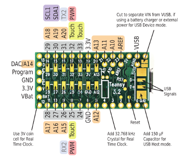
The stock Teensy 3.2 connects Vin with VUSB. This means that the Teensy can't be powered by Battery and re-programmed at the same time. If you want to be able to reprogramme the Teensy under battery power you either need to cut the 5V line on a usb cable or cut the Vin-VUSB trace on the underside of the Teensy:
![]()
Veroboard Build:
Follow the wiring schematics in order to build a veroboard to attach devices. This is my first run at building the MyComm prototype so there may be easier ways to achieve the build but this is the documentation first build;
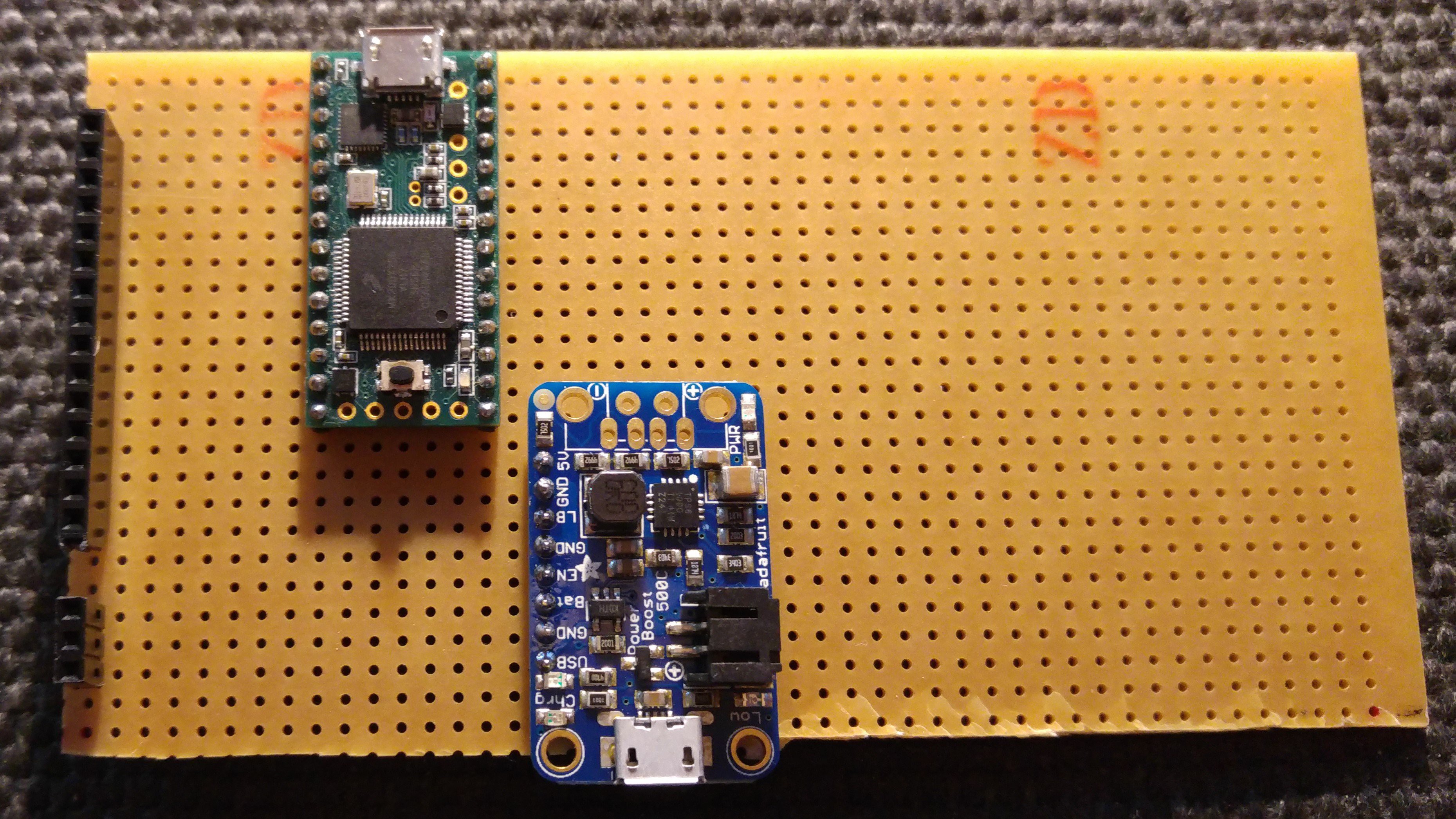
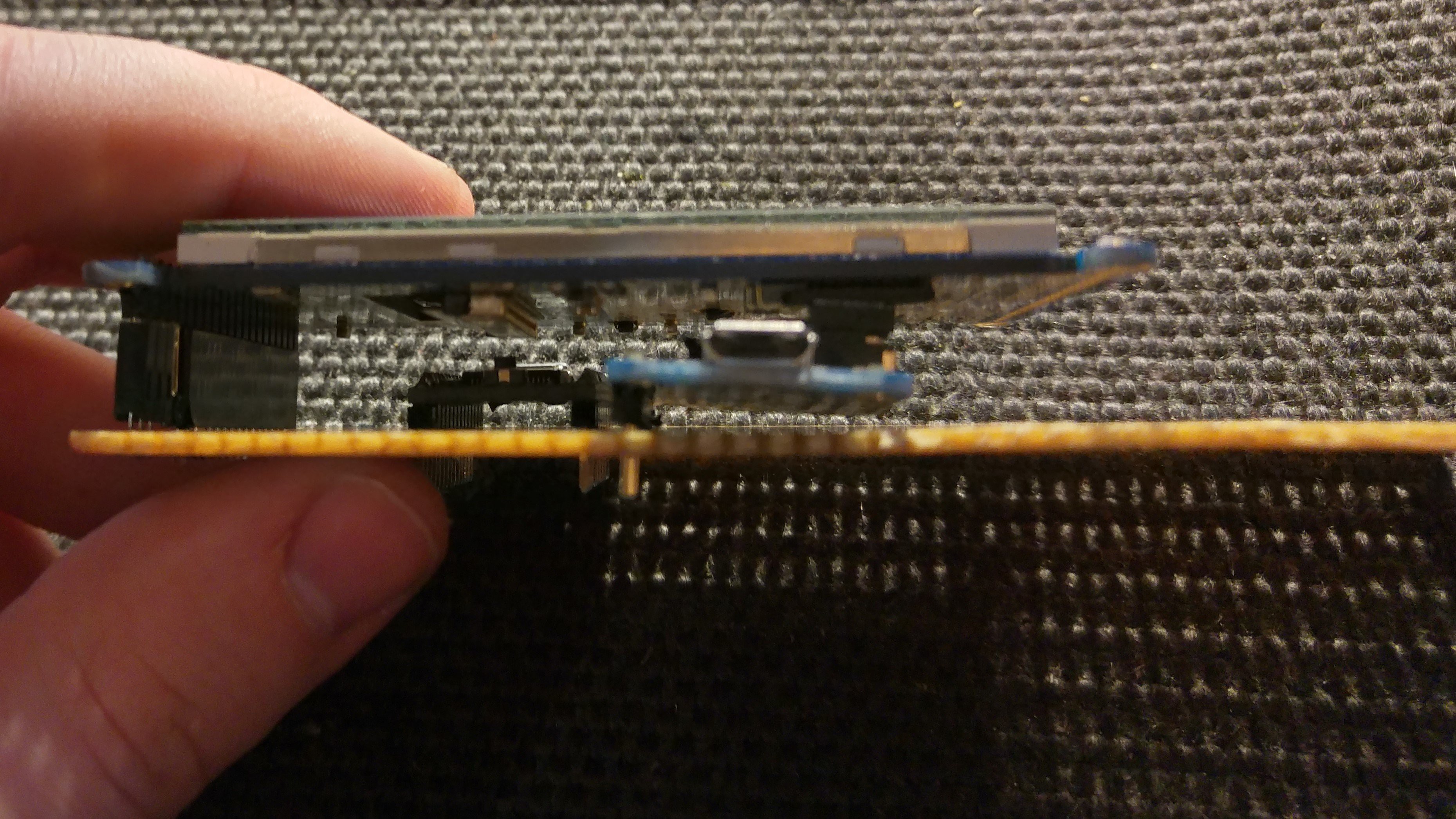
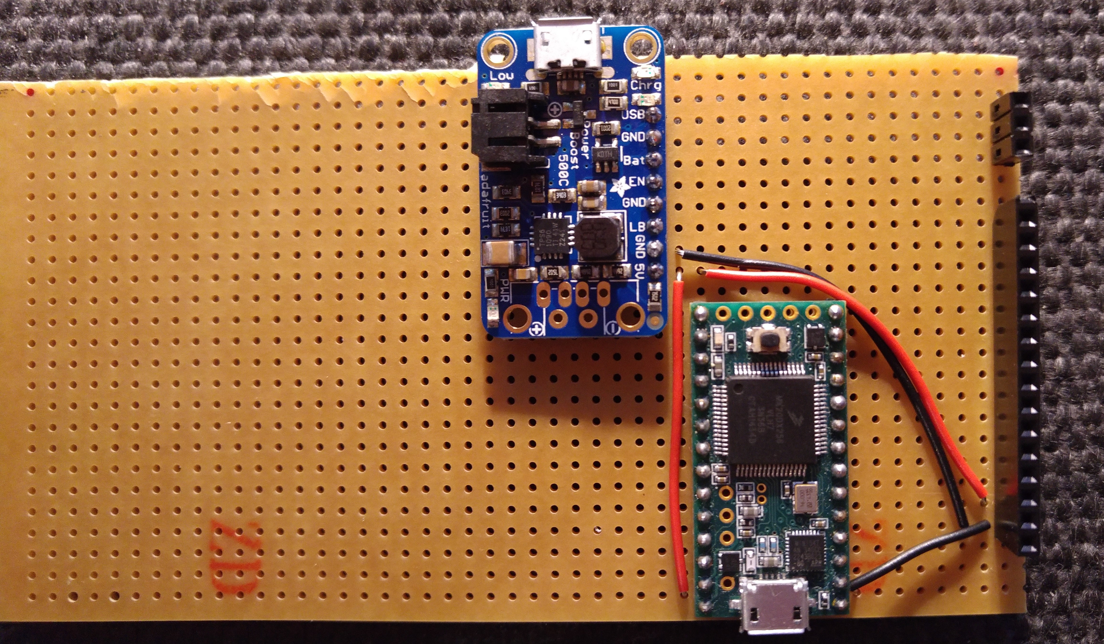
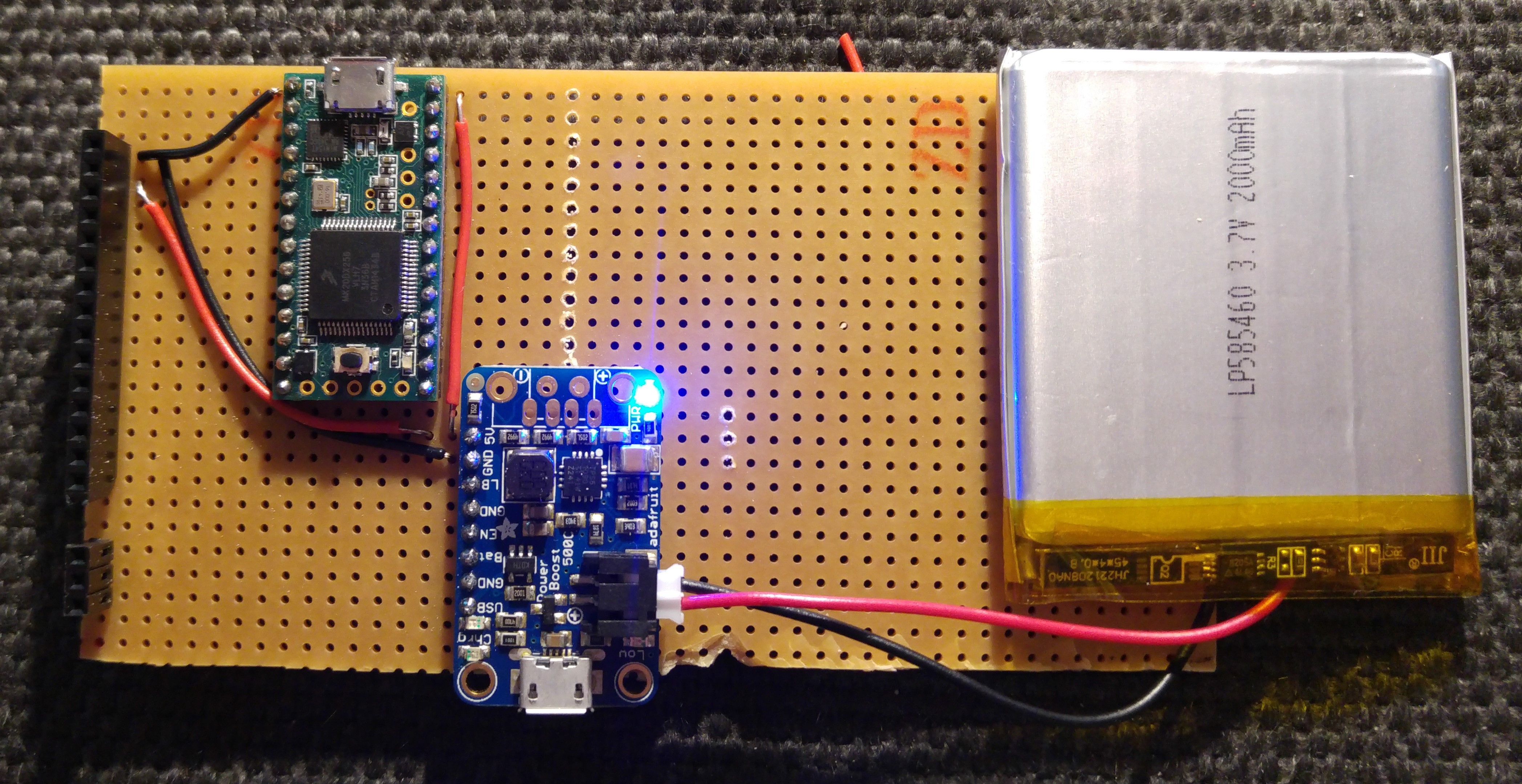
- Step 1: Lay out the Teensy, Headers for the Screen and Charging Circuit.
Check with screen going over the top of the other parts:![]()
![]()
![]()
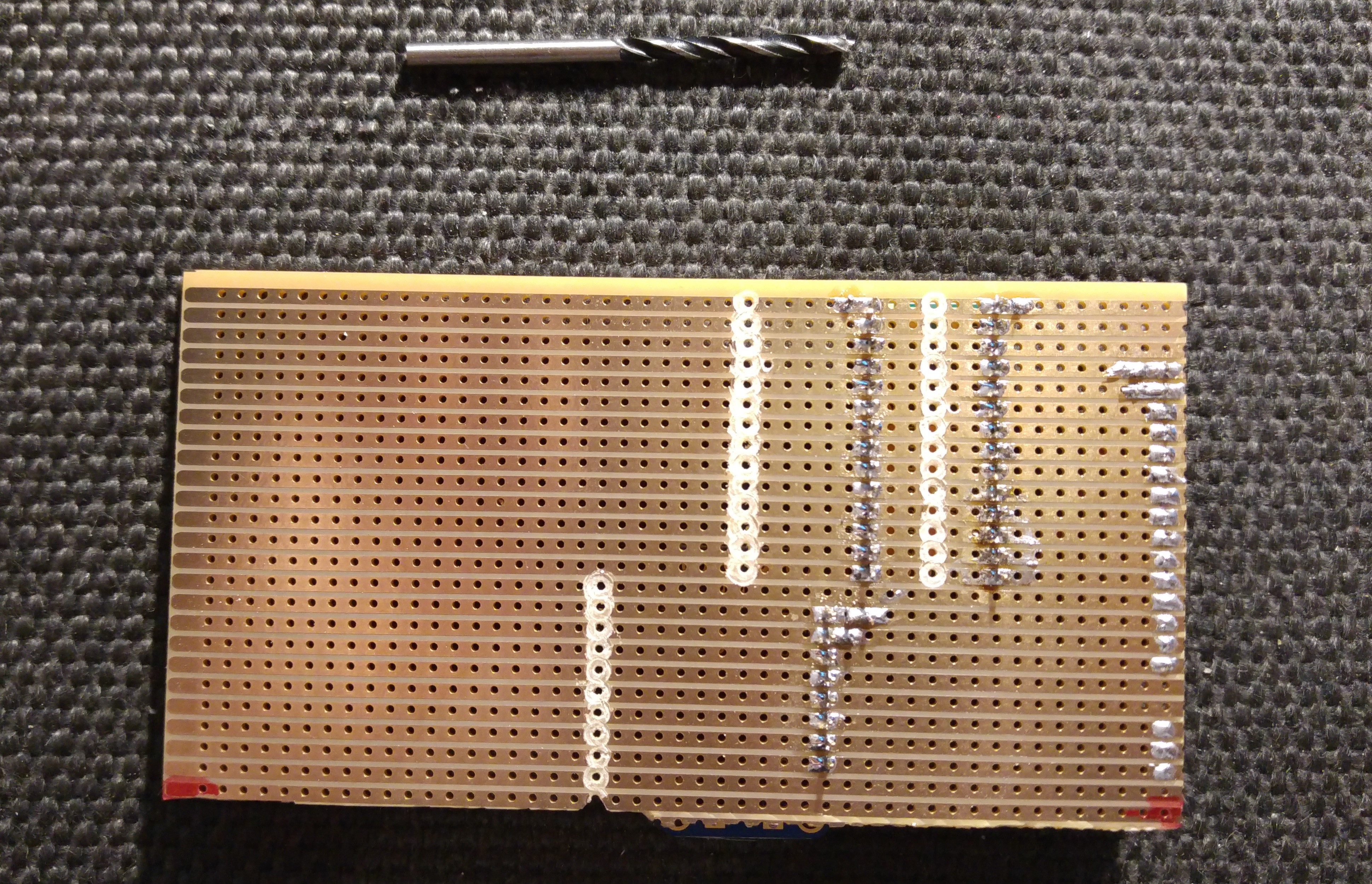
- Step 2: Layout and solder power connections for the 5v Output. I find the easiest way to break the veroboard column connections is with a medium size drill bit in my hand drill.
![]()
![]()
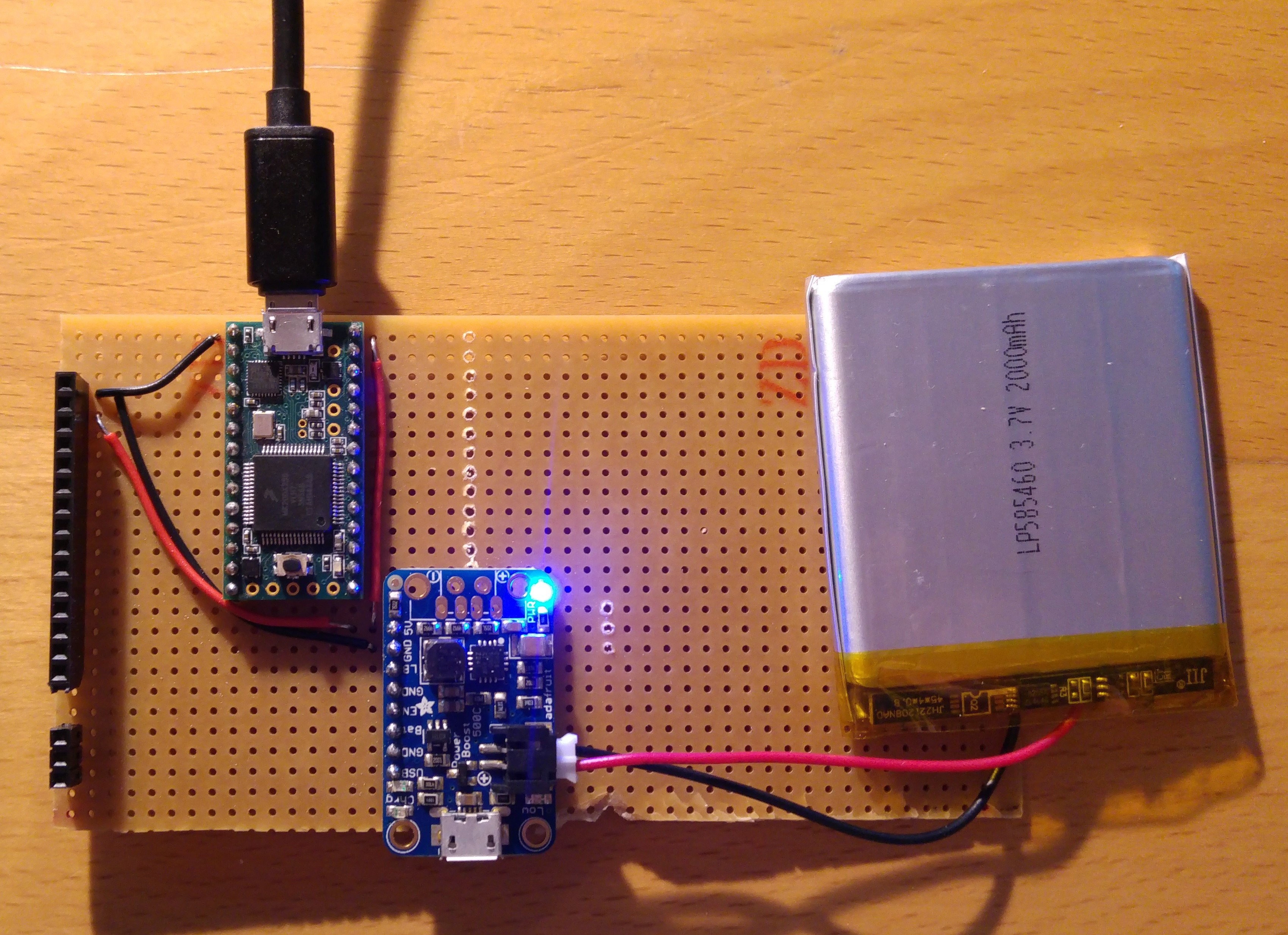
- Step 3: Test battery power with the Teensy. If you've completed Build (1) then the Teensy LED should blink steadily with the battery connected. If not, check all wiring before trying to connect the Teensy to the PC.
![]()
- Step 4: Reprogram the Teensy with the MyComm code (Ensure your Vin-VUSB connection has been cut!). See Build(1) for further details.
![]()
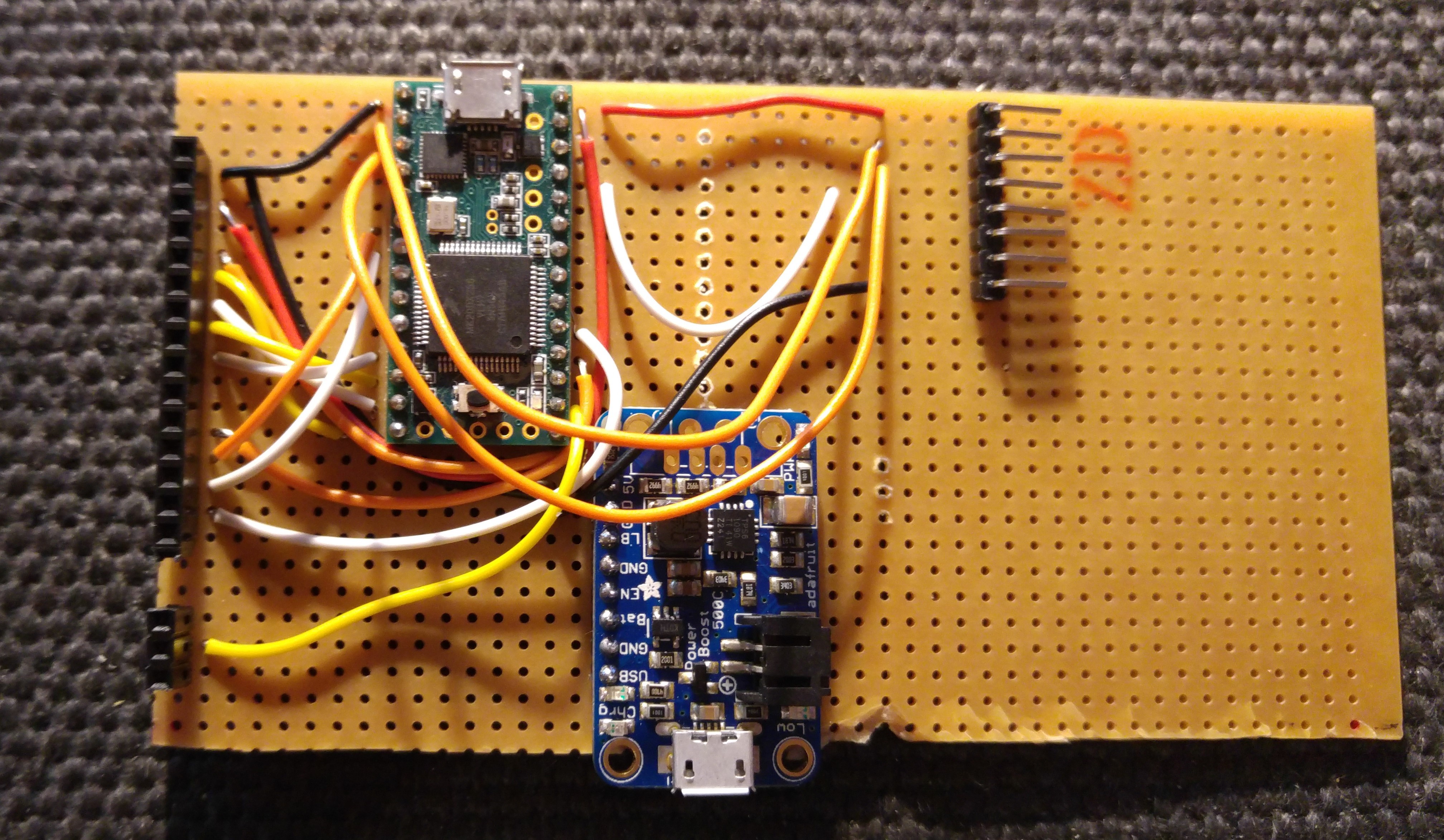
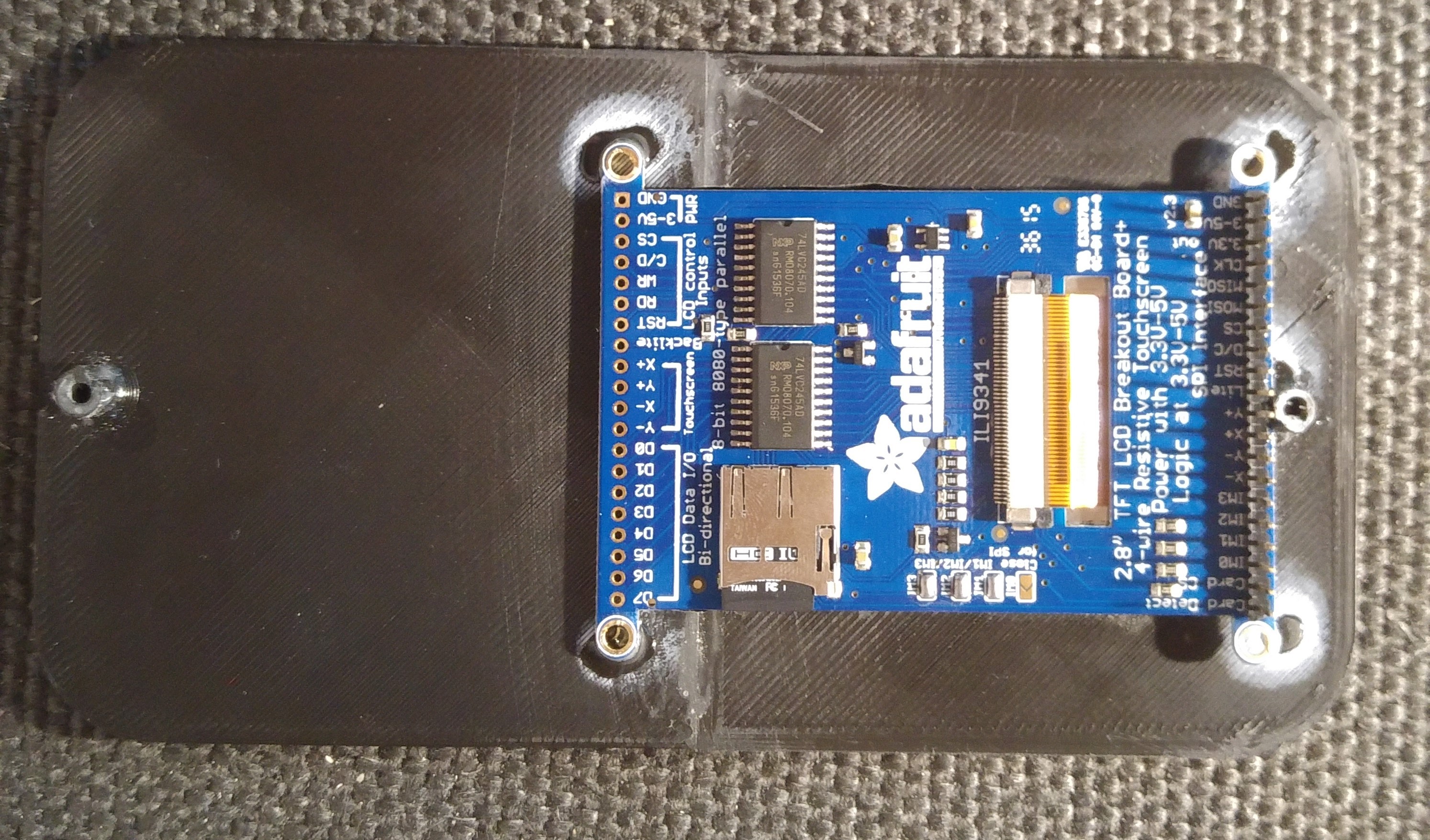
- Step 5: Lay out the wiring for the SPI to the screen/SD
![]()
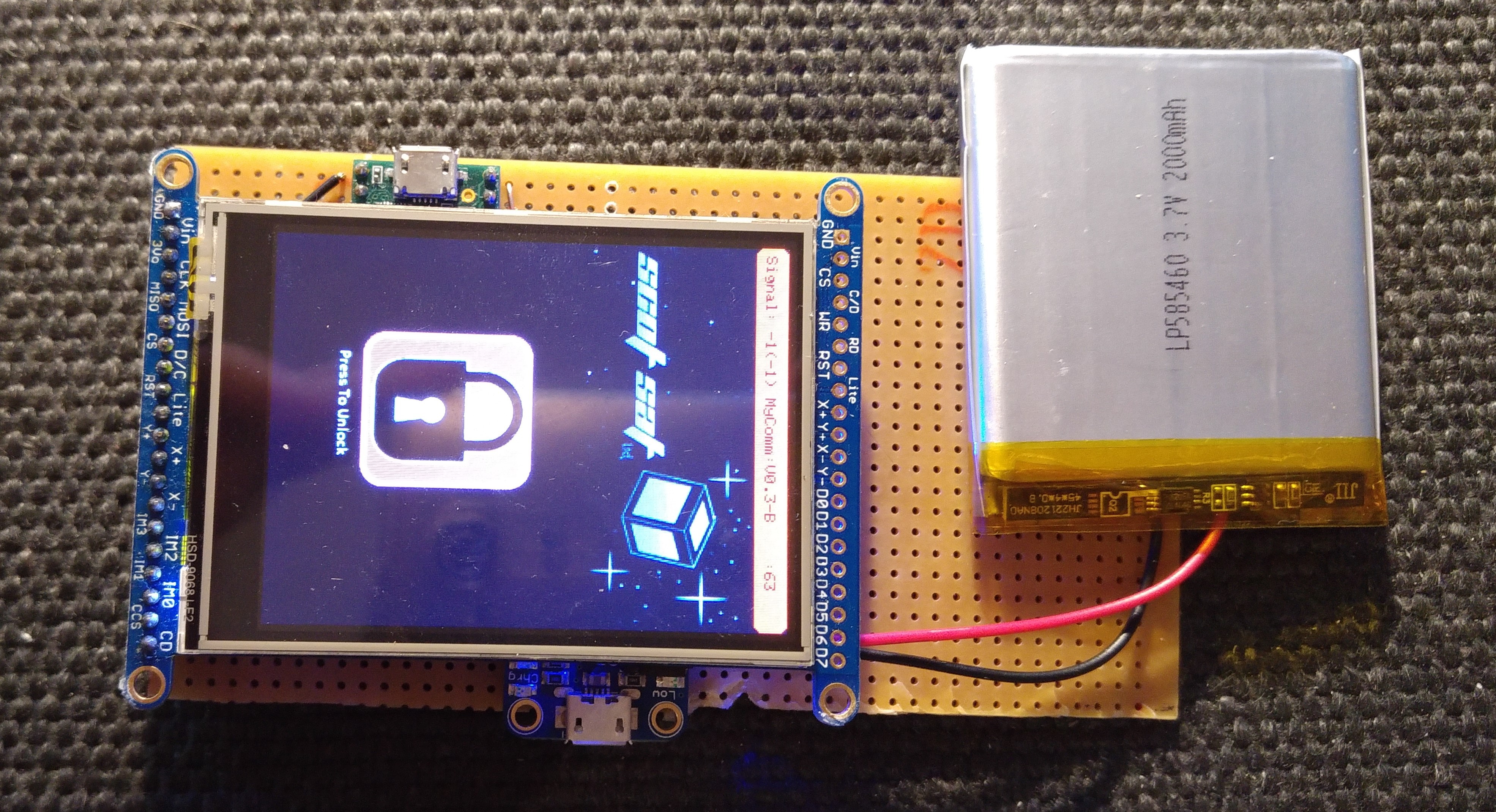
- Step 6: Insert your blank SD card into the slot on the back of the screen then test the screen with the battery connected. You should see the MyComm interface.
![]()
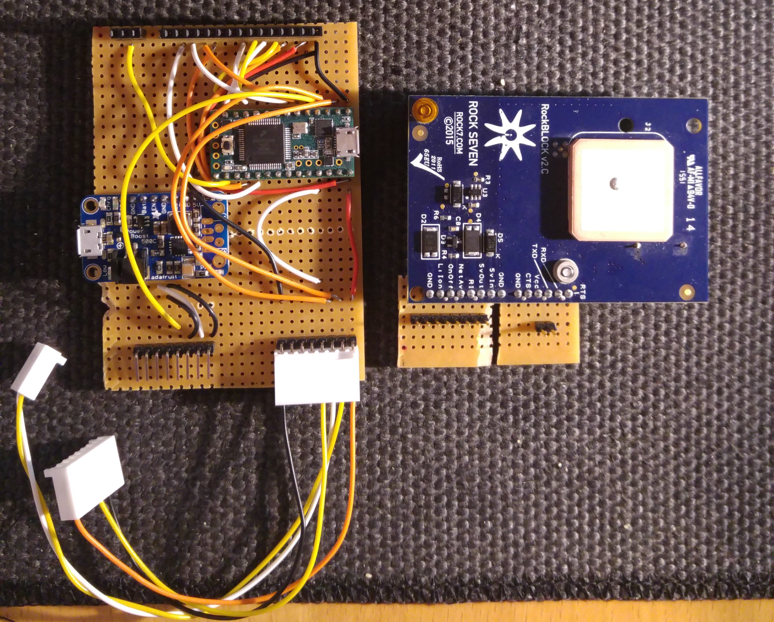
- Step 7: Setup wiring connections for the Rock7 Rockblock. I used right-angled header pins but I would have preferred to use a Molex right-angled connector to ensure the connections are solid.
![]()
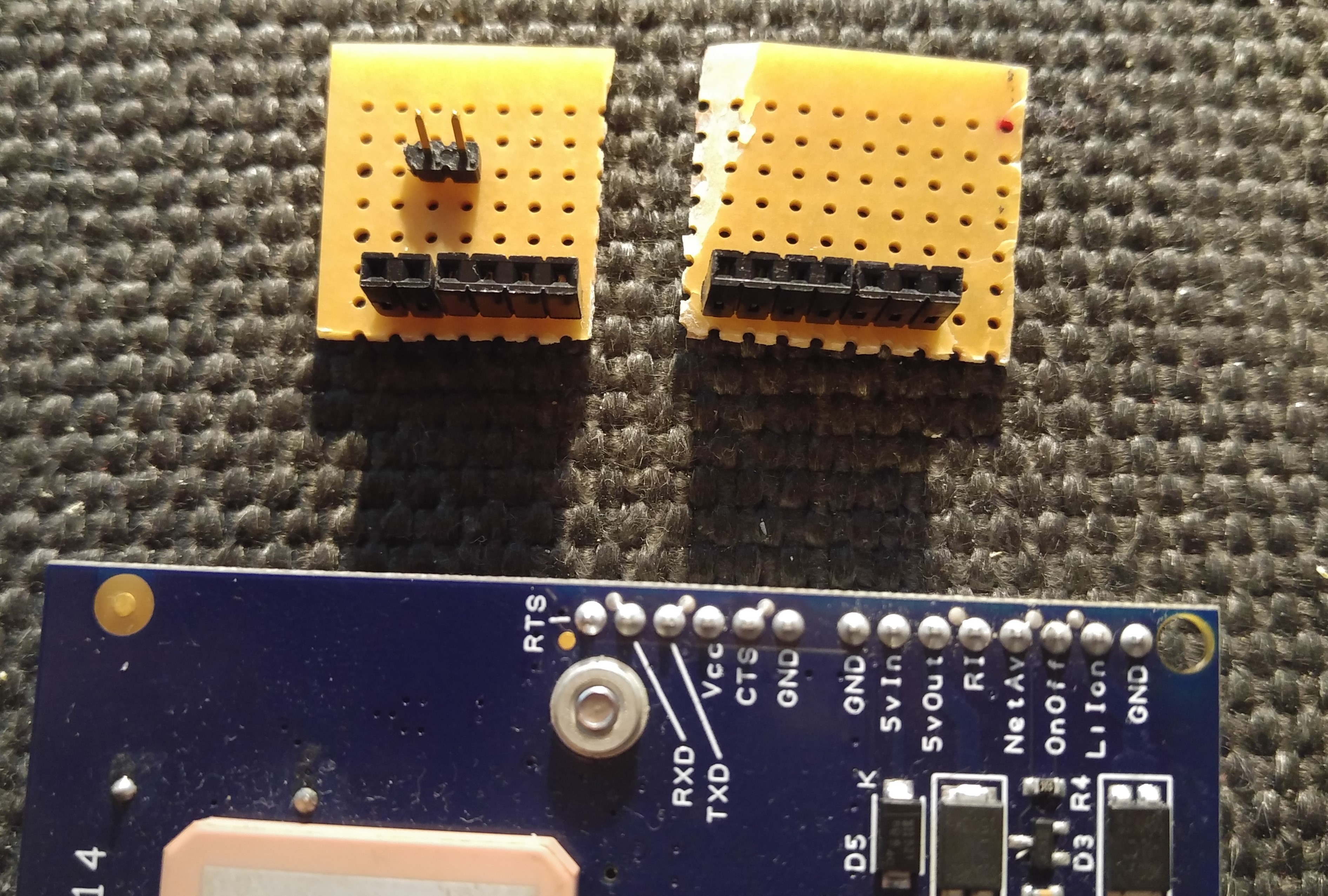
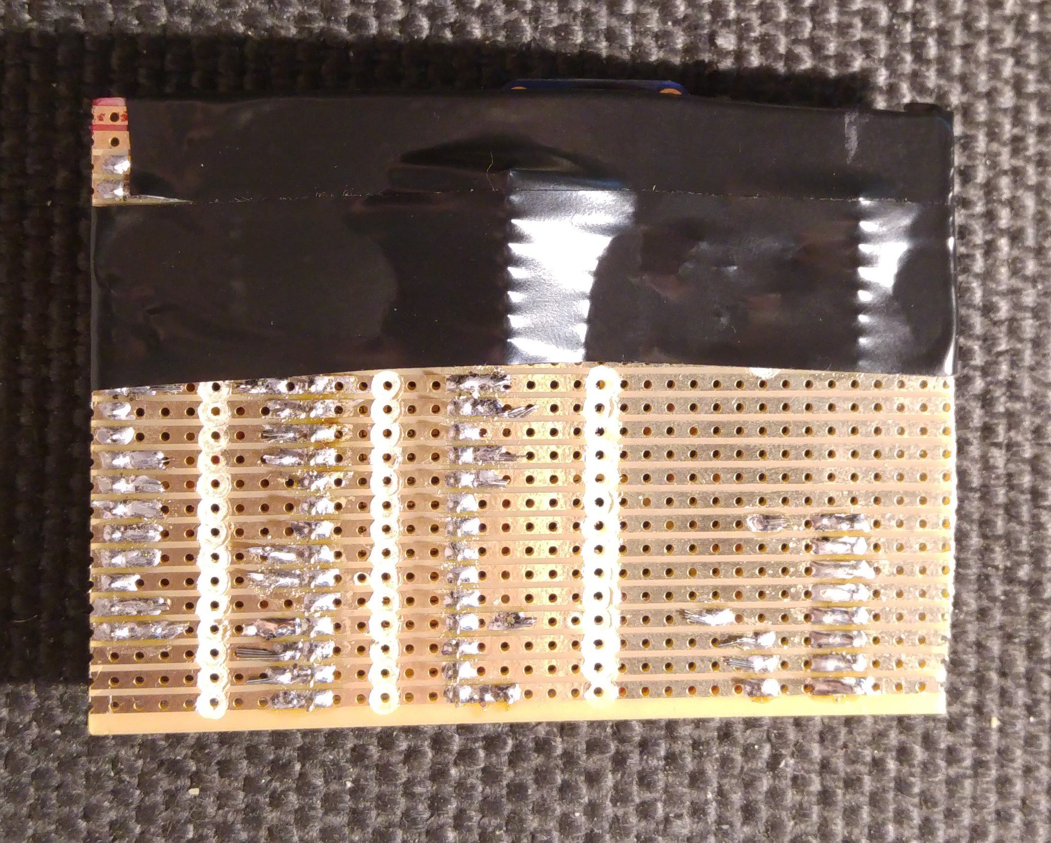
- Step 8: The Rockblock needs to have the patch antenna facing up so that when the MyComm is on the base it can still transmit. For this I used some veroboard to provide connection points for the wiring.
![]()
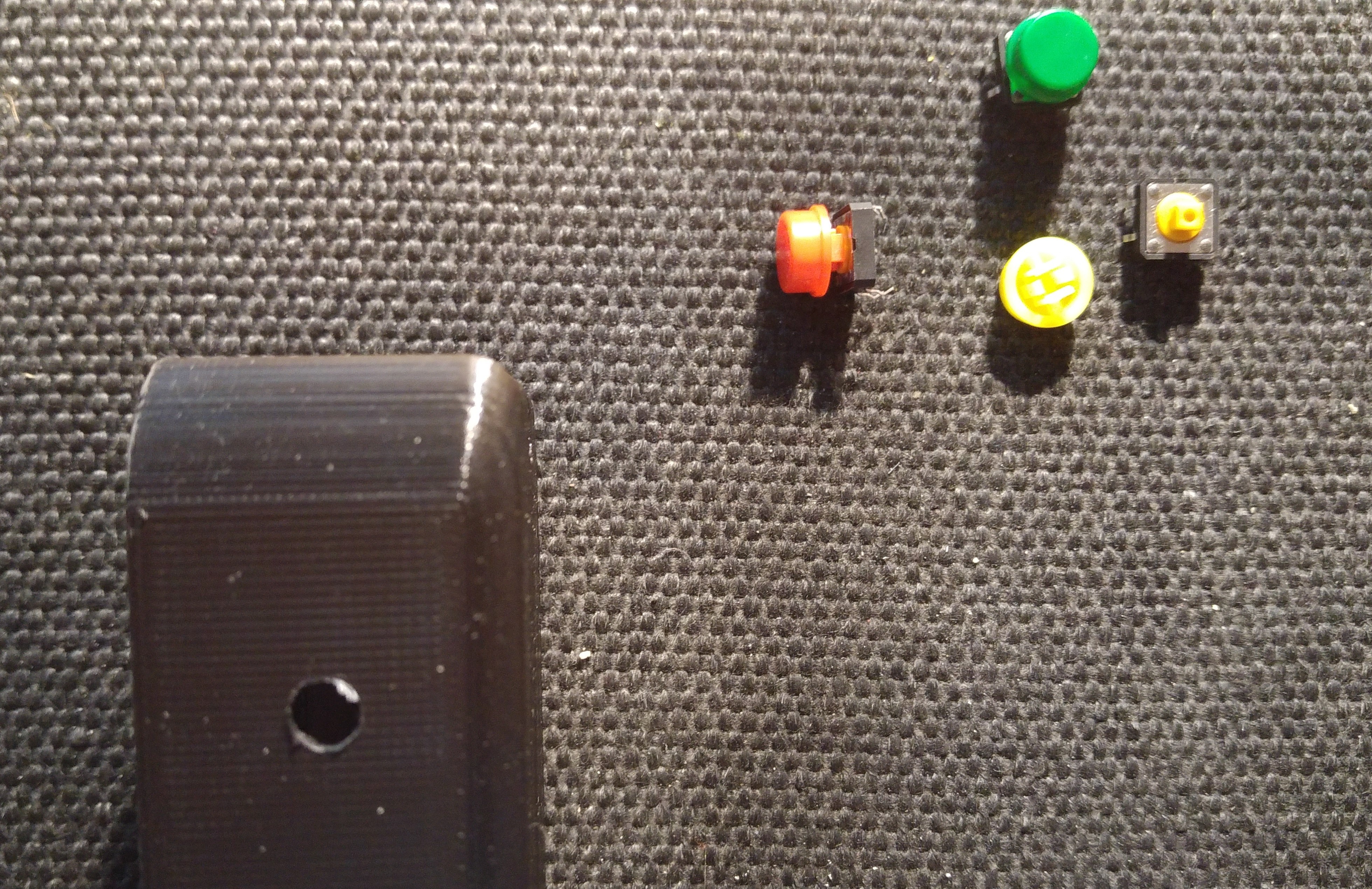
- Step 9: Setup wiring for Button and LED Connections
![]()
Assembly:
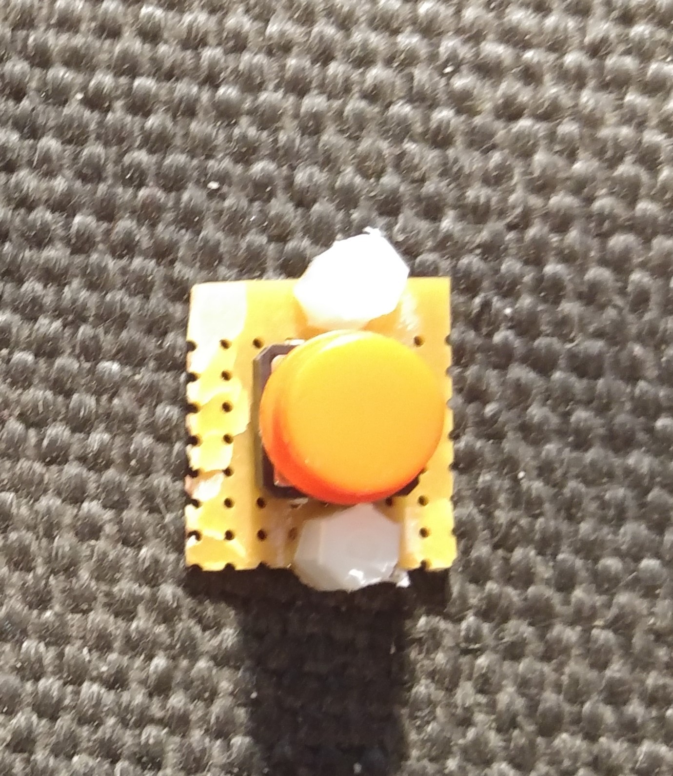
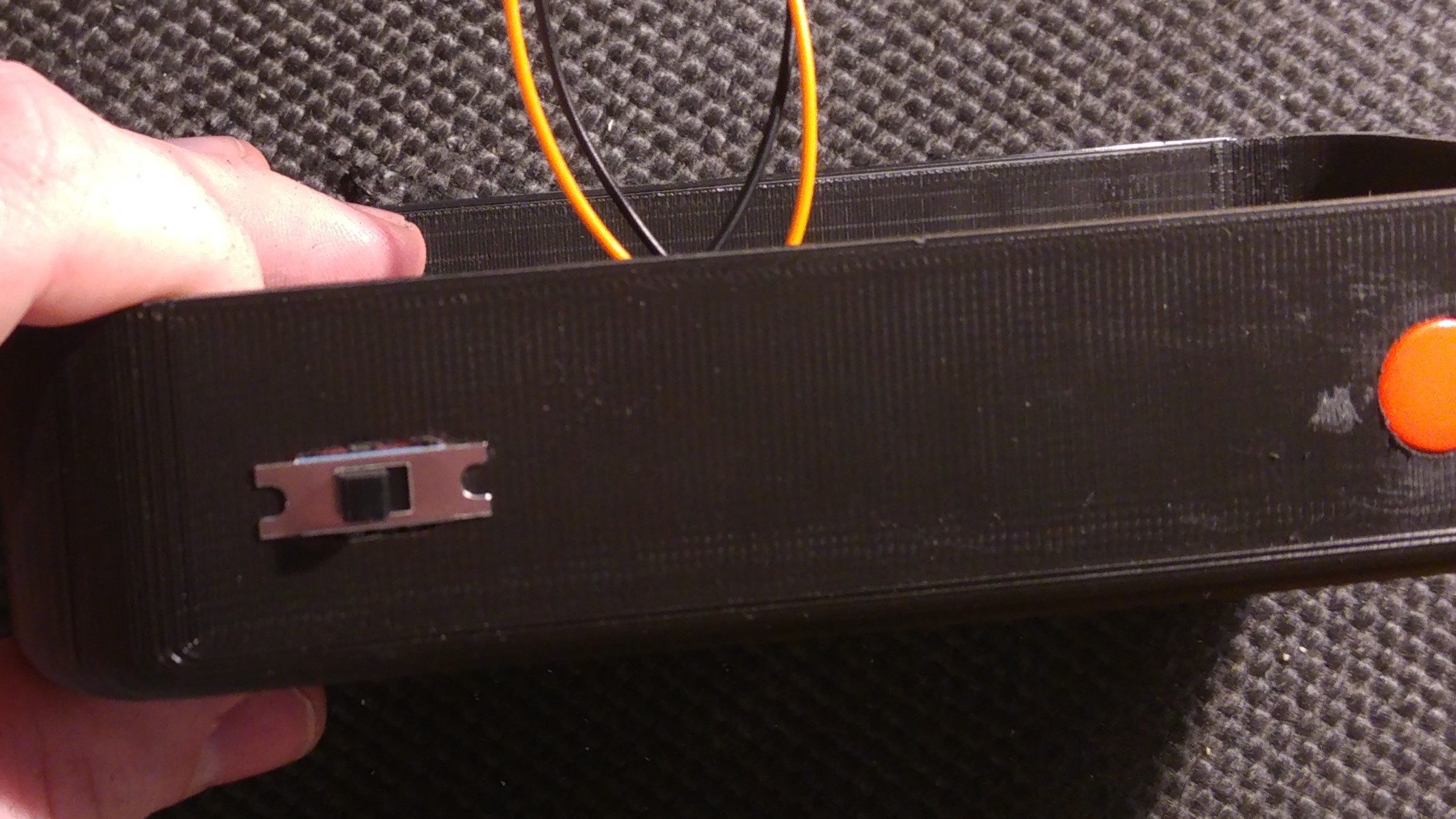
Step 10: Mount Button and LED to the Box
![]()
I used a piece of veroboard in order to mount the button to the wall of the box
![]()
![]()
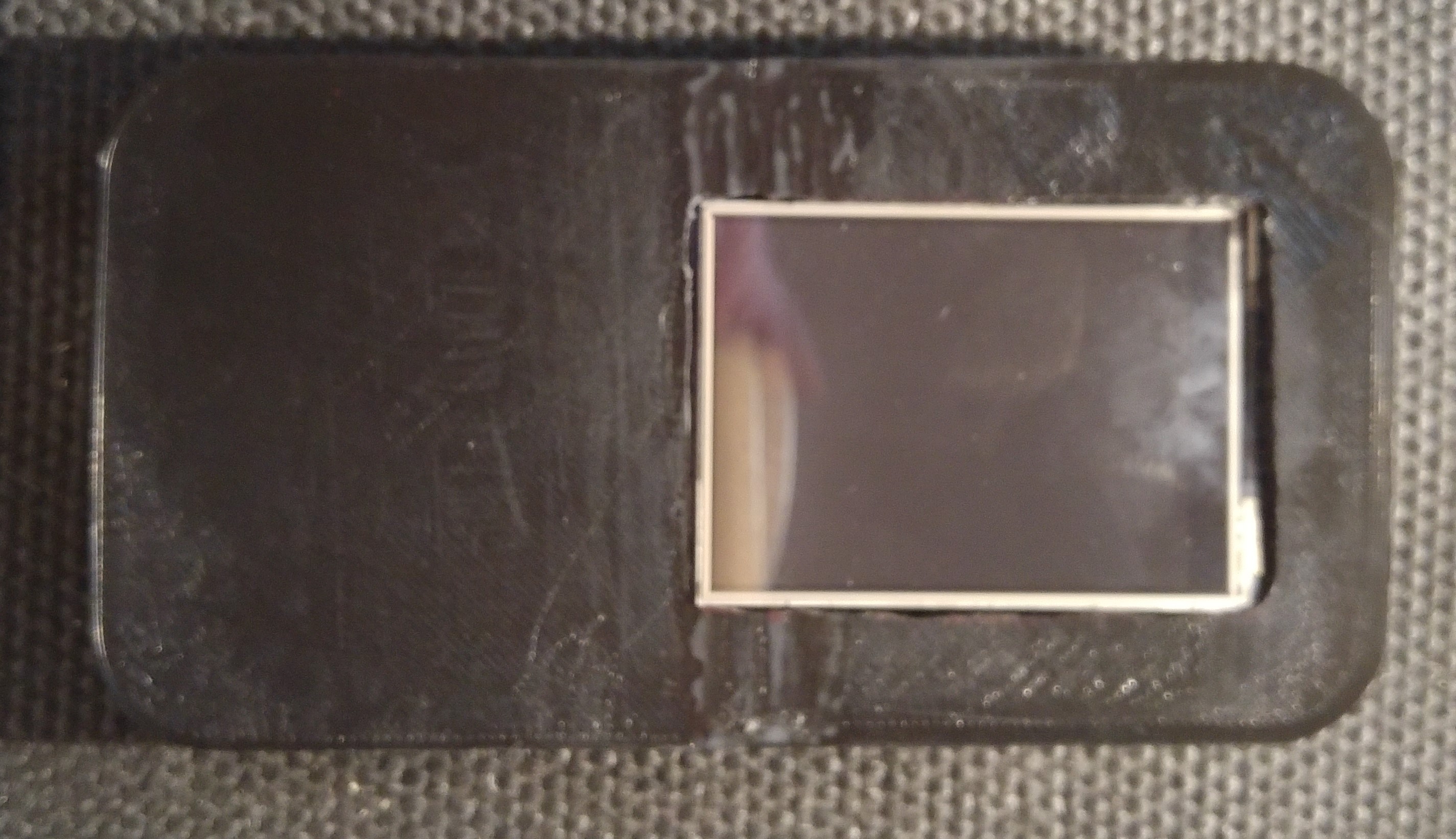
- Step 11: Secure the screen to the front Cover. (Current design needs updated to better mount the screen so I used super glue for now)
![]()
![]()
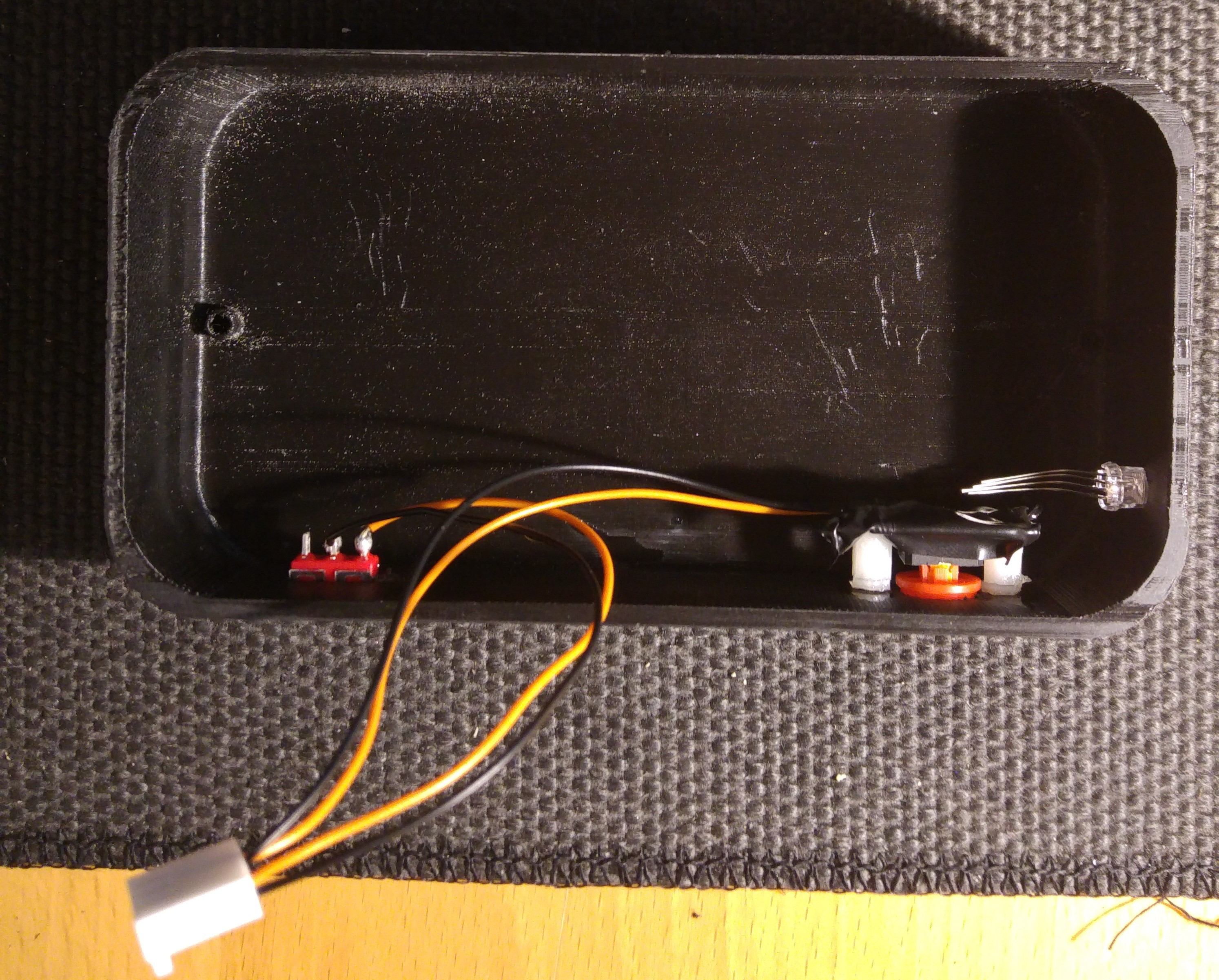
- Step 12: Mount and wire-up the buttons
![]()
![]()
- Step 13: Cover the bottom of the veroboard - I did this to provide some protection from grounding/shorting any of the elements inside the box
![]()
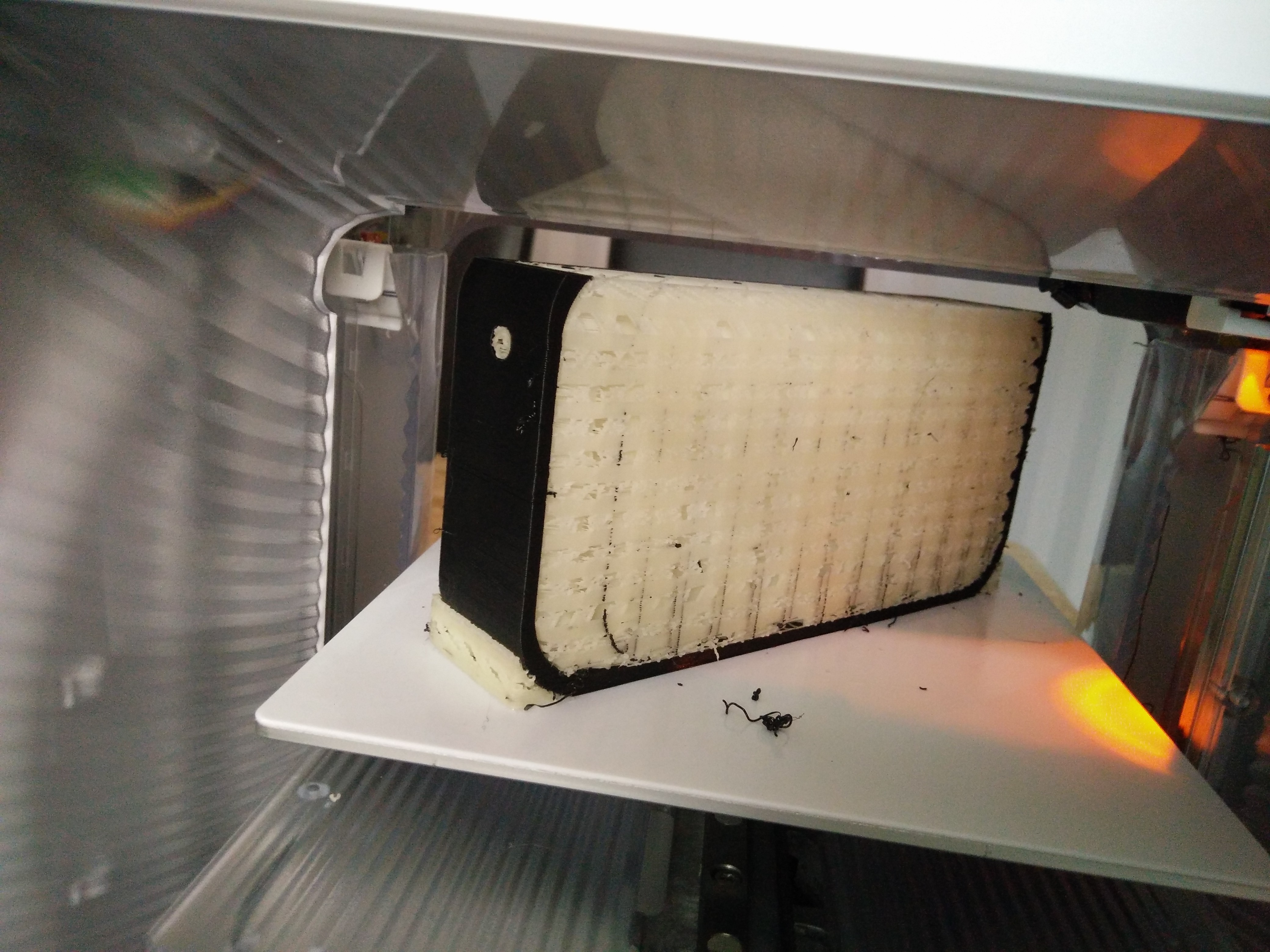
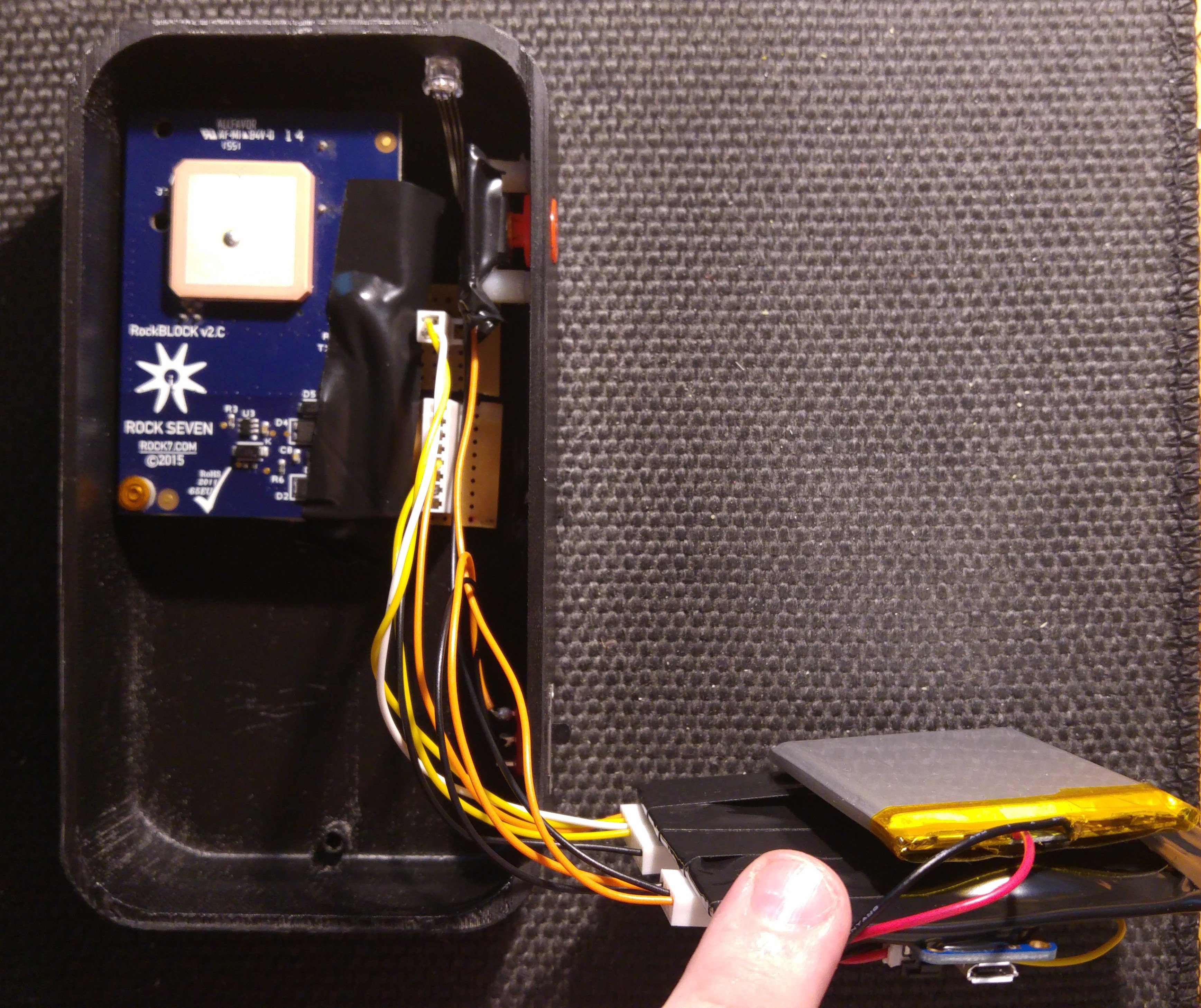
- Step 14: Assembly 1 - Place the rockblock inside the box in the top section. I used double sided tape to secure it down
![]()
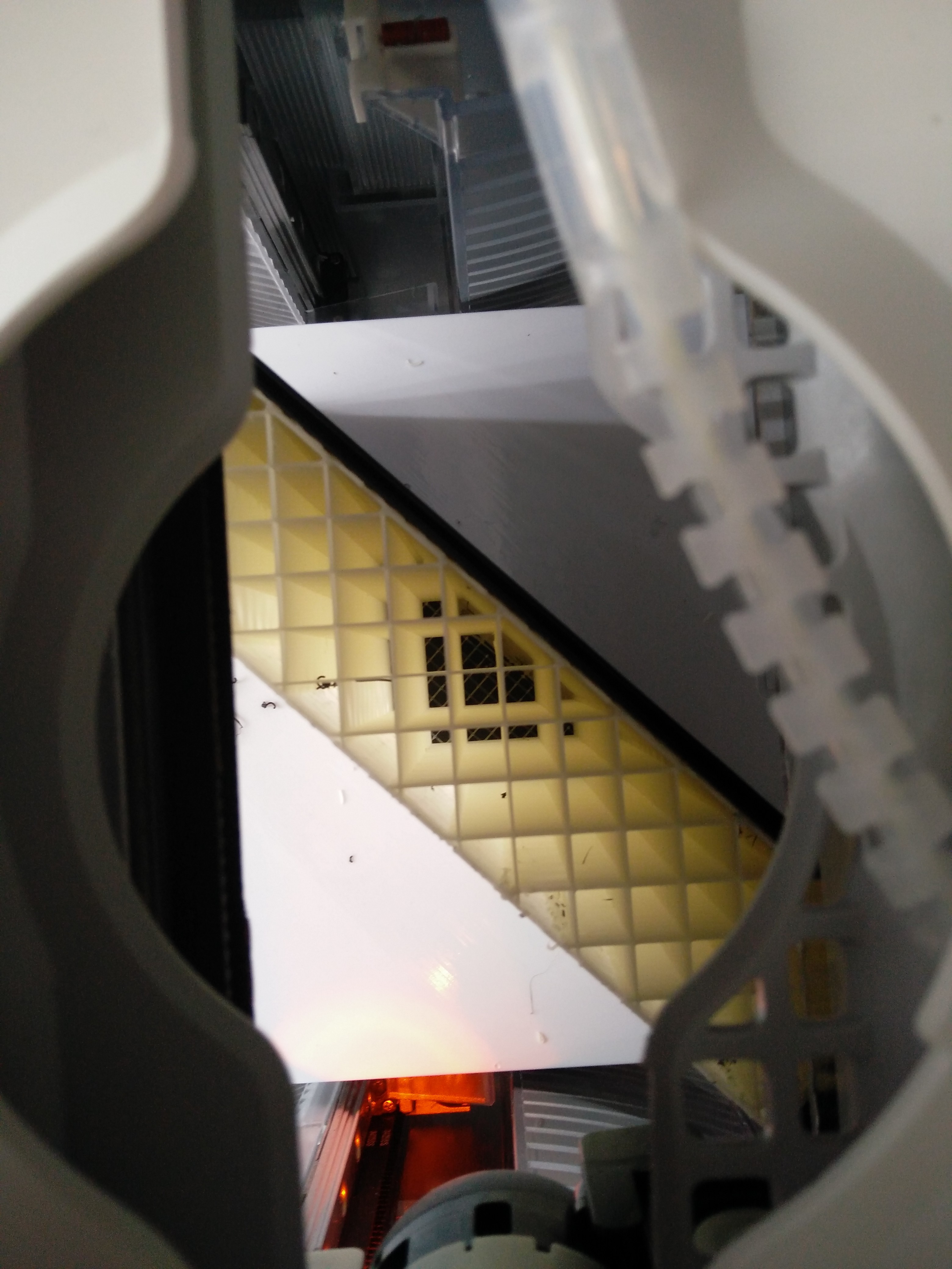
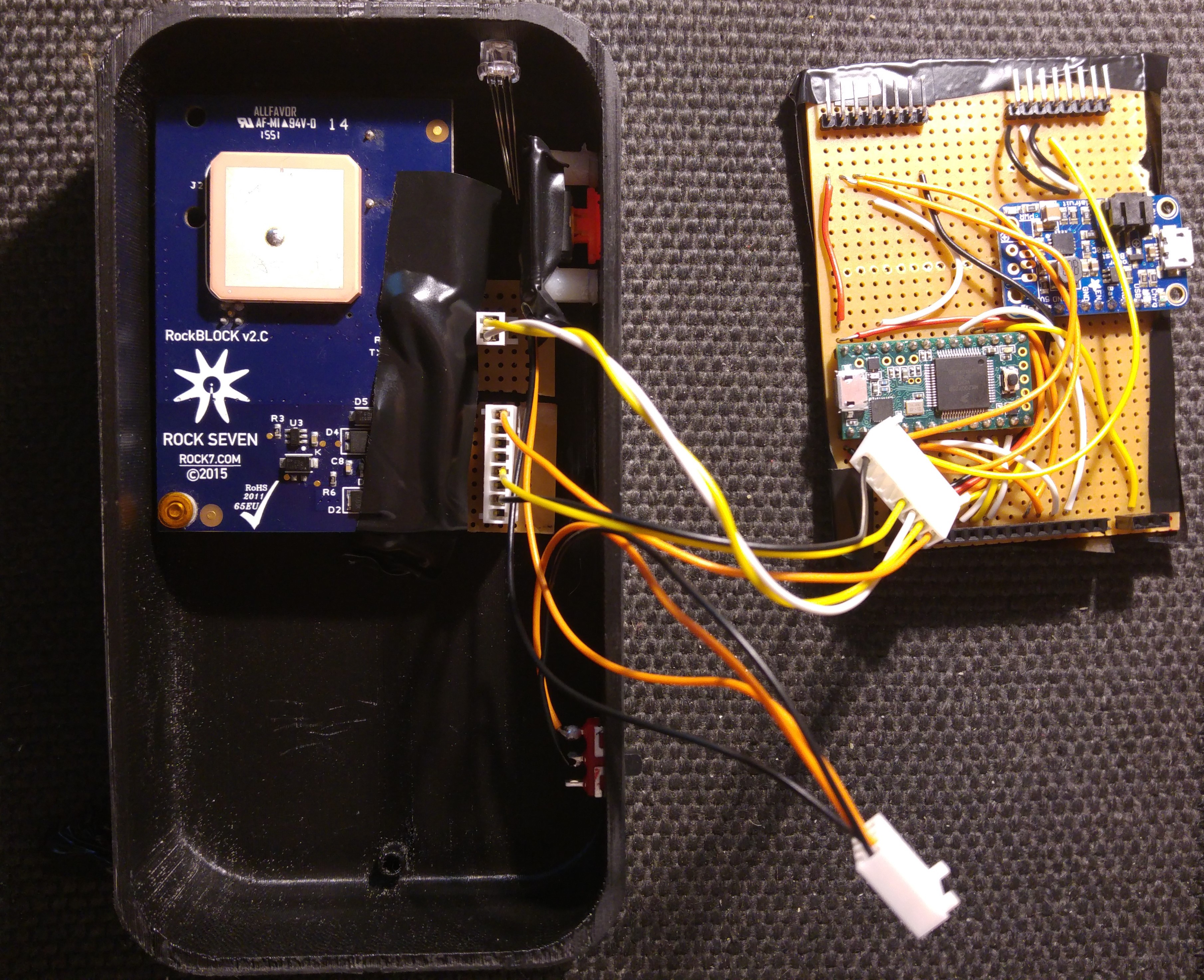
- Step 15: Assembly 2 - Secure all wiring and I attached the battery with double sided tape to the main veroboard
![]()
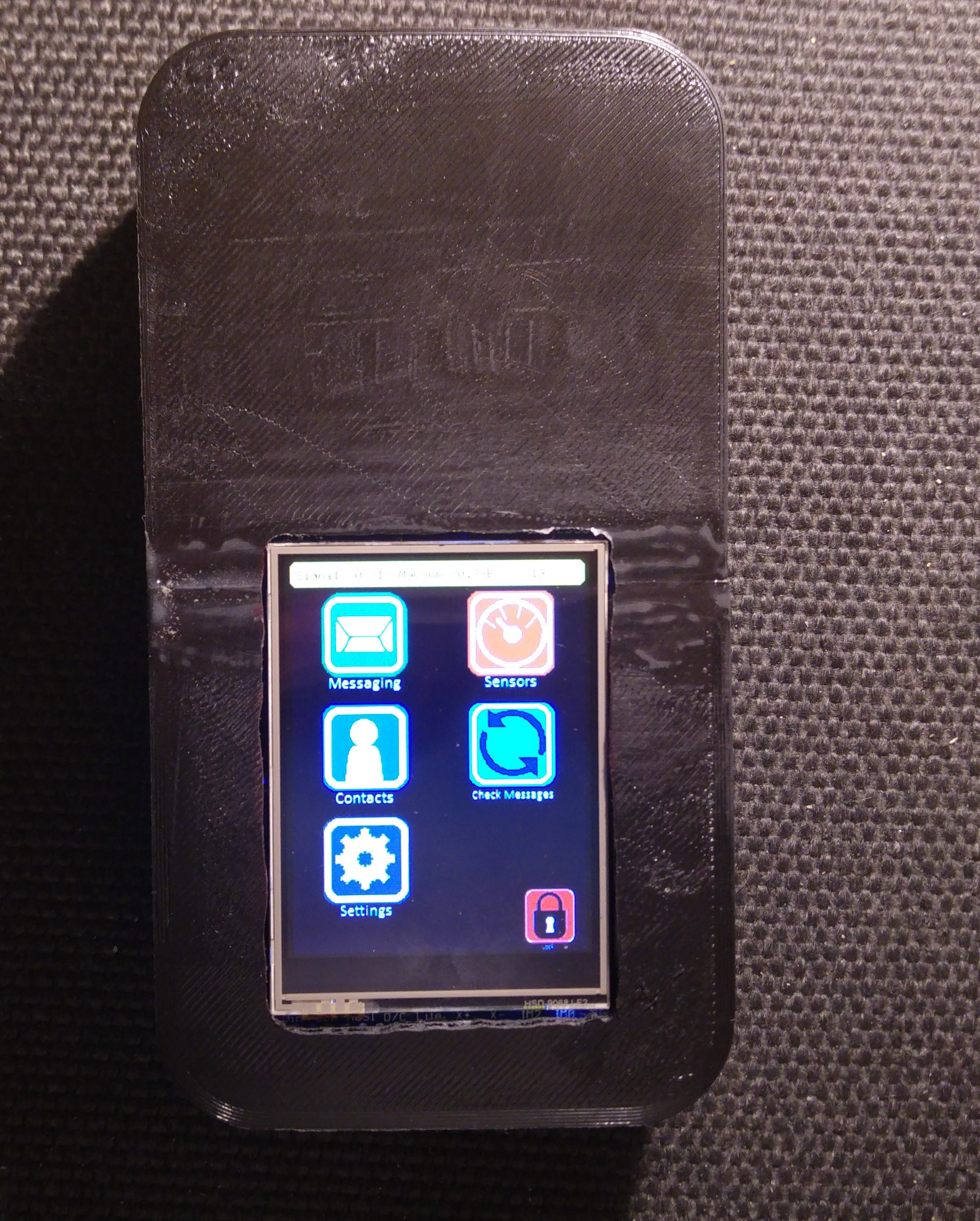
- Step 16: Test your MyComm!
![]()
Thanks for following these instructions! Again, as you can see, this is our first attempt at assembling the first full prototype of the MyComm. There's some design changes to be made to make things easier and more practical. If you have any questions please let us know! You can see a video of the MyComm turning on for the first time below:
JW -
Build Instructions (1) - Software Preperation
09/23/2016 at 09:36 • 1 commentTo keep the instructions page clean I'm creating individual logs for the Prototype build and linking it in the instructions page. This log describes the software preparations you need to take to be able to program the MyComm.
Code Preperation:
In order to program the Teensy you'll require a compatible version of the Arduino IDE (Arduino.cc version) and the latest version of Teensyduino from here: https://www.pjrc.com/teensy/td_download.html . (As of writing Teensyduino V1.3 is compatible with Arduino V1.6.11)
MyComm code repository is here: https://bitbucket.org/JWScotsat/mycomm-scotsat-dev
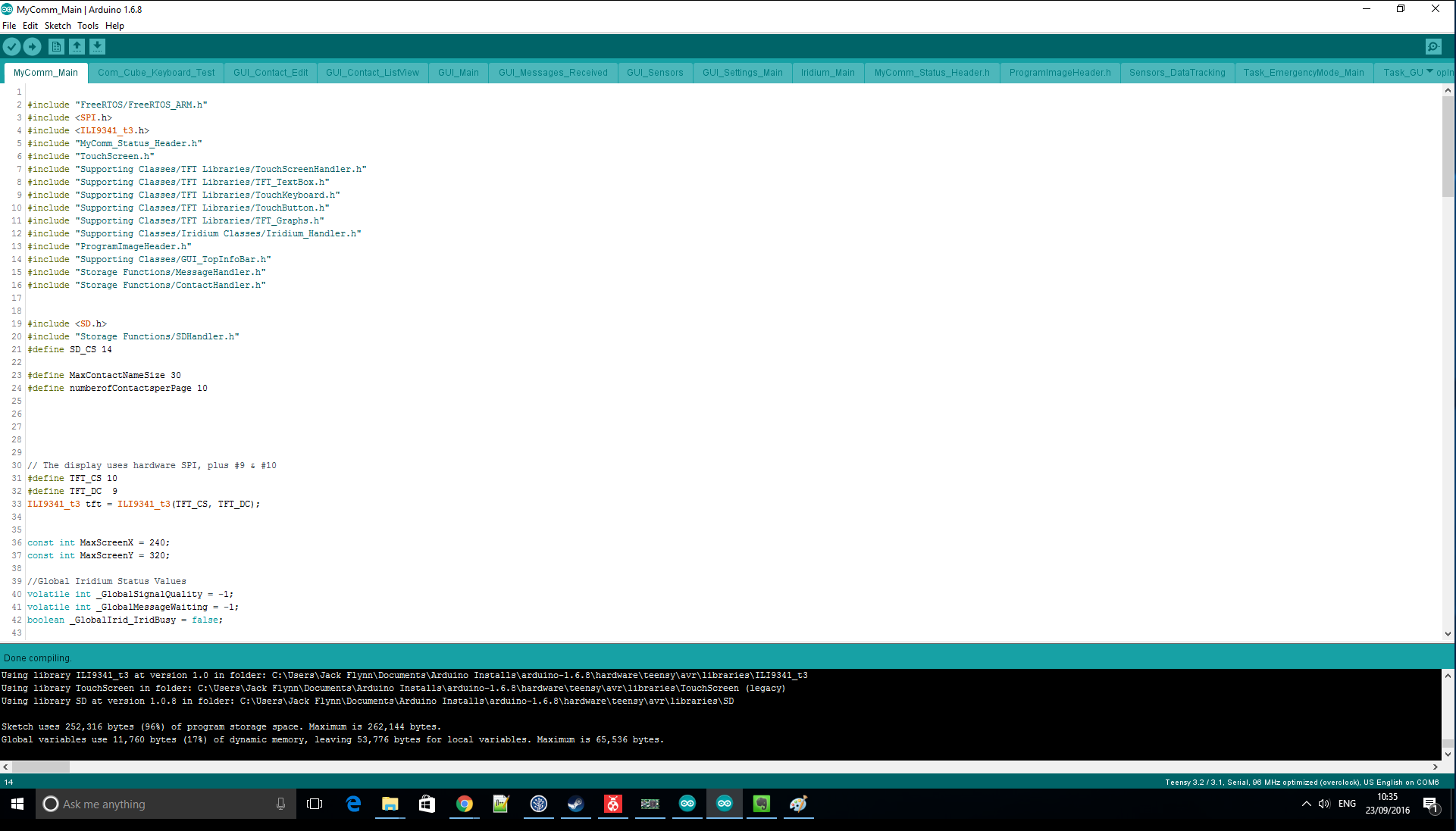
Clone or download the repository using your standard git package or through your browser. The folder contains all of the library files required so open the main file "MyComm_Main.ino" in the Arduino IDE. Do a "Verify" check to make sure everything is working before continuing.
If everything is installed correctly you should see the following bellow:
![]()
Code Test:
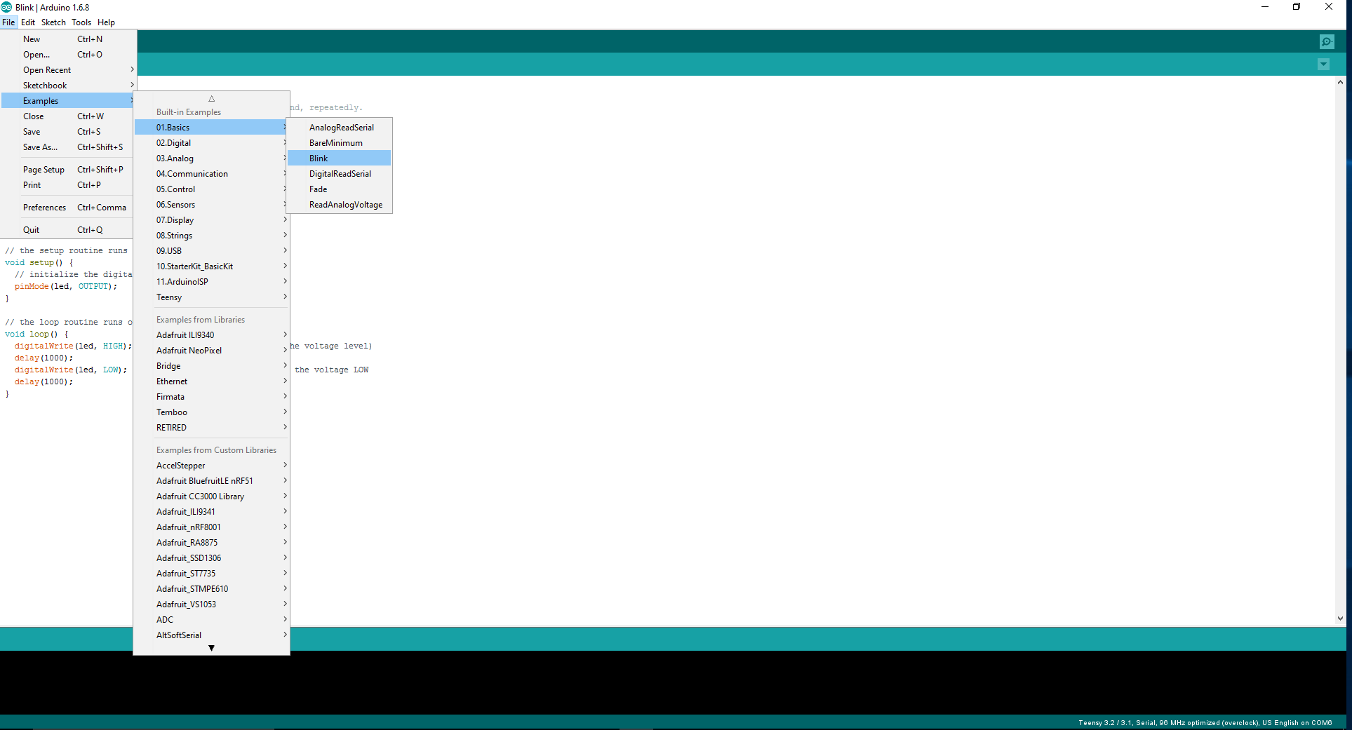
To make sure your IDE is setup correctly open the standard "blink.ino" file in arduino.
![]()
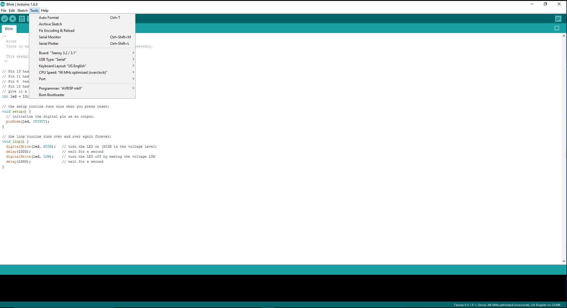
Select the options from the drop down menu in Arduino for Teensy 3.1/3.2. Set "USB Type" to "Serial" and set the "CPU Speed" to "96MHz optimised".
![]()
Upload this code to your Teensy and you should see the LED on pin 13 blinking!*
Keep the blinking code on the Teensy as it'll come in handy when we move to the hardware build.
JW
*If you haven't reprogrammed the Teensy since buying it (so it's completely fresh) you may need to press the hardware button on the Teensy before windows recognises it. Press the button on the Teensy and press "upload" on the Arduino IDE you should hear windows "beeping" to show USB connections are happening. Any issues please see the Teensy forum for further help.
-
Rocking with the RockBlock (the Iridium modem)
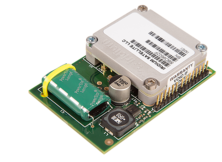
09/21/2016 at 09:06 • 0 commentsAt the heart of our prototype MyComm is a RockBlock which handles the Iridium communication. The RockBlock is made by Rock Seven, an Iridium value added reseller. Their aim is to make satellite communications accessible to everybody in a simple and easy to understand way and they manufacture a range of Iridium-based satellite tracking & communication systems and airtime contracts.
![]()
The RockBlock is basically a break out board for the Iridium 9602 modem, providing it with an antenna and its power supply requirements. It exposes the modem’s serial interface via a breakout connector over serial, or USB. The Rock Seven management system can be used for managing your devices and configuring API access. There is also an Arduino library - IridiumSBD by Mikal Hart, that has made development quick and relatively painless.
A RockBlock can be purchased from Rock Sevens store and currently costs £159. Line rental is paid in blocks of one month at £8 per month. You only pay for months in which you wish to use the RockBlock and no annual contract is required. Credits are used each time you transmit. One credit is used per 50 bytes (or part thereof) of message sent or received. One credit is also used if you check your mailbox and there are no messages waiting (A mailbox check). Credits do not expire, even if you are paying no line rental. Costs for credits depend on what bundle you buy ranging from £6.00 for a 50 credit bundle to £800 for 20000.
We’ve uploaded the RockBlock data sheet and other useful documents to the files list above. All in all we’ve found that working with the RockBlock is really fun and easy. It opens up a whole range of interesting applications and we look forward to seeing what other people do with it!
JG
-
Sat Test(2) - We Just Got A Message!
09/20/2016 at 13:42 • 0 commentsAfter putting our server online we were lucky enough to get a user signed up and they sent us a message to the MyComm. This was a great oppertunity to show the MyComm pulling down messages and saving them so I thought I'd put up a quick video to show our progress with the Rockblock modem. Thanks again to aamarsh for the message!
JW -
Documentation Update(1)
09/19/2016 at 13:14 • 0 commentsBuilding things is fun! Writing it all down sometimes takes a back seat when you're on a creative roll. Today I've been putting together documentation to try and flesh out our Hackaday project page. Here's a list of what I've added:- 3d CAD Files (STL 3d print compatible)
- 3d CAD Files Zip - V0.1 Mock up files for Prototype and Final Design - AutoDesk Inventor
- Fritzing Schematic & Breadboard PDFs for viewing
- Fritzing File - (uses the adafruit frizing part library from here)
- Wiring List - Text file with a pin -> pin list for wiring
-
Serving up some code!
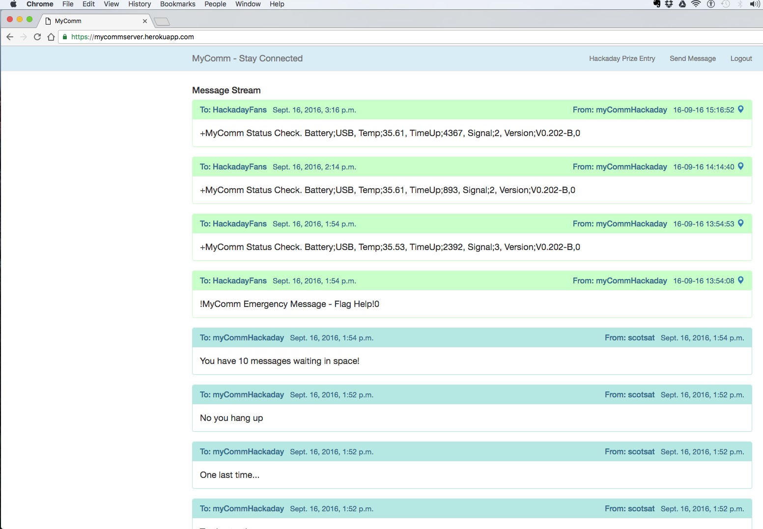
09/16/2016 at 15:22 • 0 commentsI’ve now got the prototype server running in a way I’m pretty happy with so thought this would be a good time to share some info about how it’s set-up, where you can find the code and what it’s doing.
![]()
The application itself is built using Django - "a high-level Python Web framework that encourages rapid development and clean, pragmatic design.” I chose it because I wanted to use Python - it’s popular, robust, flexible and also easy to use and learn - I like using it. Also I find Django pretty intuitive, it has good documentation and seems very well supported on things like stackoverflow.com. Overall I’m happy with the choices.
All the code is stored in a GitHub repository: https://github.com/johngrantuk/myCommServer it’s (fairly well?) commented and should be relatively self-explanatory. Anyone should be able to just download the code from there if they wanted to set-up their own server.
Our prototype app is currently hosted by Heroku which is a cloud application platform that handles hosting, deployment, etc. The app is currently running on one of the free dynos, which is basically a Linux container. And yeah that’s free as in free! One reason I like Heroku is because of how easy they make it to deploy an app. I connected the dyno to my GitHub repository then whenever I want to deploy updated code I just hit the Deploy Branch button, it’s very cool.
The app itself has three main tasks:
- Display a page showing messages sent between the server and our MyComm prototype.
- Handle API requests to/from the Iridium service - for sending and receiving messages over satellite.
- Allow users to register and login to send a message to our MyComm prototype - we thought this could be fun for people to try as well as helping us to test the functionality
You should be able to see how these tasks are handled by looking at the functions in the views.py file. Hopefully this code makes sense to anyone trying to set-up their own version but if there are questions just post in the comments.
So that should give everyone an overview of how things are set-up. Now with some trepidation we invite you to visit the site at: https://mycommserver.herokuapp.com/ and feel free to register and send us some test messages!
JG
-
Sat Test(1) - Sending Message Out
09/13/2016 at 14:10 • 0 commentsA lot of work has gone into the programming side of the MyComm recently. If you happen to check out our BitBucket repo you'll see a good number of commits over the past few days. A major part of this programming has been spent on interfacing with the Rockblock Iridium Modem. We now have the ability to send messages out! John's been working on the web-end of things too so we have a very basic page up and running that receives the messages sent from the MyComm. Very cool! Check it out in our latest video log -
-
Assistive Technology - How MyComm can help!
09/06/2016 at 09:35 • 0 commentsGlobal communication is great when you want to send a message in a hurry or just to remind family you're safe and sound. However, in a worst case scenario, global communication could potentially be vital. An idea we've had from the start is to have an "Emergency" button on the MyComm. The plan is to get a "pre-canned" message to a number of contacts to tell them you're in trouble and you need help. Joining this with GPS data also allows for your emergency contacts to know exactly where you are in the world. When first setting up the MyComm you'll be asked to setup this emergency functionality so that you can create a pre-recorded message that will go out to a number of contacts that you define. Initially the idea is that this setup will be done on web-end of the MyComm service. There are a number of reasons we've considered this:
Ease of data input - Writing a long message and defining multiple contacts can be cumbersome on the latest smartphones, by going through a pc web service it will make things easy and quick. It will also allow easy access to edit contacts or messages when the user requires.
Reliability of data - By entering directly to the web service it means the MyComm doesn't have to sync the message or contacts to the webserver; Saving on cost and ensuring the functionality is setup correctly.
Reduction in emergency data - By having the web services handle the emergency message and contacts it means that the MyComm only has to send gps position and an encoded flag to say that the message is an emergency. There's no need to send multiple messages over the satellite network; One message as simple as possible helps ensure the message gets out without worries of data loss or multiple messages not sending.
Test Service - An option we could have during setup is to send your emergency contacts a message to say "Hey, you've been chosen by --User-- as an emergency contact for their MyComm messaging device. If you receive a message from our service please be aware that --User-- may require your help. We'll include their GPS position as well as a customised message that they have setup. Thank you for being a trusted contact!" - By going through the webserver directly the cost of satellite data can be removed from this test message.
Setup Trusted Users - This will be discussed further down, however, an additional idea for emergency use is to have the MyComm reply to queries from trusted users. This will allow someone to query where the MyComm is and receive GPS data and status.
So how will it work?
The key factors of the emergency use are to be simple and reliable. By having a hardware button on the device this allows for use without the touch screen; reducing the power consumption and avoiding any issues if the touch screen is cracked or non-functional. Further consideration means that we'll need a 2 step verification for emergency usage; we don't want a message going out because the button is pressed in a bag or pocket. One way to ensure this is to have the power switch with multiple positions; Off, On, Low Power, and Emergency. Placing the power button into emergency and holding the emergency button for 4 seconds allows the MyComm to be sure an emergency message is intended. Once placed into emergency mode the MyComm will continually attempt to send the message out. The RGB LED on the top will flash to show the message is trying to send. Once sent, a message will appear on the screen (depending on battery level) and the LED will change colour/flash pattern. The MyComm will go into a low power mode and display any reply messages. The message could be sent out again by activating the emergency button again.
![]() --MyComm Emergency Button Render--
--MyComm Emergency Button Render--Trusted Users
We're still working on the details of the trusted user idea but the main plan is to give trusted users the ability to ping the MyComm device with a message requesting the current location and status of the device. This would be particularly useful in a scenario where someone is vulnerable to getting lost or are travelling to remote locations and the MyComm can be used to find them. The smaller designed MyComm device that doesn't have a screen would be useful for keeping on someone without being bulky or requiring user input. Once pinged with a special message, the MyComm will reply with the current GPS location, as well as battery level and other details, which will be displayed on the web-server that only the trusted user can access.
-
Enclosure Design (2) - 3d Print in our Hands!
08/23/2016 at 14:39 • 0 commentsThings have been a little slow on the MyComm front. We've had other projects taking our time. However, after winning 2 of the Hackaday monthly categories we've been able to use some of the funds to get some 3d prints! Video below shows what they look like:
I was able to get the screen easily fitted to the "Consumer Mock-Up" - This case is the one we're hoping to produce for actual users. It'll likely make some design iterations depending on how custom PCB designs go and component selection. However, there's nothing quite like holding a project in your hands! The 3d prints came out well. They were done by a contact that has his own Cube 3 printer. He was kind enough to send some pics through of the build in progress.---------- more ----------
![]()
--3d CAD Designs --
![]()
![]()
![]()
-
Automation Entry - Automatic location & remote data tracking
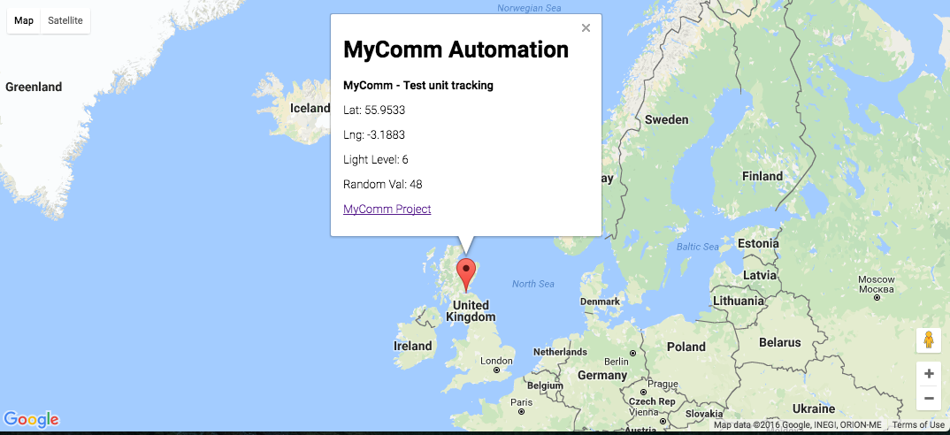
08/21/2016 at 17:03 • 2 commentsWhen the Iridium service delivers a message an HTTP POST request to the MyComm server URL. As well as the message data other parameters such as device serial number and imei number are included. Also included is the approximate latitude and longitude of the device at the time it transmitted.
Request Body: {
     "imei":"300234062910580”,"
     device_type":"ROCKBLOCK”,
     "serial":"8532”,
     "momsn":"13”,
     "transmit_time”:"20-08 11:00:47”,
     "iridium_latitude":"55.9533”,
     "iridium_longitude":"-3.1883”,
     "iridium_cep":"3”,
     "data”:”{Light Level: 6, Random Val: 48}”
}
Example POST data
This location data could be used to automatically track location of a remote sensor unit along with the sensor data, the MyComm device can be programmed to automatically send the sensor data say every hour or every day. We’ve used the POST data/location along with the Google Maps API to show a nice reporting page on the MyComm server:
![]()
MyComm
A portable, solar powered, handheld device that provides truly global messaging when you have no alternative.


 --MyComm Emergency Button Render--