Jara
Jara-
Bluetooth Power Modes
09/29/2014 at 18:41 • 0 commentsIn previous post we discussed CPU power consumption in PIP-Watch. Today we look into Bluetooth power consumption because it is significant as much as the CPU power.
Bluetooth Radio States
Practically the only significant part that consumes a lot of power in Bluetooth modems is their radio transceiver. If the radio is switched off the module draws only small quiescent current (less than 2mA in BTM431). Radio is activated by modem to perform one of the following three actions:
- to do a page scan,
- to do an inquiry scan,
- to transfer data to a connected device.

-
Processor Low-power Optimizations in PIP-Watch
09/28/2014 at 13:22 • 0 commentsThe PIP-Watch is a battery-powered device that will be continuously on, hence the average power consumption is one of the most important engineering aspects.
In this post I will go through two simple steps of optimizing CPU power – sleep modes and lowering the clock frequency. In a next separate post we will look into Bluetooth module power.
-
PIP-Watch Boards & Assembly
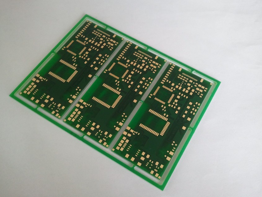
09/17/2014 at 20:57 • 0 commentsThe printed circuit boards for PIP-Watch Zero came from Pragoboard fab on Friday 12 Sept. I ordered three pieces because the cost is practically identical as for two or one.
- PIP-Watch Zero: Pristine PCBs from fab
On Saturday I assembled one board, and on Sunday I tested it and started working on firmware. I had some problems with PLL in the microcontroller - the CPU hard-resetted the instant the PLL was enabled. Eventually I found a bad solder joint on one of the CPU's power supply pins.
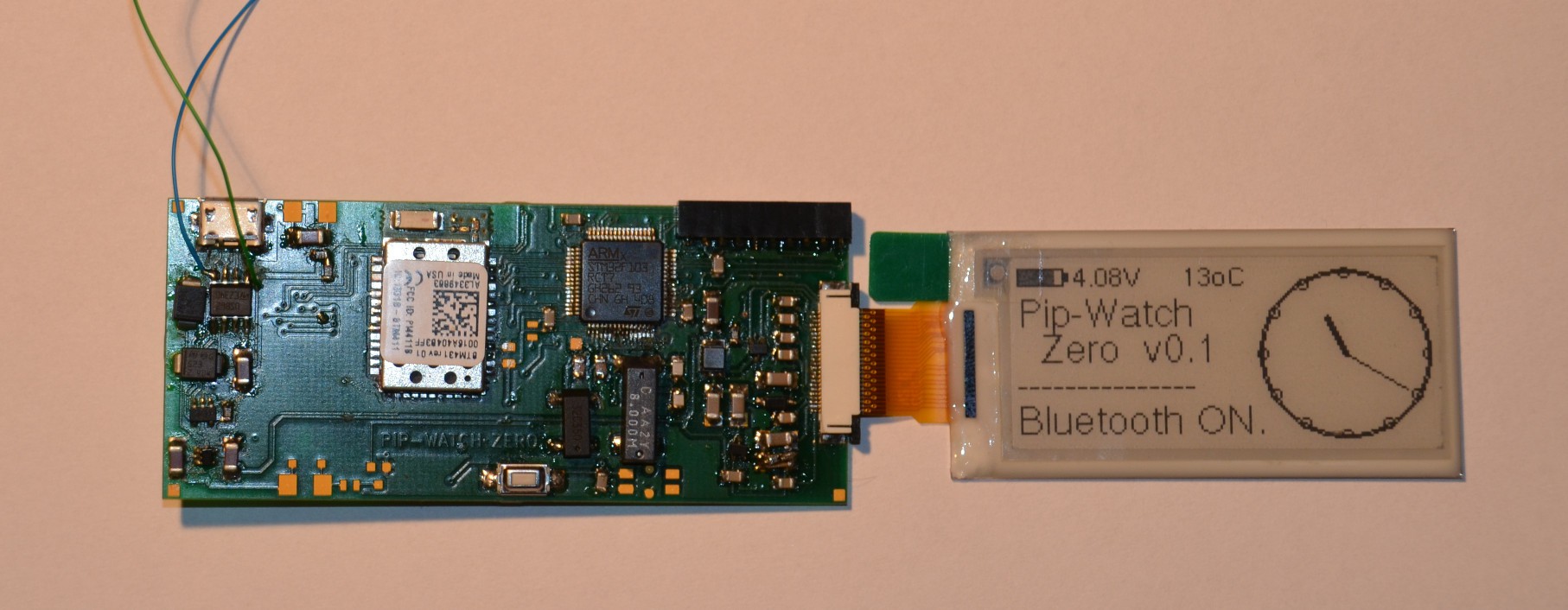
PIP-Watch Zero: Assembled board from the bottom
-
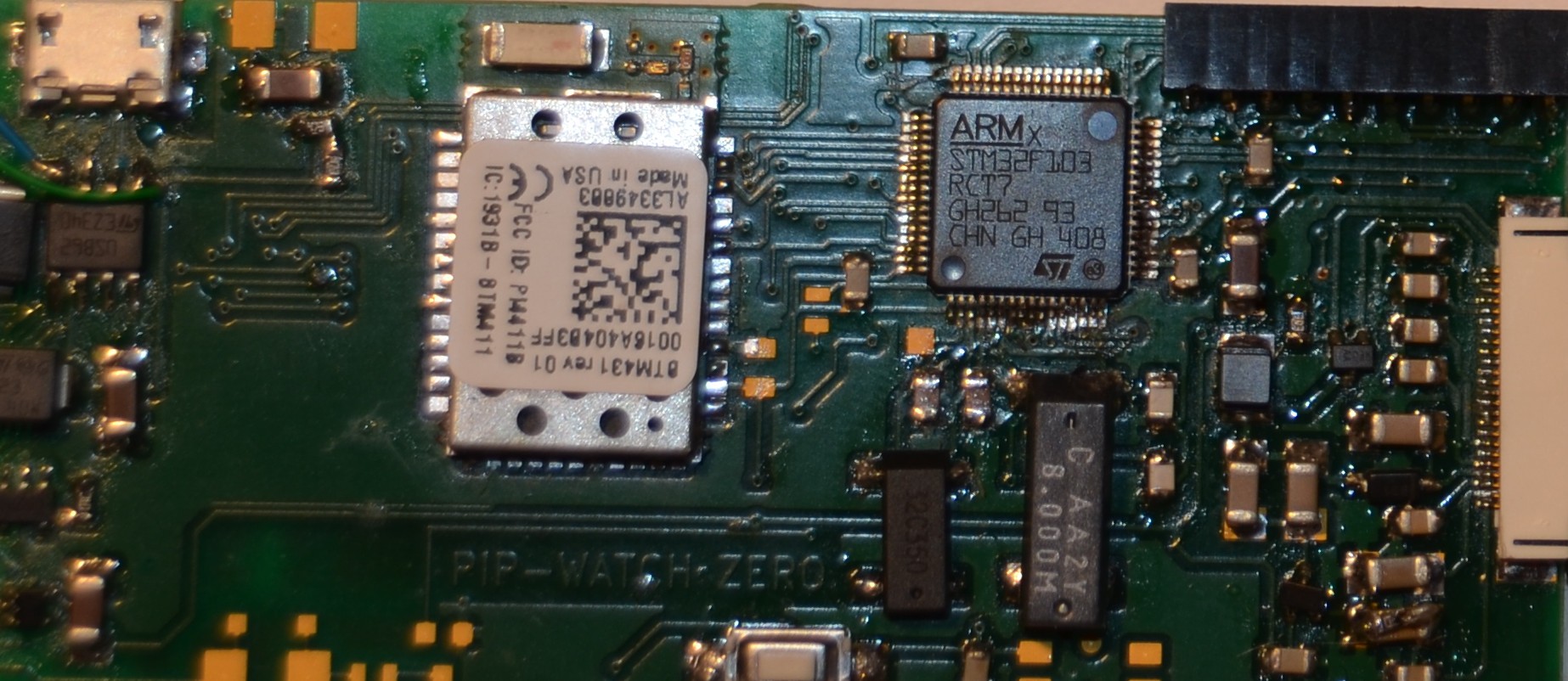
PIP-Watch Zero: Top PCB side, unfolded.
So far I tested the CPU & JTAG, the eInk EPD display, Bluetooth modem access (but not the BT communication itself), and LEDs. I had issues with bad solder joints (both shorts and cold joints) because the PCB footprint for the CPU (the LQFP64 package) was apparently designed for the reflow process, and it is not suitable for hand soldering. Silly KiCAD libraries!
-
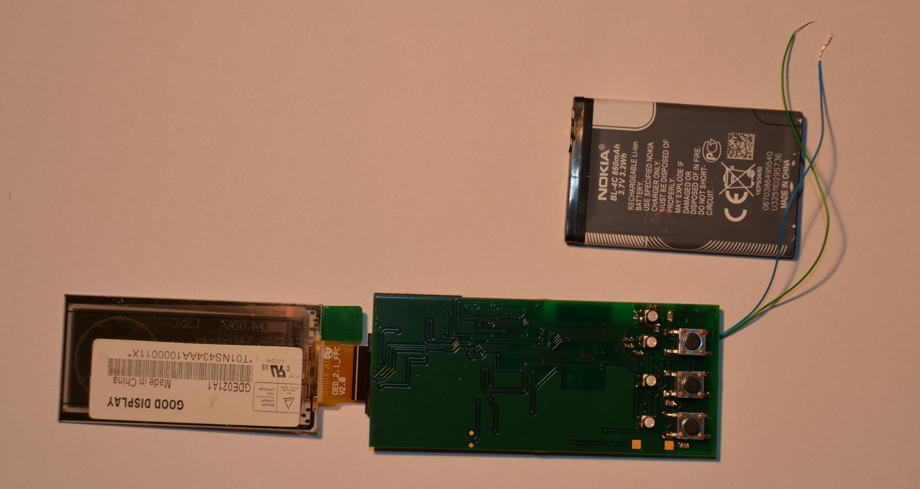
PIP-Watch Zero: Assembly
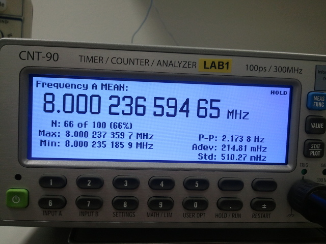
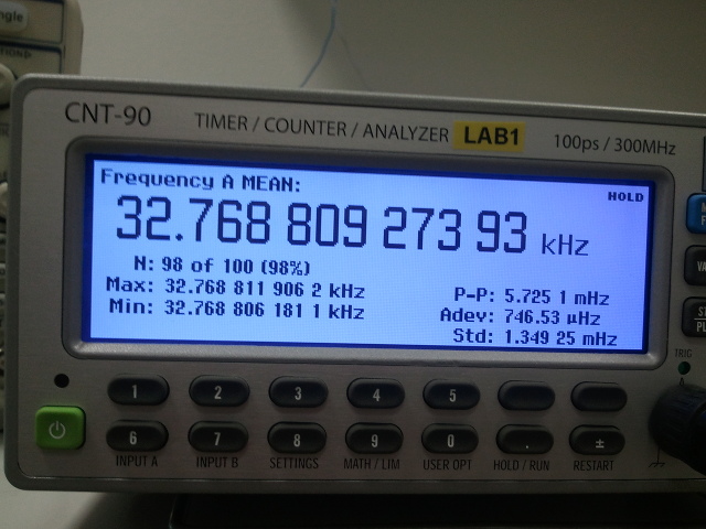
Measuring crystal frequencies:
-
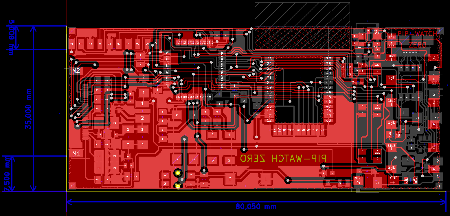
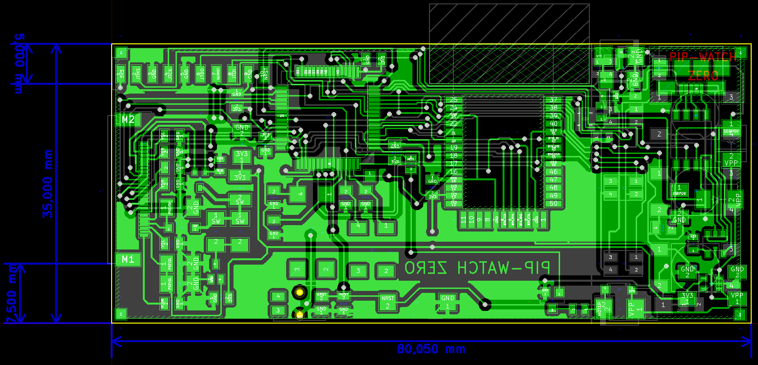
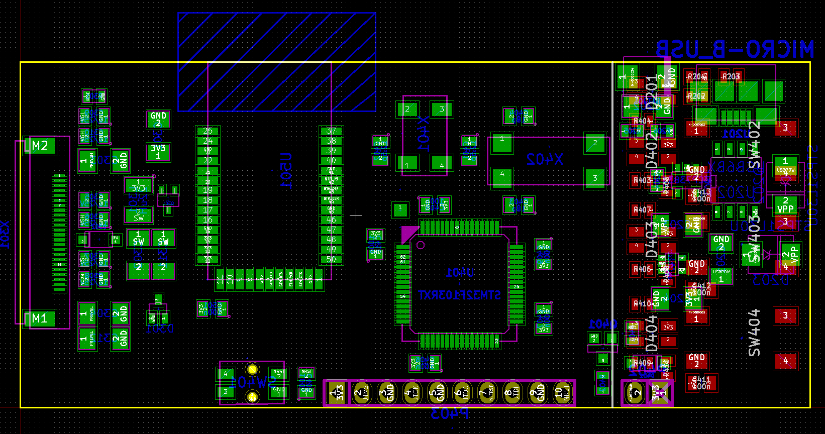
PIP-Watch “Zero” – Schematic, BOM, and Layout
09/07/2014 at 18:39 • 0 commentsSchematic [PDF], BOM, and PCB layout for my PIP-Watch “Zero” was completed during this week. Layout data was sent to a local PCB fab – pragoboard.cz. The board should be ready and shipped during the next week.
The PCB is is 80mm*35mm. The top side is dedicated to the EPD display, battery (underneath the display), 3 push-buttons and 4 LEDs. The bottom side carries all the main electronics – processor, bluetooth modem, display driver, and power source.
All design files are in the project repository.
Layout Top side:
Layout bottom side:
-
Schematic & BOM
08/24/2014 at 20:28 • 0 commentsI finished a schematic of PIP-Watch Zero, the schematic PDF is on github. I also prepared BOM, which is a basis for a footprint library, and started the PCB layout. The board will be about 80x35mm. The top side will be almost empty, it will only hold buttons and LEDs. Most of the components will be on the bottom side. Battery will be on the top side just under the display.
-
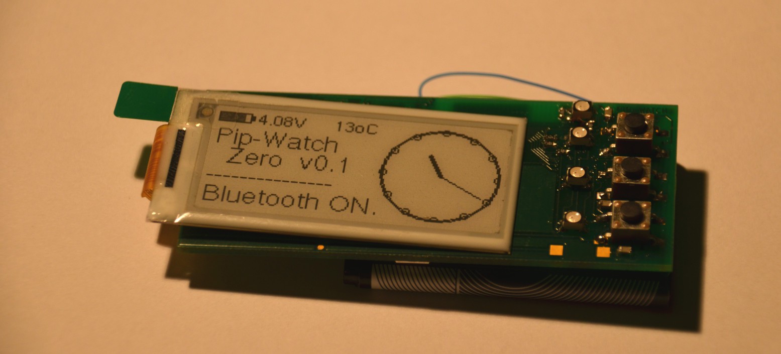
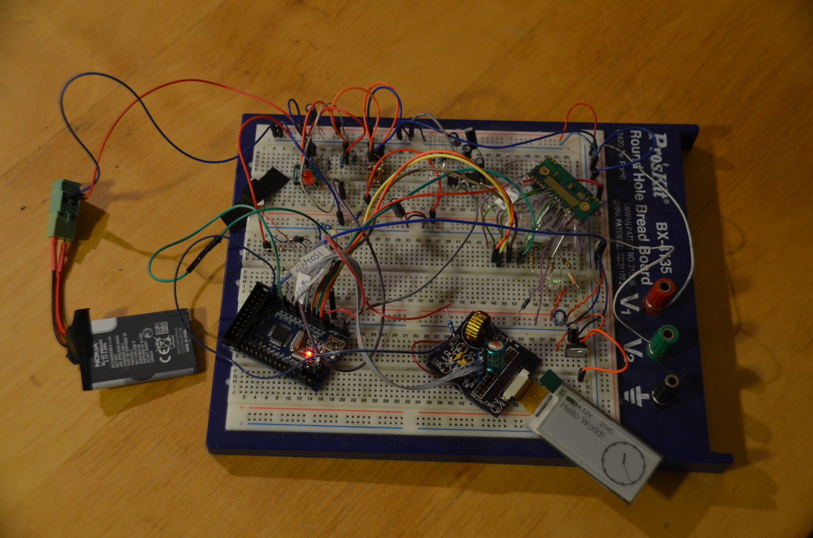
Functional Prototype [Video]
08/13/2014 at 20:32 • 0 commentsVideo: PIP-Watch - A Functional Prototype
Breadboard Photo:
-
FreeRTOS tasks and queues
07/27/2014 at 22:01 • 0 commentsIn my previous homebrew projects I did not use any operating system in the embedded processors. Software was programmed on a bare-metal hardware. In my Talking Clock project I created a simple cooperative event-processing abstraction layer, but it was very limited.
In PIP-Watch there are multiple independent tasks that should execute concurrently and exchange information at specific points. These are: Bluetooth modem task, Display drawing task, and Battery monitoring task.
-
Framebuffer Drawing with u8glib [VIDEO]
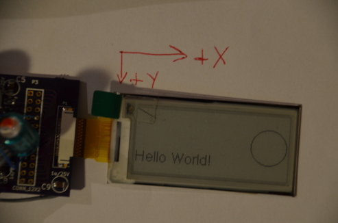
07/02/2014 at 21:36 • 0 commentsGDE021A1 is a graphics display with a resolution 172x72 pixels, each pixel is 2 bits deep (4 shades of grey). The display has an internal controller SSD1606 with a framebuffer. The framebuffer size is 172*72*2/8=3096 Bytes. When the display is powered up, the system processor sends initialization sequence that first sets up controller's internal registers (the controller SSD1606 is fairly generic) and then sends new framebuffer content. The display controller then autonomously pushes the framebuffer contents to the physical screen.
The display controller can be configured to orient the framebuffer almost any way. I configured it into a landscape mode, with the X-axis going right and the Y-axis down, as shown on the photo.
-
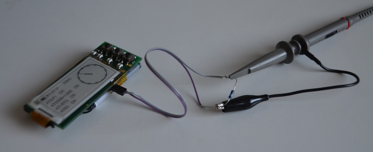
EPD Display Working!
06/18/2014 at 21:37 • 0 commentsToday I have managed to get the GDE021A1 ePaper display (EPD) working! I used my minimal EPD-Driver board, which implements a flat-flex cable connector and a booster circuit for the display. The booster generates high voltages needed for display operation (around +-25V). The display is driven by STM32F101 Cortex-M3 CPU, mounted on a universal PCB. The picture below depicts my workbench setup:
-
Li-On Battery Charging (and Discharging)
06/11/2014 at 20:18 • 0 commentsIn my PIP-Watch project I will use a Li-On battery to provide power. Li-On batteries are easy to use in hobby projects: they are light, small, with high capacity, and they come in variety of sizes. Most (not all) Li-On batteries have nominal voltage 3.7V, hence you can directly power your standard 3.3V digital logic directly, using only a simple low-drop linear regulator (e.g. LD59015).
For my first experiments I chose Nokia BL-4C Li-On battery. It’s nominal voltage is 3.7V, charging (maximal) voltage is 4.2V, the capacity is 860mAh.
PIP-Watch
Pip-Watch (Personal Information Panel) is an open-source smart watch with an ePaper display, a bluetooth modem, and a Li-Ion accumulator.