Close
0%
0%

TritiLED

Multi-year always-on LED replacements for gaseous tritium light sources

Similar projects worth following
TritiLEDs are always-on battery powered LED glow lights for general night-time marking use. Radioactive gaseous tritium light sources (GTLSs) are allowed in the United States in several consumer product categories, including watches, compasses, and gun sights, but general-purpose markers are considered "frivolous" and are prohibited. Leveraging advances in LED efficiency, battery capacity, and microcontroller technology, TritiLEDs run from 1 to 25 years depending on battery choice, and while larger than typical GTLSs, can replace expensive and sometimes illegal tritium lighting in a variety of applications (including the frivolous). Version 3.0 of the design is complete and released under an MIT license.

Concept

This is a project born of frustration. As an amateur astronomer and astrophotographer, I often find myself stumbling around expensive and fragile equipment in the dark. A few years ago, I went looking for glow-in-the-dark markers I could attach to tripod legs and other gear to avoid costly accidents. I quickly dismissed traditional glow-in-the-dark (phosphorescent) materials because of their short half-life and the need to "charge" them before use. Chemiluminescent markers (glow sticks) are better in this regard, but are too expensive to continually replace, and end up in landfills after one night's use. Radioactive markers (especially tritium-based), with their constant glow and multi-year half-life, are technically almost perfect for this application: you can stick them to equipment and you're done. The problem with tritium markers is that they're not legal for manufacture or sale as general-purpose consumer devices in the United States (watches, compasses, and gun sights are exceptions). Even where they are legal, they are still quite expensive. This leaves electronic markers, but these often share similar shortcomings with other glow-in-the-dark technologies: constantly charging or replacing batteries, short-duration illumination, or high long-term cost. What I wanted was a small constantly-glowing LED that I could put somewhere and not have to service for a year or more. Unfortunately, most portable LED lamps are designed as flashlights - they emit a relatively powerful beam for a short duration (hours or days) per battery or charge. There's a race in the industry to make brighter and brighter lights. I wanted to go the other way: relatively dim lights, useful in dark situations, that maximized runtime.

Hazards

Lithium battery powered devices are more dangerous than small tritium light sources, despite the NRC's paternalistic approach and the general public's fear of "radiation." According to the Energizer CR2032 datasheet, an ingested lithium battery can lead to serious injury or death in as little as 2 hours. Further, improperly stored coin cell batteries can short out and cause fires or burst and cause chemical damage. These batteries must be kept out of reach of children and pets at all times, and following Energizer's advice, batteries should be held in compartments with captive screws or other childproof latching devices. While the neat little glowing LEDs may look like a fun thing for a child to play with, children should not be allowed to play with these devices.

Version 3.0

Version 3.0 uses a new architecture with the PIC12LF1571's synchronized 16-bit PWM outputs controling a 74LVC1G123 monostable producing the current pulses.  This allows tuning the peak pulse current to optimize LED efficiency, while separately tuning the overall brightness (and associated battery life).

This version allows the use of three different LEDs, chosen for their unique characteristics.  Each runs for a configurable 1-10 years (or longer) from a CR2032 cell. At minimum brightness, the circuit is estimated to run from 17.6 to 20.2 years on a CR2032.

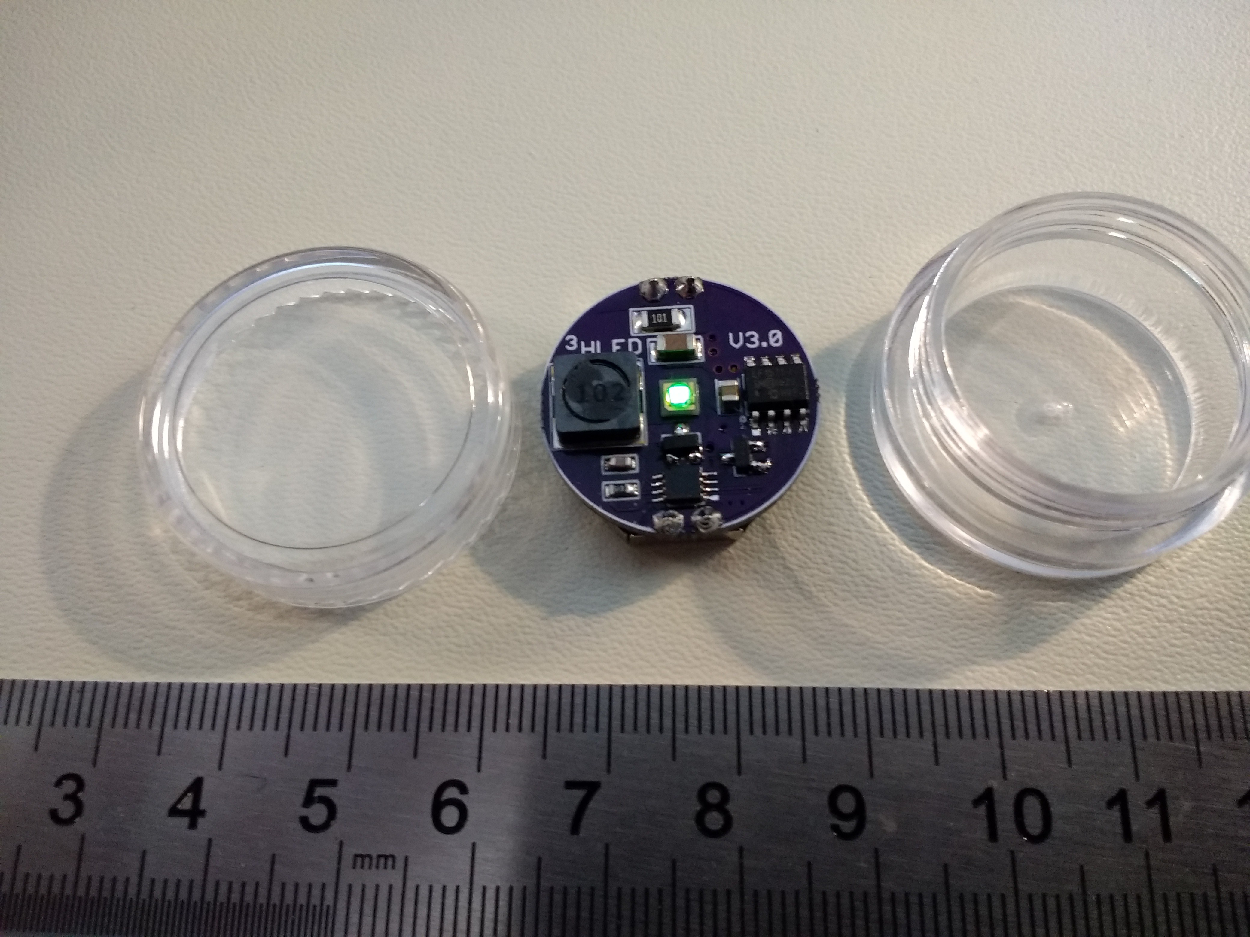
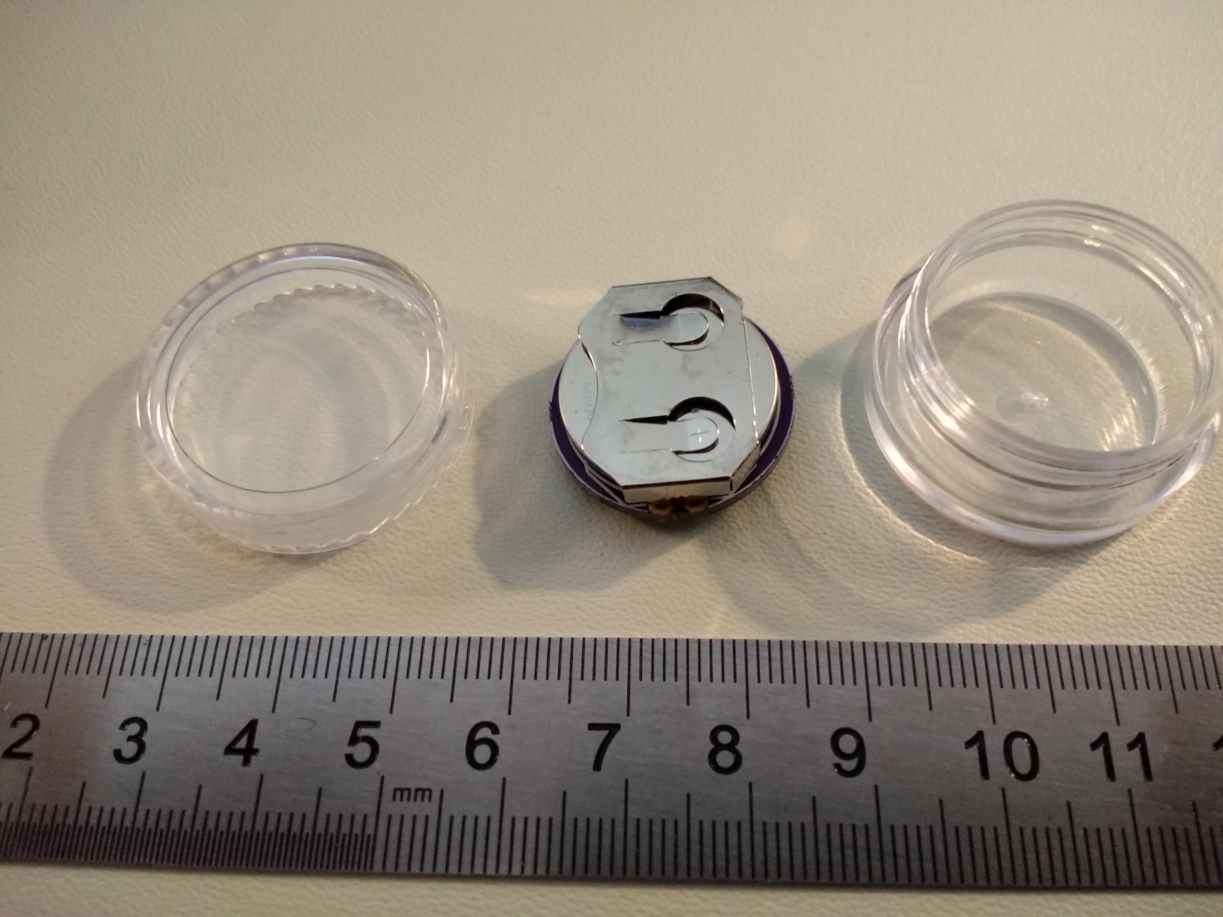
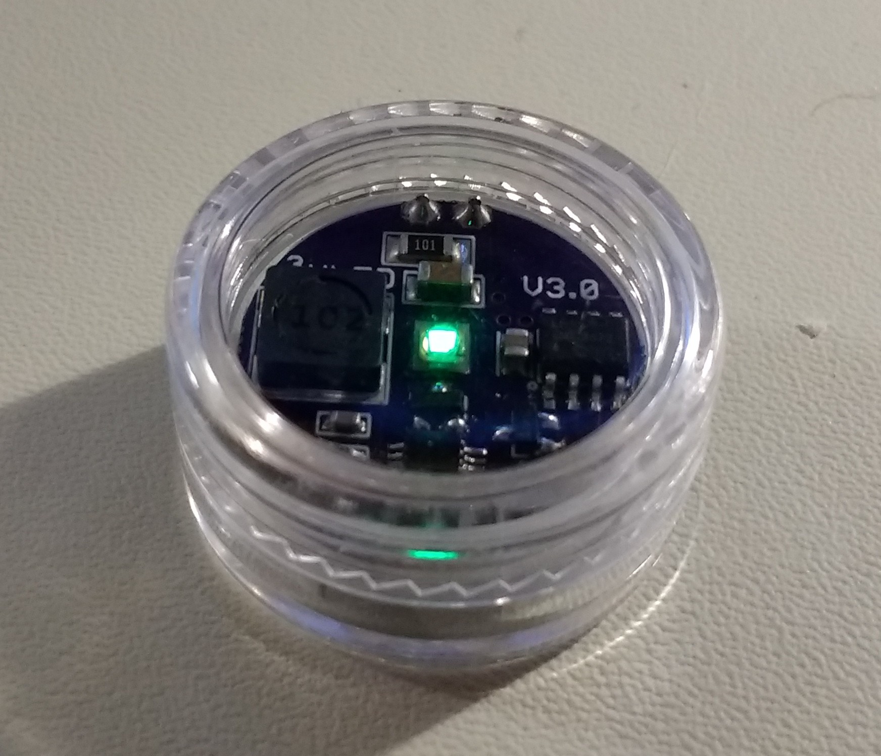
The V3.0 PCB with battery fits inside inexpensive "5g" plastic jars for weatherproofing.  The jars can be permanently sealed with silicone sealant or epoxy if you don't mind breaking a $0.16 jar when you need to replace the battery in a few years.

Details of the 3.0 version can be found in the build log.

Version 2.x

Version 2.x improves on the earlier design by driving the LED at close to maximum efficiency using a simple inductor-based boost circuit. This design also features:

  • Selectable brightness / run-time trade-off (at program time)
  • Bright blinking modes (constant / fast blink / slow blink) with constant runtime
  • Inexpensive LEDs in many colors

Due to the higher electrical and LED drive efficiency, the V2.2 circuit will run for 5 years on a CR2032 (minimum brightness). The brightness can be...

Read more »

make-logo.py

python script to make TritiLED logo (2021)

x-python - 1.70 kB - 02/20/2021 at 14:49

Download

tritiled-logo.svg

TritiLED logo (2021)

svg+xml - 1.33 kB - 02/20/2021 at 14:48

Preview

tritiled.lbr

Eagle library for components used in TritiLED designs

lbr - 26.51 kB - 04/27/2017 at 19:46

Download

20160908_141753.jpg

JPEG Image - 1.28 MB - 09/08/2016 at 18:31

Preview

Li_Battery_Model.tgz

python code for modeling LiMnO2 and LiFeS2 primary cells running low-drain devices

x-compressed-tar - 4.28 kB - 09/03/2016 at 16:32

Download

View all 11 files

  • Dude, where's my MCU?

    Ted Yapo03/11/2018 at 04:39 6 comments

    It seems like overkill to use an MCU just to light an LED, so I've wanted to get a version going just using discretes.  I'm still using a couple of logic ICs in this one, but it's closer.  I don't think it's any better, but maybe simpler and cheaper.

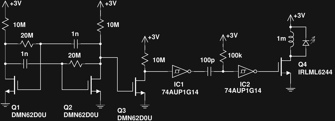
    The circuit is a revised version of an earlier attempt I made using a Schmitt-trigger relaxation oscillator.  The problem with the original version was an enormous power consumption caused by the ST inverter spending so much time in the linear region.  In the new version, I used a MOSFET astable design published by David A. Johnson to drive a one-shot pulse generator I had tried before.  The result looks like this:

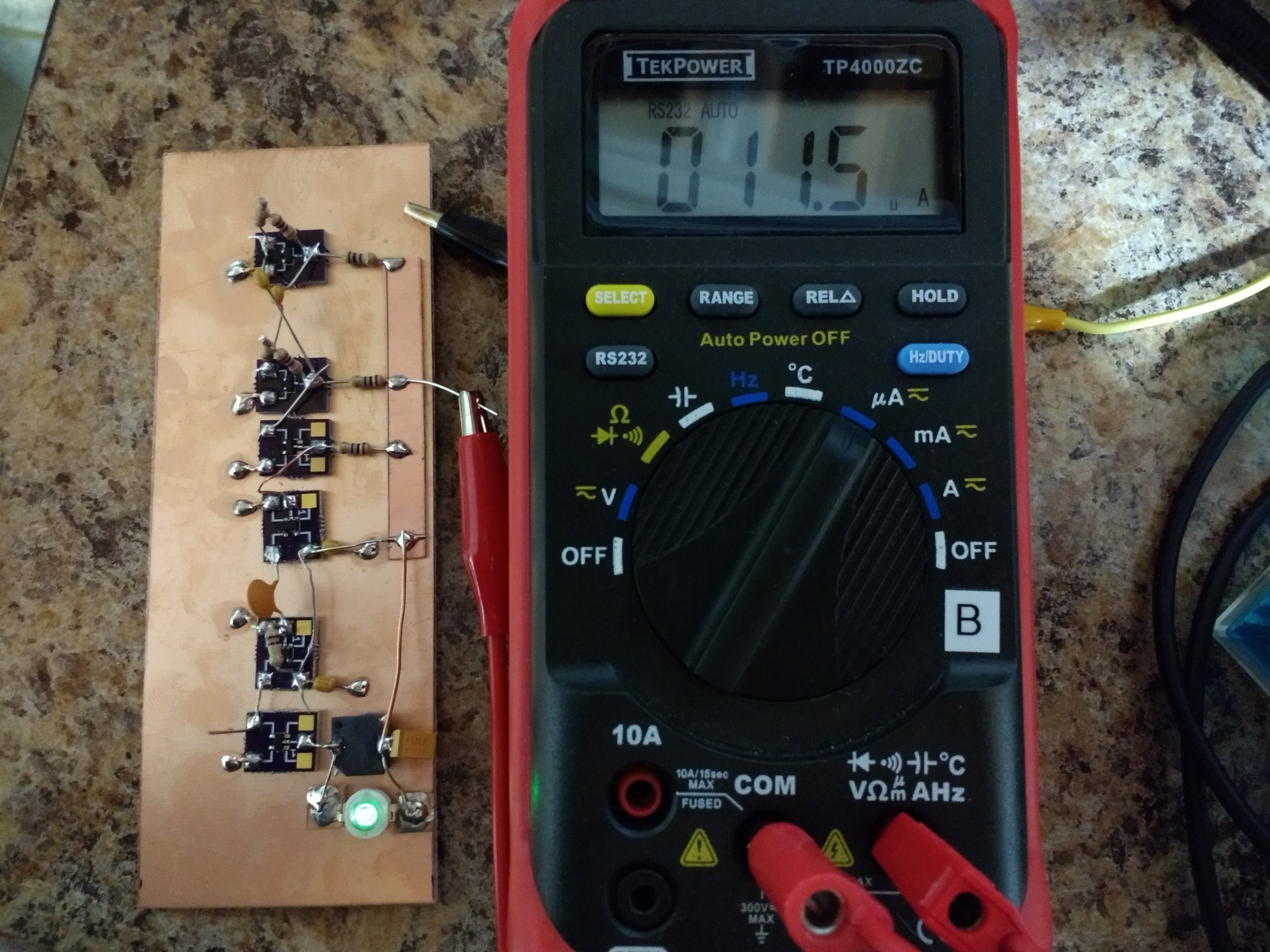
    Q1 and Q2 form an astable multivibrator oscillating at about 35 Hz.  Q3 is used to square up the output and get a rail-to-rail swing to drive IC1, which in turn creates pulses with very fast edges to drive the IC2 one-shot.  The output of IC2 is a pulse of around 12us duration.  This ramps up the current in the inductor to a maximum of around 24 mA, which is an efficient drive level for the LED.

    The whole circuit draws 11.5 uA, which will run for over 2 years on a CR2032 cell.  Without the LED, the circuit consumes around 1.8 uA, so it's at maximum 84% efficient, not counting any losses in the output MOSFET or inductor.  At 35 Hz, it's a little flickery, but increasing the frequency seems to increase the overhead current linearly.  I think most of the the consumption is actually in IC1 whose input isn't driven very quickly by Q3.  For example, I can decrease the current consumption slightly by decreasing the 10M resistor at Q3's drain.  This is counter-intuitive, since a lower valued resistor will draw more current, but what's happening is the faster switching speed with the smaller resistor dissipates less power in IC1.

    I have yet to try other logic families for the inverters.  AUP logic is supposed to be the lowest current, but others might be better with the slow input swings here.  I have some 74LVC gates to try next.  They're also available in 2-gate packages, which would save a little cost.

    There are likely to be issues with this circuit, though.  First, the high value resistors and low currents in the astable will be susceptible to leakage on the PCB.  To keep things stable, a good wash or two followed by a conformal coat is probably in order.

    Another issue is that although the RC time constant for the one-shot can be obtained with 1%-tolerance parts, the pulse length is also a function of the hysteresis in IC2.  Unfortunately, this value isn't specified very precisely in the datasheet, so the pulse width could vary considerably from unit-to-unit.  I'll have to experiment a bit to see what the variation between parts is, although batch-to-batch variation will probably be larger than that between units from the same wafer.

    Overall, I think this is probably a way to create a poorly specified cheap version.  It's perfect for the new global economy.

  • V3.1 Release

    Ted Yapo02/02/2018 at 14:35 5 comments

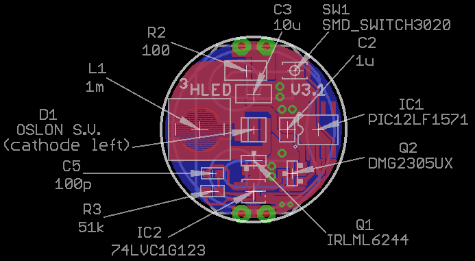
    There's not much difference between V3.0 and V3.1 (just an added switch), but I figured I'd give the latest (and final?) version its own page.  Here's where all the parts go.  Note that it shows an OSLON LED version with a 51k resistor, if you build the Cree XPE2 version, use a 59k resistor (see below).

    Cree XPE2 Green BOM

    The PCBs can be ordered from OSH park.  Cost is $4.10 for three copies.

    Here's a link to a DigiKey cart with all the parts for a single copy using a Cree XPE2 LED.  Cost is $6.40, excluding the case, which you have to buy elsewhere.  The BOM in table form:

    Index Quantity Part Number Description Customer Reference Available Quantity Backorder Quantity Unit Price USD Extended Price USD
    1 1 PIC12LF1571-I/SN-ND IC MCU 8BIT 1.75KB FLASH 8SOIC IC1 1 0 0.58 0.58
    2 1 296-18758-1-ND IC SNGL MONO MULTIVIBTOR SM8 IC2 1 0 0.7 0.7
    3 1 1276-1804-1-ND CAP CER 10UF 25V X7R 1206 C3 1 0 0.26 0.26
    4 1 1276-6469-1-ND CAP CER 1UF 25V X7R 0805 C2 1 0 0.1 0.1
    5 1 311-100FRCT-ND RES SMD 100 OHM 1% 1/4W 1206 R2 1 0 0.1 0.1
    6 1 IRLML6244TRPBFCT-ND MOSFET N-CH 20V 6.3A SOT-23 Q1 1 0 0.54 0.54
    7 1 DMG2305UX-13DICT-ND MOSFET P-CH 20V 4.2A SOT23 Q2 1 0 0.44 0.44
    8 1 BAT-HLD-001-THM-ND RETAINER BATT CR2025/2032 PC PIN B1 1 0 0.28 0.28
    9 1 P189-ND BATTERY LITHIUM 3V COIN 20MM Battery 1 0 0.29 0.29
    10 1 XPEBGR-L1-0000-00F02CT-ND LED XLAMP XPE2 GREEN 525NM 2SMD U$1 1 0 1.86 1.86
    11 1 311-3599-1-ND CAP CER 100PF 50V NPO 0603 C5 1 0 0.11 0.11
    12 1 311-59.0KHRCT-ND RES SMD 59K OHM 1% 1/10W 0603 R3 1 0 0.1 0.1
    13 1 CKN10778CT-ND SWITCH TACTILE SPST-NO 0.02A 15V U$2 1 0 0.25 0.25
    14 1 SRR6028-102YCT-ND FIXED IND 1MH 150MA 4.5 OHM SMD L1 1 0 0.790.79

    OSLON Signal Verde BOM

    The PCB can be ordered from OSH Park.  Cost is $4.10 for three copies.

    Here's a link to a DigiKey cart with all the parts for a single copy.  Cost is $8.03 (excluding case and PCB).

    Index Quantity Part Number Description Customer Reference Available Quantity Backorder Quantity Unit Price USD Extended Price USD
    1 1 PIC12LF1571-I/SN-ND IC MCU 8BIT 1.75KB FLASH 8SOIC IC1 1 0 0.58 0.58
    2 1 296-18758-1-ND IC SNGL MONO MULTIVIBTOR SM8 IC2 1 0 0.7 0.7
    3 1 1276-1804-1-ND CAP CER 10UF 25V X7R 1206 C3 1 0 0.26 0.26
    4 1 1276-6469-1-ND CAP CER 1UF 25V X7R 0805 C2 1 0 0.1 0.1
    5 1 311-100FRCT-ND RES SMD 100 OHM 1% 1/4W 1206 R2 1 0 0.1 0.1
    6 1 IRLML6244TRPBFCT-ND MOSFET N-CH 20V 6.3A SOT-23 Q1 1 0 0.54 0.54
    7 1 DMG2305UX-13DICT-ND MOSFET P-CH 20V 4.2A SOT23 Q2 1 0 0.44 0.44
    8 1 BAT-HLD-001-THM-ND RETAINER BATT CR2025/2032 PC PIN B1 1 0 0.28 0.28
    9 1 P189-ND BATTERY LITHIUM 3V COIN 20MM Battery 1 0 0.29 0.29
    10 1 311-3599-1-ND CAP CER 100PF 50V NPO 0603 C5 1 0 0.11 0.11
    11 1 CKN10778CT-ND SWITCH TACTILE SPST-NO 0.02A 15V U$2 1 0 0.25 0.25
    12 1 SRR6028-102YCT-ND FIXED IND 1MH 150MA 4.5 OHM SMD L1 1 0 0.79 0.79
    13 1 475-3450-1-ND LED OSLON SIGNAL GRN 505NM 2SMD
    1 0 3.49 3.49
    14 1 311-51.0KHRCT-ND RES SMD 51K OHM 1% 1/10W 0603
    1 0 0.1 0.1

    Design Files

    The Eagle design files and a library of all the components used are in the GitHub repo.

  • V3.x Calibration Procedure

    Ted Yapo01/23/2018 at 04:27 5 comments

    I added some code in GitHub for calibrating the V3.x boards.  Since the inductor has a +/-30% tolerance, the brightness and runtime can vary significantly from board to board.  These differences are easily calibrated out by running a little python script I wrote that calculates a calibration table.

    There are just a few steps required to calibrate a newly assembled V3.x board:

    1. Run The Calibrator Image

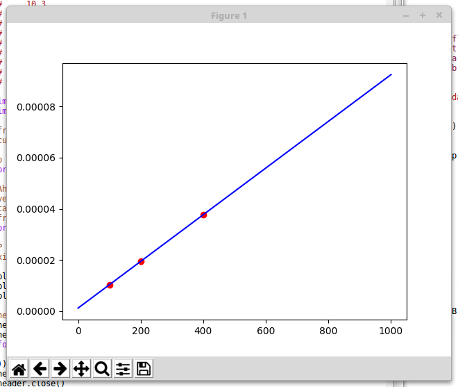
    Download the calibrator.hex image.  This image runs the LED at three different brightness levels, 16 seconds each.  When the image is running, record the currents (in uA) consumed at each brightness.  In one recent test run, I recorded the following:

    10.3
    19.4
    37.7

    These correspond to hard-coded blink frequencies of 100, 200, and 400 Hz.  Save these three current measurements in a file called currents.dat.  The C-code source for this image, calibrator.c, is in GitHub.

    2. Run the Calibration Script

    The python script, calibration.py, reads the currents.dat file you just created, fits a line to current vs frequency, and calculates the frequencies for 1-10 year run times.  The script pops up a window with the plot shown above so you can check the calibration.  All three points should be on the line.  Once you close the plot window, the script generates a header file called modes.h:

    #define N_MODES 10
    struct run_time period_table[N_MODES] = {
      {1, (int)(31000./262.124721 + 0.5)},
      {2, (int)(31000./124.768381 + 0.5)},
      {3, (int)(31000./78.982934 + 0.5)},
      {4, (int)(31000./56.090211 + 0.5)},
      {5, (int)(31000./42.354577 + 0.5)},
      {6, (int)(31000./33.197487 + 0.5)},
      {7, (int)(31000./26.656709 + 0.5)},
      {8, (int)(31000./21.751126 + 0.5)},
      {9, (int)(31000./17.935672 + 0.5)},
      {10, (int)(31000./14.883309 + 0.5)},
    };
    

    3. Compile the Calibrated Hex File

    The tritiled_v30_selectable_runtime.c code automatically includes the generated modes.h file, so you just have to recompile to create a calibrated hex file for the board.  Once you recompile, program the hex image to the board, and it's done.

    If you want, you can verify the current drain for the various modes.

    That's it.  It shouldn't take more than a few minutes to calibrate your board.

    I originally had a script that would do this all automatically, but my PICkit3 has proven to be a little unreliable.  I often have to reset it before it will program correctly.  It could be that my particular programmer is flaky, some incompatibility with linux, or something else, but it was just too frustrating.  The new calibration process is simple, quick, and gives good results, so I'm going to leave it at that.

  • V3.1: Configurable Brightness

    Ted Yapo01/18/2018 at 03:10 4 comments

    I think this is the last version I'm going to make.  I added a tiny (3x2mm) switch to the V3 board to allow you to select the brightness/run-time at startup.  You can see the switch in the upper right, just above the incorrect "V3.0" silkscreen text (I fixed this since these boards were made).  It basically fits in a 1206 footprint! The Cree XPE2 is on the left, with the OSLON Signal Verde LED on the right. I didn't make a V3.1 PCB for the Luxeon C LED.  The Eagle files and gerbers are in GitHub.

    The switch was added to go with the new C-code.  The code allows you to tune the brightness when you first insert the battery.  Pressing the switch cycles between 1-10 year burn rates.  You get a preview of the brightness for 4 seconds, then the LED blinks out the run-time in years (e.g. four blinks = four years).  Once you let it cycle uninterrupted three times, the brightness gets locked in until the battery is removed.

    The code also has some additional enhancements (some are enforced in the makefile).  Most importantly, the code fits into the lower half of flash memory, which is write-protected in the configuration bits.  This prevents accidental over-write of the code by an errant program.  The code has to write to program flash memory to store the brightness mode, since there is no EEPROM on this part.  To make things safer, the brightness mode is stored in the upper half of flash (read/write), with the code itself safely in the lower half.  Microchip probably could have provided a finer granularity on their write-protection (all/none/half), but the part is what it is.

    BOM

    The V3.1 is identical to the V3.0 except for the switch.  This particular switch is available in three different activation forces (100g, 160g, 240g).  I have samples of the 160g and 240g, and am not sure which I like best.  They both seem to work OK:

    (160g) KXT 321 LHS switch, DigiKey part #CKN10778CT-ND, $0.25 each

    or

    (240g) KXT 331 LHS switch, DigiKey part #CKN10779CT-ND, $0.25 each

    Next Up

    I'm still tweaking the automatic brightness tuning script.  I'll be posting that soon.

    I'm also going to run a head-to-head experiment to answer the question: "why don't you just use an LED and resistor".

  • Stupid Case Tricks

    Ted Yapo01/08/2018 at 19:36 2 comments

    Here's a quick rundown on what I have learned from playing with the case:

    TritiLEDs Sink

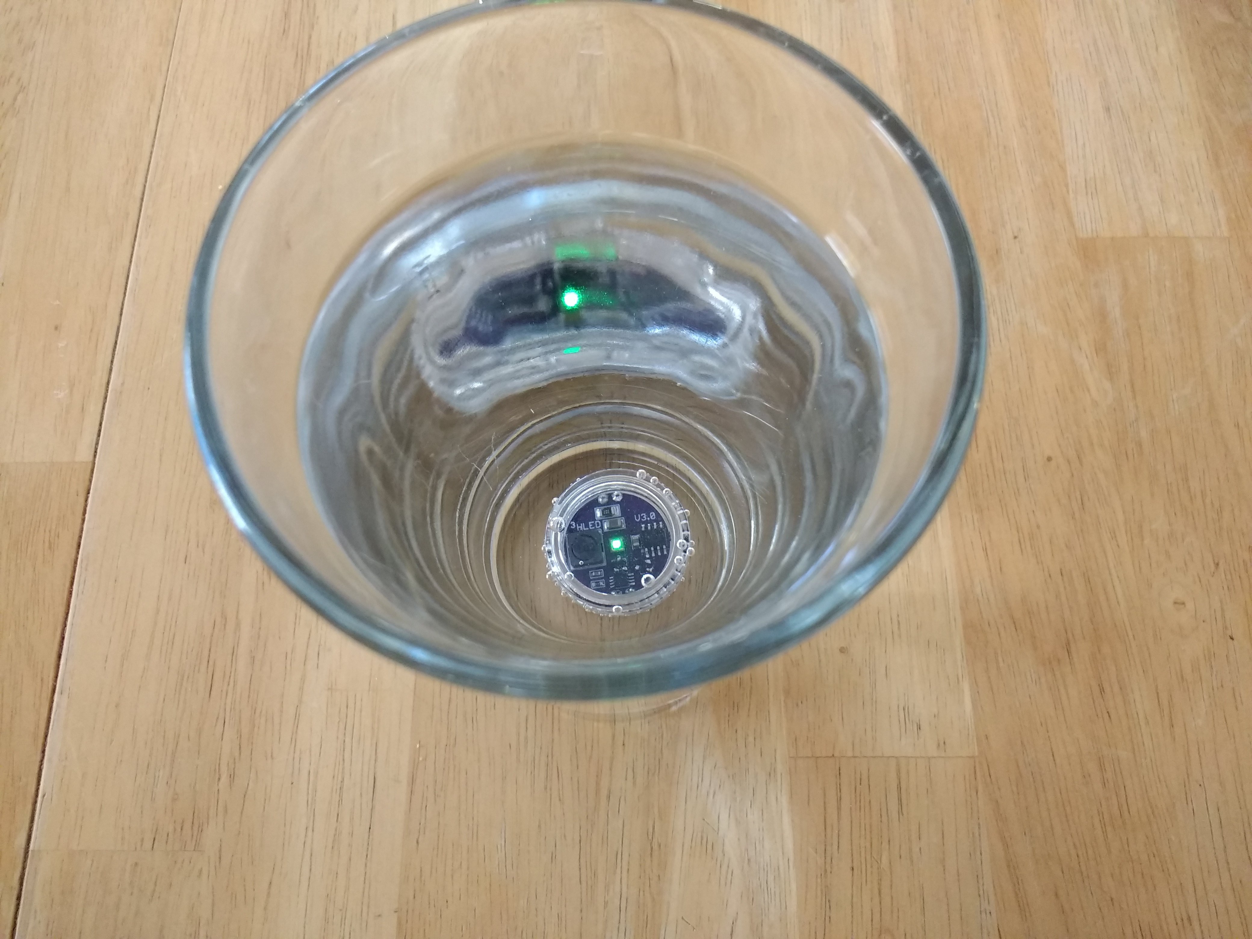
    I had hoped they would float, but I guess that would make the case larger.  This one stayed under water for a day with no leakage.  It was sealed with a 25x1mm o-ring.  The fit isn't very good, though, and I'm going to try to find some better ones.

    Spare Battery

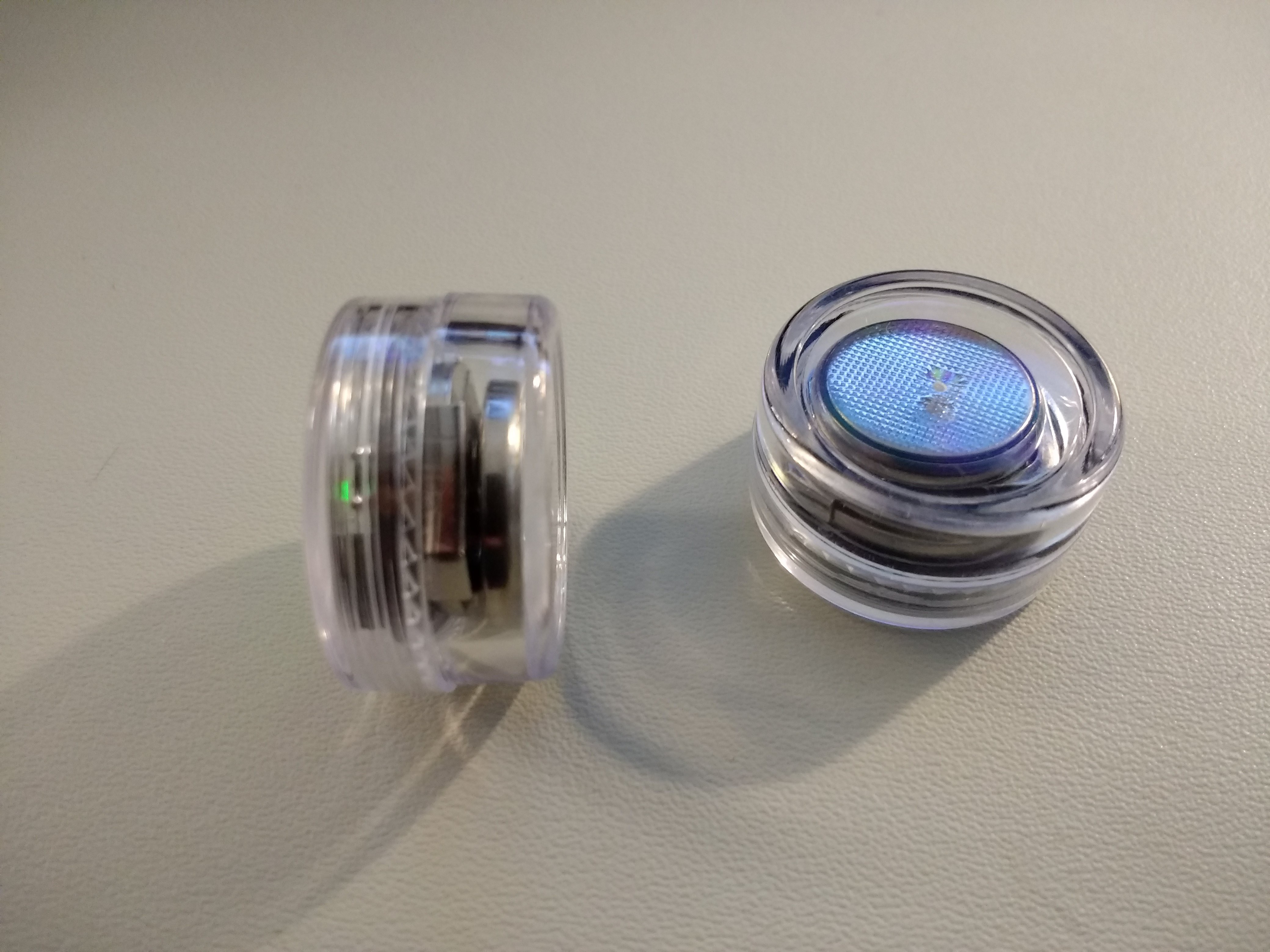
    You can fit a spare battery in the bottom of the case:

    The "5g" jars are a little too deep, and there's just enough space for a spare CR2032.  For 10-year run-times, a spare cell probably isn't too interesting, but for a bright 1- or 2-year marker, having a spare cell right in the case could be handy.

    Magnets!

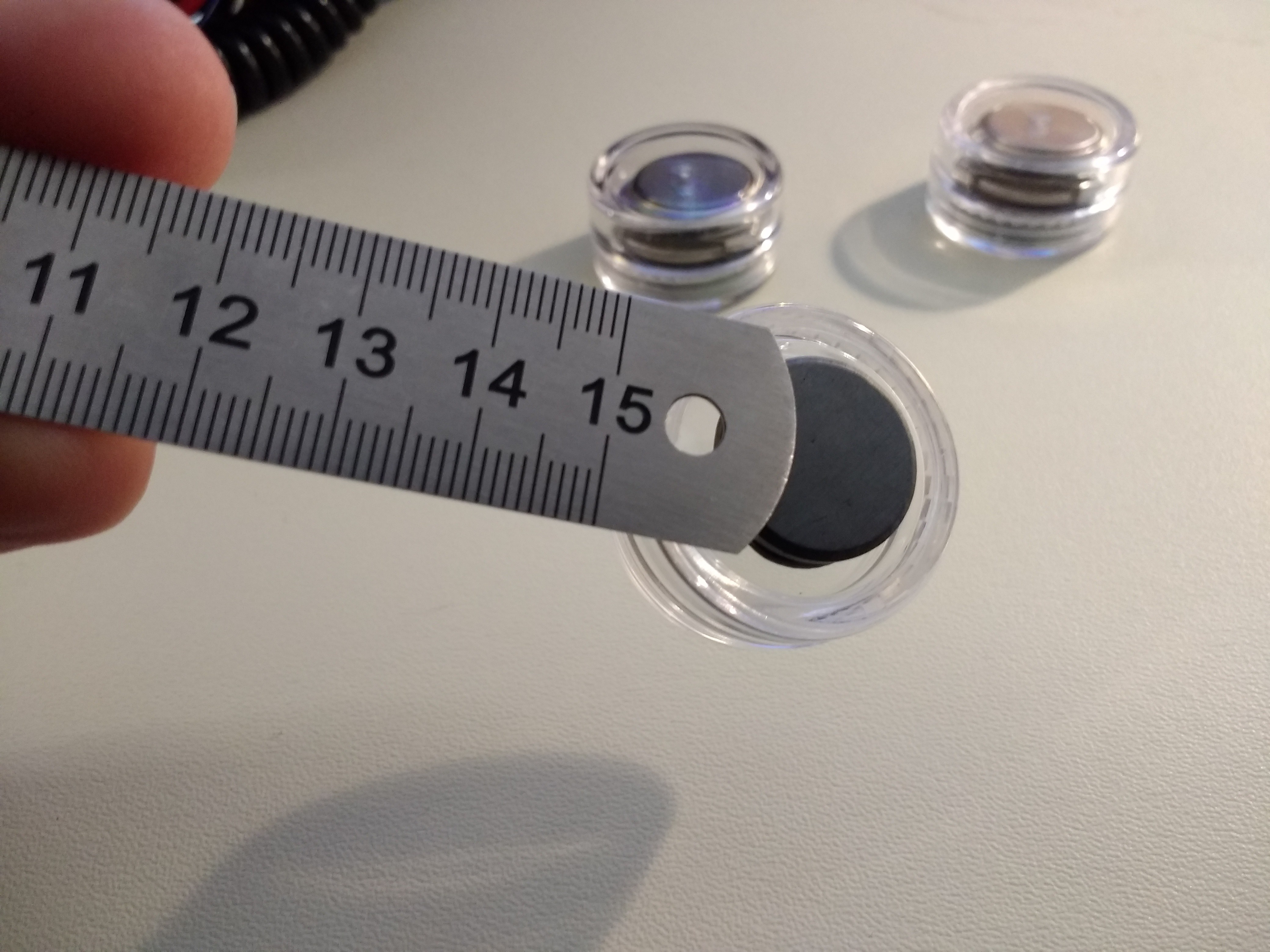
    Like lasers, magnets make everything more interesting.  Here, I glued a cheap 18mm ceramic magnet to the bottom of a case with a dab of epoxy:

    The ceramic magnet isn't very strong, but holds the light OK.  A strong neodymium magnet will hold it without glue, just from being attracted to the coin cell through the case.  The best solution is probably glue+neodymium, but then you might have trouble extracting the PCB to replace the battery.

  • Determining maximum runtime: 17.6 to 20.2 years (CR2032)

    Ted Yapo01/06/2018 at 21:34 25 comments

    OK, so for the coin cell contest, we want to know the maximum runtime.  I have considered estimating this three different ways.  As an example, I'll take the minimum pulse rate of the V3.0, 0.5 Hz (the light blinks once every 2 seconds).  I measured the current drain to be around 1.15uA at this rate. 

    How long will this run on a CR2032?

    First, you need to decide on the cell's capacity.  I'll use 225mAh, which is on the Panasonic CR2032 Datasheet, since I'm using Panasonic cells.  Other manufacturers quote other numbers.

    Capacity / current

    In this method, which you see most commonly used, you divide the capacity of the cell (in Ah) by the current drain of the device (in A), to yield a lifetime in hours. To get years, we divide by 24 hours/day, and 365 days/year (if you want to get technical, you can use 365.25).  In this case, we get:

    0.225 / 1.15e-6 / 24 / 365 = 22.3 years

    Nice, but this exceeds the "shelf life" quoted as 10 years. 

    WTF is shelf life, anyway?  It certainly doesn't mean the battery is dead at that point if left on the shelf.  Instead, it's a measure of self-discharge.  Elsewhere in their Lithium Handbook, Panasonic quotes a 1% self discharge rate per year.  So, at the end of the 10 year shelf life, the cell should retain more than 90% of its initial capacity (depending on 1% of what: see below).  Considering this, the 22.3 years calculated above doesn't seem correct anymore - at that point, the battery would have lost some of its initial capacity sitting on a shelf.  It would be nice to take this into account.

    Considering Self-Discharge

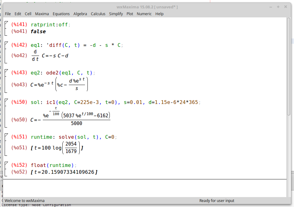
    To include the effects of self-discharge, I first assume the 1% per year means 1% of the remaining capacity.  This means the capacity obeys the differential equation:

    where s is the self-discharge rate, in this case 0.01/year.  The solution of this equation is an exponential decay describing the capacity of a battery on the proverbial shelf, which is interesting, but doesn't answer the question.  To figure the runtime, we also need to include the circuit's current drain.  For the moment, assume the drain is a constant current of d amps.  The equation now looks like:

    In 2018, there's no need to be intimidated by (simple) differential equations like this: just throw them into Maxima.

    I got maxima to solve the ODE, selected a specific solution by giving the initial conditions (fresh battery at t=0), and finally solved the result for the time when C=0.  The result: 20.2 years.  Two years shorter than the earlier estimate. (Note: earlier, I posted 19.4 years here due to a typo in the maxima code).

    Linear Self-Discharge

    It's also possible that 1% discharge per year means 1% of the initial capacity per year.  This would mean a linear decay of capacity obeying:

    The solution to this one is trivial: we just add (0.225 Ah * 0.01 / 365 / 24) = 257nA to the device current.  For the lifetime, we get 0.225 / (1.2e-6 + 257e-9) / 24 / 365 = 17.6 years.  Two and a half years shorter still.

    So, there you have it: the TritiLED V3.0 can run for somewhere between 17.6 and 20.2 years on a CR2032.

    There's a subtle problem with each of these estimates.  When the cell voltage falls over time, the circuit current also falls.  This would extend the run-times, since the current is continually dropping.  Ignoring this effect would tend to under-estimate the run-time, so the above estimates may be slightly conservative....

    Read more »

  • Selecting brightness/battery life at runtime

    Ted Yapo01/06/2018 at 19:16 2 comments

    The simple assembly code I wrote to get V3.0 up and running works fine.  You can configure the brightness in code, then download a new image to the PIC to change the battery lifetime.  This is OK if you are building these devices for your own use, but inconvenient for people who just want to buy them.  So, it would be nice to have a simple user interface on the board to select the runtime.

    I was initially concerned that the runtime might get accidentally changed over the years, then @jaromir.sukuba suggested a configuration mode that was only accessible briefly after the battery was inserted.  After that period, the brightness (and battery life) are locked-in until you remove the battery.

    I wrote some C code that does this yesterday - you can see it in the GitHub repo.  Well, it's mostly C-code.  There are two helper functions I had to write in assembly to access the high-endurance flash (HEF) portion of program memory to store the current mode setting.

    The user interface is simple.  After inserting the battery, the LED blinks out the runtime in years: 5 blinks = 5 years, etc.  To increment the runtime, you short pin 4 to pin 8 (RA3 to GND).  This "switch" is properly debounced in software.  I found some 2.6x1.6 mm switches, and I think I'm going to spin a set of V3.1 boards with them.  The code blinks out the runtime 10 times, then enters the running mode, and can't be re-configured without removing the battery.

    The only downside to this approach is that you sometimes have to wait a long time for the capacitors to discharge.  At 10-year run-times (or more), the mere 11uF of capacitance on board can power the LED for many seconds!

    There are a few configurable parameters in the code controlling the interface:

    // number of cyles of blinks to show before exiting config mode
    #define N_CYCLES 10
    
    // number of pulses per "blink" in config mode, higher = brighter blinks
    #define N_PULSES 10
    
    // year run-times and corresponding PWM periods
    #define N_MODES 10
    struct run_time
    {
      uint8_t years;       // number of years of run-time or mode number
      uint16_t pwm_period; // PWM period (in units of 1/31000 s)
    };
    
    // Note: frequencies converted to pwm periods
    const struct run_time period_table[N_MODES] =
      {{1, (int)(31000./326. + 0.5)},
       {2, (int)(31000./155. + 0.5)},
       {3, (int)(31000./98. + 0.5)},
       {4, (int)(31000./69. + 0.5)},
       {5, (int)(31000./52. + 0.5)},
       {6, (int)(31000./41. + 0.5)},
       {7, (int)(31000./33. + 0.5)},
       {8, (int)(31000./27. + 0.5)},
       {9, (int)(31000./22. + 0.5)},
       {10, (int)(31000./15. + 0.5)}
      };
    
    // default mode index 
    #define DEFAULT_MODE_IDX 1
     

    The run-times and associated PWM frequencies are stored in a table in the flash.  In this case, you can select from 1 to 10 year lifetime in 1-year increments. These values can be manually determined, or you can use a script and some hardware to find them automatically (I'll be publishing this script soon, I'm just cleaning it up now).  The table shown here is not quite right: there is no need for the frequencies to be integers. Frequencies with greater precision (e.g. 21.7 vs 22), will result in more accurate PWM period counts (e.g. 1428 vs 1409).  The differences can be significant for multi-year run times.

    I guess I just promised at least two more logs: the auto-tuning script, and V3.1 PCBs with a tiny switch.  It might feel like work if I didn't love it :-)

  • V3.0 Release

    Ted Yapo01/03/2018 at 15:02 1 comment

    I've finished the design and tuning for the OSLON Signal Verde LED flavor of V3.0.  The design is documented here; as I tune the other LED flavors, I'll add to this log.  Key features of V3.0 are the ability to finely tune the brightness/lifetime trade-off, build-time configuration for different optimal LED drive currents, and using a "5g" plastic jar as a case.

    The PCB uses a through-hole CR2032 holder (smaller than the SMT version), allowing it to fit in the jar.
    Circuit

    The V3.0 circuit uses a 74LVC1G123 monostable to produce short, accurate pulses for ramping up current through the inductor.  The inductor size and monostable pulse width are selected to optimize the drive current to the LED, based on measured LED efficiency vs current.  A PIC12LF1571 uses two synchronized PWM outputs to control the pulses.  One PWM gates power to the monostable (it consumes too much quiescent power), while the second PWM triggers the pulse.  The 16-bit PWMs on the PIC allow very fine tuning of pulse frequency and hence battery lifetime vs LED brightness.  Combined with inductor and monostable resistor selection, the circuit lets you tune for very good electrical and LED efficiency while allowing accurately tunable runtime.

    Note: a different value of R3 is required for each type of LED.

    Bill of Materials

    The following components are required for any flavor of V3.0:

    Depending on the LED you choose, you will need a different PCB, resistor, and possibly inductor.  Choose from one of the LEDs in the following sections:

    OSLON Signal Verde (505nm)

    This LED has the best optical match to dark-adapted eyes.  If you are just going to build one version, use this LED, and forget about the $3.49 price tag. It requires a 1mH inductor and 51k resistor for optimum efficiency.

    Luxeon C Cyan

    This LED is my second choice for dark-adapted eyes.  It's cheaper than the OSLON at $2.74, but just a little too blue for optimum visibility.  The higher optimal current also makes it flash more visibly at extended run-times (see below).

    Read more »

  • First V3.0 PCB

    Ted Yapo01/03/2018 at 03:44 5 comments

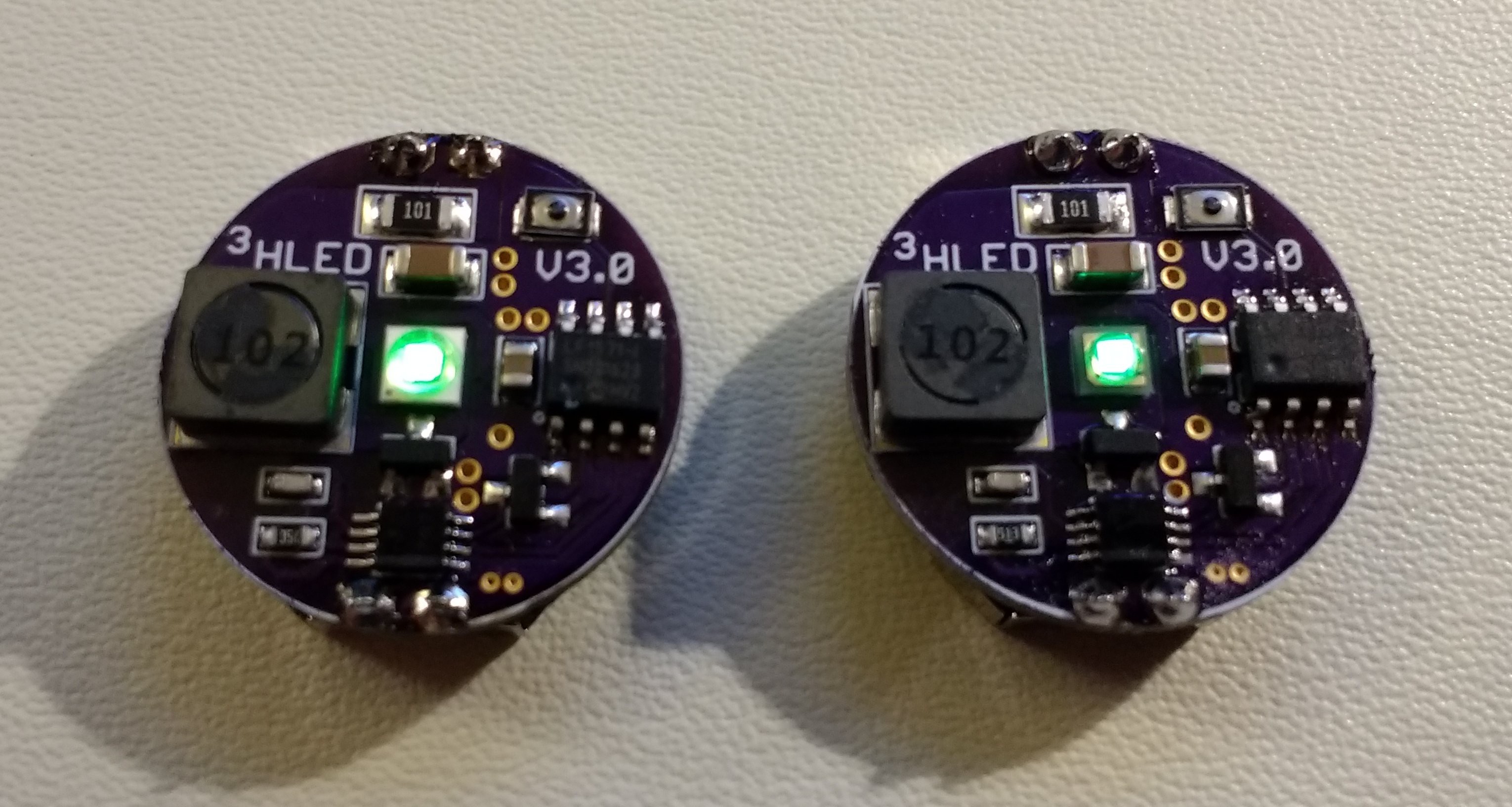
    I populated the first V3.0 PCB today.  It's actually been through a few iterations, but I didn't even bother filling any of the earlier boards.  This one is finally worth building.  The board is smaller now (23mm diameter), so it fits inside cheap, widely available "5g" polystyrene jars, but still uses an inexpensive replaceable CR2032 for power.

    This first PCB uses an OSLON Signal Verde LED.  I tuned this particular PCB to a 2-year run-time (12.5 uA) on a CR2032, and it blinks at 157 Hz.  The breadboarded version needed to be tuned to 123Hz to achieve the same run time (probably due to the 30% inductor tolerance).  The ability to fine-tune the current draw was one of the design goals of the V3 (as was fitting inside these jars).

    I also have PCBs for Luxeon C and Cree XPE / Cree XPE2 LEDs.  They are identical to this one except for the LED pads.

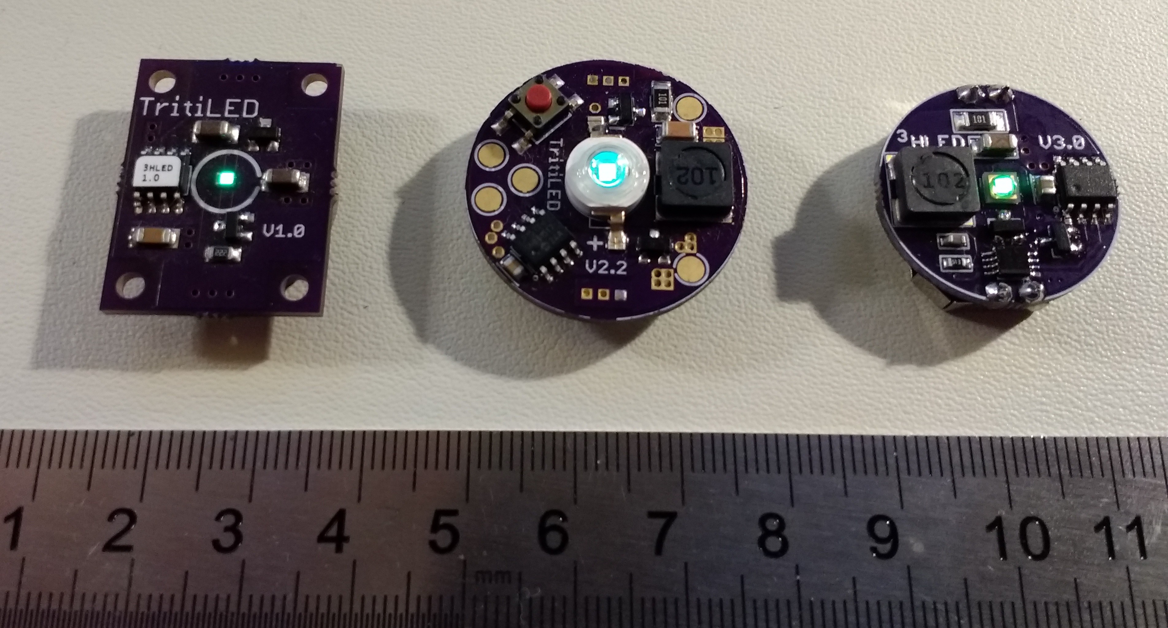
    Here's a visual comparison with the previous two generations for reference:

    One of the key differences is the use of a through-hole CR2032 holder, which is actually smaller in diameter than the surface-mount version (since the through hole doesn't need flat mounting tabs).  This was the final change required to fit the PCB inside the jar.

    Tuned to the same 2-year run time as the V2.0, the V3.0 is noticeably brighter.  It's roughly as bright as the V1.0 (which only runs 1 year).  But, you can tune the V3.0's brightness to last from less than 1 to more than 10 years on a CR2032 cell.

    I'll put together a more detailed post for those wanting to build some of this new version, including a BOM and placement diagram.  The PCB designs are already in GitHub, I just need to polish the software a little and put it up there.

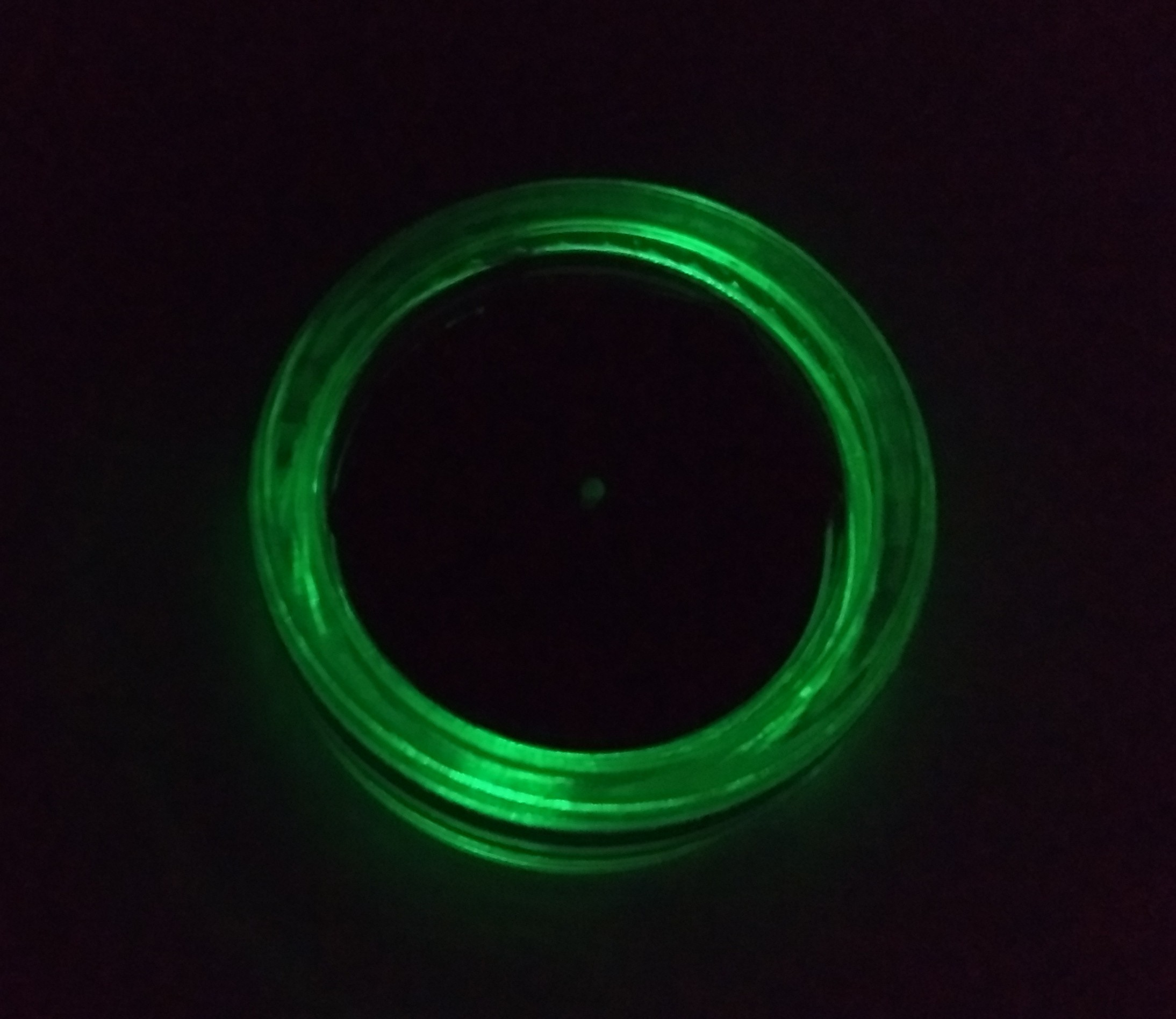
    EDIT: I discovered that the clear jar makes a nice dim ring of light when placed upside down.  I usually keep a few of these lights on my nightstand, but the light can actually be enough to bother me.  Being able to attenuate the output somewhat by turning them upside down is an added bonus, especially since it looks so cool.

  • Programming PICs with Python

    Ted Yapo12/31/2017 at 04:09 8 comments

    No, not *in* python; they're still coded in assembly.  I mean using python to drive the assembler and PICkit3 programmer.  It turns out that MPLABX tools have a decent command-line interface.  I wrote some simple python classes to take the pain out of the command-line switches and enable automatic tuning of V3.x TritiLEDs.

    One of the problems with the V2.x design was the inability to fine-tune performance for variations due to part tolerances (the inductor, for example is +/-30%).  Since the pulse frequency of the V3.x design can be very accurately tuned, I would like to be able to "tune out" the component tolerances once the devices are assembled.  This calibration process means programming the part, measuring the current drain, adjusting the pulse frequency, recompiling, and re-programming.  Then, maybe looping through the whole process a few times.  This is not something I want to do manually for each unit.

    So, that's where the python comes in.  The fundamental code is shown below.

    Scripting the MPASMX assembler is trivial.  In order to tune the frequency parameter, I simply write a one-line include file from python including an "equ" directive.  This file is included by the main assembly file.

    Scripting the PICkit3 programmer is much more interesting.  You control the programmer through a script called "ipecmd.sh" (check for the name on different OS's), and it's documented in a file called "Readme for IPECMD.htm" in the mplabx/docs directory The programmer has provisions for powering the target device directly, and allows you to adjust the Vdd voltage.  Coupling this with a serial-enabled DMM makes a very nice little test kit: you can program different code on the device, then measure the current drain over a range of supply voltages.  There are probably a lot of interesting uses.

    I still have to integrate the DMM code and write the iterative tuning algorithm, but that's probably of less general interest than programatically driving the PICkit3.

    One thing I've discovered so far is that the output voltage of the PICkit3 doesn't seem very accurate.  I may add another serial-DMM to the test setup to measure the actual voltage instead of relying on what I tell the programmer to supply.

    #!/usr/bin/env python
    
    import subprocess
    
    mplabx_path = '/opt/microchip/mplabx/'
    
    class MPASM:
      def __init__(self, path):
        self.path = path + 'mpasmx/mpasmx'
      def assemble(self, filename):
        subprocess.call([self.path,
                         filename])
    
    
    class PICKIT3:
      def __init__(self, path, part):
        self.path = path + '/mplab_ipe/ipecmd.sh'
        self.part = part
      def program(self, hexfile_name, voltage):
        subprocess.call([self. path, 
                         '-TPPK3',
                         '-M',
                         '-F' + hexfile_name,
                         '-P' + self.part,
                         '-W' + str(voltage),
                         '-OL'])
      def setVoltage(self, voltage):
        subprocess.call([self. path, 
                         '-TPPK3',
                         '-P' + self.part,
                         '-W' + str(voltage)])
    
    class Frequency:
      def __init__(self, filename):
        self.filename = filename
      def set(self, freq):
        f = open(self.filename, 'w')
        f.write('FREQ    equ    .' + str(freq))
        f.close
    
    voltage = 3.2;
    PK3 = PICKIT3(mplabx_path, '12LF1571')
    ASM = MPASM(mplabx_path)
    freq = Frequency("frequency.asm")
    
    
    freq.set(123)
    ASM.assemble('tritiled_v30.asm')
    PK3.program('tritiled_v30.HEX', voltage)
    #PK3.setVoltage(1.8)
    

View all 44 project logs

Enjoy this project?

Share

Discussions

aaaaaa wrote 02/09/2023 at 15:06 point

one simple questions.

Why not add a light sensor and periodically turn the lights off or down when it's bright enough?

  Are you sure? yes | no

--Oz-- wrote 09/20/2022 at 19:41 point

@ Ted, you ever think about a regenerative snubber for the wasted energy after LED current has stopped (the drain ringing energy)? It could add some time to your project? Or are you done with this project?

  Are you sure? yes | no

Jeff Baker wrote 06/18/2021 at 17:32 point

Nice project!  I wonder, though, why you don't drive the LED mosFET gate directly from the PIC PWM.  Are the required pulses too short to get good PWM resolution?

  Are you sure? yes | no

KSUdoubleE wrote 06/02/2020 at 20:53 point

My first battery died back in April.  It made it 2.5 years!

  Are you sure? yes | no

D Kearns wrote 11/20/2018 at 19:40 point

I've built a couple up and they are working well.  I'm curious how to calculate R3 for a different LED.  Took me a bit on a windows box to get it to compile.  I really like this project. Thanks for the well commented code.

  Are you sure? yes | no

Ted Yapo wrote 11/20/2018 at 20:11 point

The procedure to come up with an "optimal" value of R3 for a given LED is a bit complicated.  First, you need to measure the brightness vs current and voltage characteristics of the LED to find its efficiency curve (see https://hackaday.io/project/11864/log/71858-version-3-beginnings).  From this, you can determine the optimum peak current for a sawtooth waveform drive, like the inductor will produce.  Then, you typically have to trade off between electrical and electro-optical efficiencies (see https://hackaday.io/project/11864/log/72034-tuning-v30).

If that sounds like too much trouble, here's a possible shortcut.  You can probably get a good idea of the optimal value of R3 by comparing the LED brightness to one driven from the same cell current at DC.  For example, say you want a 2-year run-time from a CR2032, which equates to roughly 12.5uA drain at 3V.  Hook up an LED with a potentiometer and 3V source and adjust the pot to give 12.5uA into the LED (watch out for meter burden here).  Now, use another pot at R3, and adjust the resistance value (start with around 50k for simlarly-sized LED dice).  Once you choose a candidate R3, you'll need to adjust the PWM frequency until the current drain gets to 12.5uA.  Now, you can compare the brightness with the DC LED.  If you make 2 tritileds, you can use one as a reference to test new R3 values on the other one.

If that seems too complex, just use something like 56k for any LED you choose :-)

  Are you sure? yes | no

Ted Yapo wrote 11/20/2018 at 20:12 point

oh, post a picture if you can - I like to see these things in the wild

  Are you sure? yes | no

NobodyYouKnow wrote 04/27/2018 at 12:25 point

I've built a handful of these as night-time accent lights. I put them near hard-to-see edges, and Presto! No more stubbed toes or banged elbows. Plus they are easy and fun to build. I personally use high temperature PTC heaters and a "manual" reflow profile for everything except the battery clip. It works every time.

Thanks, Ted. This is an awesome project.

  Are you sure? yes | no

Ted Yapo wrote 04/27/2018 at 12:37 point

Thanks, I'm glad you've enjoyed it.

Do you have any more info on using PTC heaters for reflow?

  Are you sure? yes | no

NobodyYouKnow wrote 04/30/2018 at 12:11 point

Imagine the most robust, precise, reliable and automated way to reflow PCBs. What I do with a PTC heater is the exact opposite. :-)

I bought a couple of 120v aluminum clad high temperature PTC elements, placed them side-by-side on a heatproof mat, and wired them directly to a power cord. Put the populated PCB on top and plug them in. When the reflow happens, I nimbly (because no other way works) lift the PCB with tweezers and place it on a cool surface. Voila! It works well enough for smaller projects. I have no illusions it will scale larger. It's two advantages are 1) that it is simple and cheap, and 2) it really appeals to my inner hacker to make something like this work.

  Are you sure? yes | no

Ted Yapo wrote 04/30/2018 at 13:36 point

@NobodyYouKnow lol.  Next time I have a fire outside, I'm going to reflow a few boards in between toasting marshmallows.

  Are you sure? yes | no

NobodyYouKnow wrote 05/01/2018 at 11:40 point

Ooohhh! Reflowing marshmallows! I can work with that!

  Are you sure? yes | no

derek.bever wrote 04/26/2018 at 15:12 point

These are super cool. I've built a couple of them, they're pretty impressively bright. I picked these to build specifically as a great project to give people to practice their SMD soldering, and it fits the bill nicely - inexpensive to put together, but actually a useful project. Great work!

https://imgur.com/a/lepv4Br

  Are you sure? yes | no

Ted Yapo wrote 04/26/2018 at 18:48 point

Awesome!  Do you solder the LEDs with an iron?  I didn't think it was possible, and that you'd have to extend the pads to be able to do it.  I've only used hot air or a skillet.

Yeah, believe it or not, I've had people asking for dimmer ones.

  Are you sure? yes | no

derek.bever wrote 04/26/2018 at 18:55 point

I did the LED and inductor with hot air, but everything else is fair game. My coworker just put one together this morning and it worked on the first try.

  Are you sure? yes | no

Ted Yapo wrote 04/26/2018 at 21:59 point

@derek.bever 

Then I need to make the next one more difficult :-)

  Are you sure? yes | no

David S wrote 01/26/2018 at 22:34 point

I really can't tell you how much I love this project. I got a couple tritiled's from kontakt and plan on making at least a couple more myself. Have you considered using UV LEDs and glow in the dark powder? It's a road I hope to go down towards the end of summer, but I'm curious if you've looked into it or have any thoughts on things to consider.

  Are you sure? yes | no

Ted Yapo wrote 01/26/2018 at 22:57 point

I'm glad you're enjoying the project!

I did try a UV LED and some random glow-in-the-dark plastic I had laying around.  It wasn't very good, and seemed much less bright than just a cyan/green LED.  I have some activated ZnS powder that I keep meaning to try, but haven't yet.  Maybe that would be better.

Sort of related, I did try IR LEDs with a night-vision monocular.  The 850nm LEDs were awesome.  Normally, I can just barely see 850nm LEDs with the naked eye, but at these levels, it's completely invisible.  It lights up as a very bright marker in the viewer, though.

  Are you sure? yes | no

PointyOintment wrote 10/08/2018 at 11:07 point

It probably works less well because the phosphor takes in the pulses (which appear brighter to the human eye than their average power would suggest) and puts out CW (which doesn't). Also, of course, phosphors aren't 100% efficient.

  Are you sure? yes | no

Mike Harrison wrote 01/05/2018 at 14:49 point

That inductor looks way oversized for the currents involved - you might get a tiny advantage from lower DCR but should be able to use something a lot smalller with negligible performance loss.

Also you may find that a white LED ( with high colour temp) will give more light at low currents.

  Are you sure? yes | no

Ted Yapo wrote 01/05/2018 at 15:28 point

Yes, I agree, the inductor looks way oversized. Except that there are only (25) 1mH inductors stocked by DigiKey that are shorter.  I have horizontal board space (dictated by the battery), but am short on height, so to speak.

Of the 25 shorter ones I can find:

https://www.digikey.com/products/en/inductors-coils-chokes/fixed-inductors/71?k=inductor&k=&pkeyword=inductor&pv7=3&pv7=2&FV=1140003%2C1f140000%2Cmu1mH%7C2087%2Cffe00047&mnonly=0&ColumnSort=1500&page=1&stock=1&quantity=0&ptm=0&fid=0&pageSize=50

The next best one for DCR is 6.5-ohm (but is the same footprint and only 0.2mm shorter) and costs $1.23 vs  4.5-ohm and $0.74.  The shortest ones they have are 2.0mm high (vs the current 3mm), and the best of those is 11.5-ohm DCR for $1.79.

If I'm willing to go to a 31.5-ohm DCR, I can get a 1007-smt package one, but I think that would really take a toll on the efficiency: a quick simulation shows 30% loss vs 5%.

1mH is a large inductance, and you just don't find great ones, but I think this particular one is in a sweet spot for height, DCR, and cost.

If you could generate much shorter pulses (efficiently) to drive the MOSFET switch, you could use smaller-valued inductors to get the currents required, but that has proved elusive so far.

I've tested a bunch of white LEDs, and the phosphors don't seem to work well at low currents.

The bigger problem is that light away from the eye's response peaks (505 or 555nm depending on dark adaptation) is wasted in this application.  White LEDs are useful for seeing objects in color, but where you'd care to put a glow marker, your eyes won't see color anyway, since they'll be dark-adapted.

  Are you sure? yes | no

Simon Merrett wrote 01/05/2018 at 22:50 point

Hi @Ted Yapo, I'm probably way out of my depth here but I'm using the 2.2mH part from the Bourns SRF3216 series, which is apparently available on digikey in the US (https://www.digikey.com/products/en?keywords=SRF3216). Could you make use of these? They appear to have inductance in the range you are considering and low DCR. They're tiny too. 

  Are you sure? yes | no

Ted Yapo wrote 01/06/2018 at 02:35 point

Hi @Simon Merrett , that's an interesting part you have there.  It's clearly intended as a common-mode choke to filter noise, more akin to a transmission-line transformer than a power inductor, but maybe you found a hidden gem.

My suspicion is that the core is lossy, which is what you want for noise suppression, but I could be surprised.

Which specific part number are you using?  The datasheet lists impedance vs frequency, but doesn't list inductance values - that makes me think a good portion of that impedance is real, as in resistive, as opposed to imaginary, as in inductive (reactance).

They're cheap enough that I can throw a few in my DigiKey cart and test them out.  The size is certainly very nice :-)

  Are you sure? yes | no

Simon Merrett wrote 01/06/2018 at 08:08 point

@Ted Yapo here's the link to the part where I bought it (they might have mis-categorised it) https://uk.rs-online.com/web/p/wire-wound-surface-mount-inductors/8118777/

BTW, if I was selecting for core lossiness (?), is there anything apart from the physical size of the core that I could look for in the specs to give me a clue whether it is high or low loss? 

Would be great to see you characterise this part as it would help me understand what's going on in the current and next planned version of #Yapolamp.

  Are you sure? yes | no

Ted Yapo wrote 01/06/2018 at 14:19 point

@Simon Merrett Thanks for the link.  I found them at DigiKey and added 10 to my cart.

Loss is a function of core size (for saturation issues) and wire size (DCR), but also of core material, which isn't often listed on inductor datasheets.  Saying the core is "ferrite" gives you about as much information as saying it's "wood" vs "metal" (e.g. is it balsa or oak?) There many ferrites with very different properties - some more suited to power inductors, others useful at RF, etc.

  Are you sure? yes | no

Simon Merrett wrote 05/01/2018 at 18:12 point

Hi @Ted Yapo I'm about to start work on a #Yapolamp  update and wondered if you'd had a chance to look at these tiny inductors yet. My son loves his one he got for Christmas. We set it on "bright" mode on his nightstand every evening when we turn the lights out and it's still glowing on "always on" in the morning. Then, through the winter, he's turned it back onto bright and used it to navigate the landing to our bedroom on dark mornings. We charge it up once or twice a week, depending on how much he's played with it. My daughter has one at the top of her birthday list, so I thought it would be a good time to iterate the design!

  Are you sure? yes | no

Ted Yapo wrote 05/03/2018 at 12:10 point

@Simon Merrett I did get a few of these to test, but they quickly got lost in the parts bin.  I'll have to dig them out and have a look :-)

  Are you sure? yes | no

Simon Merrett wrote 05/03/2018 at 17:02 point

That would be brilliant, thank you.

  Are you sure? yes | no

crjeder wrote 11/30/2017 at 07:20 point

Have you considered entering the Coin Cell Challenge? 

https://hackaday.com/2017/11/29/coin-cell-challenge-use-coin-cell-win-prizes/

  Are you sure? yes | no

Simon Merrett wrote 11/30/2017 at 13:29 point

+1

  Are you sure? yes | no

Ted Yapo wrote 12/04/2017 at 01:59 point

Thanks for the heads-up on the challenge.  It's tempting, and maybe I'll enter some variation of the idea.  There's a version I've been meaning to make that's much larger and more expensive, but also more efficient and longer-running.  It's not practical, really, except maybe for a contest...

  Are you sure? yes | no

crjeder wrote 12/04/2017 at 14:23 point

Go for it! If this were a public vote contest you would have mine!

  Are you sure? yes | no

KSUdoubleE wrote 08/18/2017 at 17:04 point

Nice project!  I made it last week, etched my own board so I had to arrange things somewhat differently to reduce vias since I don't do through hole plating.  I also used a 12LF1501 instead for the processor because I had some around.  Took a little tweaking in the code as it doesn't have a OSCCAL register, but it is working well.  Good job matching the glow/color.

  Are you sure? yes | no

Ted Yapo wrote 09/04/2017 at 16:44 point

I'm glad you found it interesting/useful.  Post a picture if you get a chance - I really like to see these things in the wild.

Having OSCTUNE doesn't give you that much control - just a fine tuning, really.

  Are you sure? yes | no

KSUdoubleE wrote 09/08/2017 at 19:30 point

  Are you sure? yes | no

Ted Yapo wrote 09/08/2017 at 23:47 point

Awesome!  I think that's my favorite build yet.  Do you mind if I post the images in a build log?  I'd like to make a gallery of builds done by others.

  Are you sure? yes | no

KSUdoubleE wrote 09/11/2017 at 13:27 point

Sure that is fine.  Thanks again for sharing your project!

  Are you sure? yes | no

bulrush15 wrote 07/17/2017 at 12:50 point

Ted, would you consider selling a kit we can solder together? I don't know how much shipping is now for Digikey but it's normally outrageous for companies like that. 

  Are you sure? yes | no

Ted Yapo wrote 07/17/2017 at 14:11 point

Digikey will ship packages under 8 oz for $3.39 by USPS first class mail, and 1 lb by USPS priority mail for $7.50.  I've used both, and you get a *lot* of SMT components per pound.  You have to order the OSH Park PCBs in multiples of three ($6.15/3), so let's say you order enough parts to build three of them.  That costs maybe $26 with shipping from DigiKey.  So, you might pay $33 for all the parts for 3 of them - $11 each, including shipping.  Rough numbers.

  Are you sure? yes | no

bulrush15 wrote 07/14/2017 at 20:23 point

Have you considered these low-power circuits for powering an LED? From Don Klipstein, the guru of lighting. http://donklipstein.com/ledlocup.html. I thought it might provoke a brain storm.

Another interesting link, ultra-low power circuits: http://www.discovercircuits.com/M/micropow.htm

  Are you sure? yes | no

Ted Yapo wrote 07/14/2017 at 22:23 point

There might be something to the first link.  It's interesting stuff, but not knowing how bright he's trying to go for, I'm not sure how to evaluate it.  The basic idea of using PWM at more efficient LED currents is the same, just achieved by different means. Other than that, a few points come to mind:

1. It's a higher voltage source 9V in some cases, 5 in others.  I'm not a big fan of 9V batteries.  They're huge, and even though they're available in LiFeS2 chemistry, the energy density is still lousy.  

2.  The "excess" voltage seems to be dropped across a resistor.  This jumps out as inefficient, but maybe not that bad.  This also won't work when the battery voltage dips below the Vf of the LED.

3. Because of the 9V supply vs 3V, you need to multiply the quoted currents by a factor of 3 to compare with operation from coin cells.  The 45 uA current at 9V is equivalent to 135 uA at 3V from a power standpoint.  This is more than 10x the power of the standard V2.2 TritiLED.  Again, I don't know how much light the two put out compared to each other - maybe I need to build one of the circuits from that link.  On the other hand, I think the TritiLED output is probably sufficient for the intended purpose as-is.

4. Just as a point of reference, the circuits described on that page consume around 40uA from a 9V source.  A 9V LiFeS2 battery has about 750mAh of capacity, so would run such a circuit for about 2.2 years.  This is about 6 months shorter than a V2.2 TritiLED runs off a CR2032.  Again, no idea about the brightness comparison, but a 9V battery is huge compared to a CR2032.  The TritiLED would theoretically run for 47 years on 2x lithium AA cells (about the size of a 9V) - but the battery only has a shelf-life of 20 years, so let's say 20+ years.

The second link has some interesting circuits.

  Are you sure? yes | no

crjeder wrote 07/11/2017 at 14:27 point

Just read about your Project with great interest. Thank You for posting this online!
I can't get one thing out of my mind, though: wouldn't an electroluminescence device work better for efficient dim lighting than an LED?

  Are you sure? yes | no

Ted Yapo wrote 07/11/2017 at 14:49 point

I haven't really explored EL devices for this application, but my understanding was that modern LEDs had an efficiency advantage - and they're constantly improving, driven by the LED lighting industry.  I can't find solid efficiency data though.  My understanding was that LEDs were now the efficiency king, having surpassed fluorescent tubes some time ago.

The short half-life of EL devices (quoted as 3k hours here: https://focuslcds.com/journals/el-backlights-vs-led-backlights-legacy-display-technology-vs-cutting-edge/ ) would be a concern. I've seen this happen with plug-in EL night-lights; they don't last very long. The shortest-lived markers I'm considering these days run for 2 years (18k hours), which is (6)  3k hour half-lives - I'd expect the EL to be completely burned out by the end.  You might get longer life at lower current, but the same is true for LEDs, which get a 50-70k half life estimate at nominal currents.  On the other end, I have some devices intended to run 10 years, and am playing with ideas about 20-25.  I suspect that LEDs have a huge advantage here.

There's the necessity of high-voltage to drive them - this complicates the board, and might create safety concerns.

Finally, I don't see small EL "dots" being widely available.  LEDs are easy to source - especially for the amateur/maker/etc.

I'm open to the idea, but have doubts about all of these issues.  Maybe I'm ill-informed: what are your thoughts?

  Are you sure? yes | no

crjeder wrote 07/11/2017 at 15:13 point

I was asking because you are have definitely more knowledge than me. What I understood is that EL has a higher theoritic limit on efficiency and is long lifed. An other advantage might be that it can be of any shape (just cut the sheet as needed). I was thinking that LEDs are efficient only on the high end (high lumen). But I may be wrong. Have to dig out the efficiency claims of EL...

The driver (DC to AC converter and high voltage) was the main reason I belived that the efficiency for the whole device in the battery operated case is to bad. But again: I don't know and was just asking because you might know..

  Are you sure? yes | no

Ted Yapo wrote 07/11/2017 at 15:37 point

I don't have too much experience with EL - so there may be something to this.

A quick scan reveals that even the EL manufacturers quote about 10x the lifetime for LEDs than EL.  Maybe at super-low power, they both last long enough anyway?

As for the efficiency, this page claims 6 lumens/watt for EL panels:

http://www.edisontechcenter.org/electroluminescent.html

while this Luxeon-C LED claims 76 lumens/watt:

https://www.digikey.com/product-detail/en/lumileds/L1C1-CYN1000000000/1416-1917-1-ND/5872100

Maybe there are better numbers for EL panels somewhere?  I have seen it mentioned that they are more efficient than LEDs for low brightness applications, but this whole project came about because using LEDs naively for low-brightness is very inefficient.  You are correct - with DC drive, LEDs *are* only efficient at the high brightness end.  By driving them at higher currents near peak efficiency with a low-duty-cycle PWM, though, you can regain much of this efficiency.  They're bright and efficient for 0.05% of the time, resulting in an efficient "glow".  I wonder how this changes the comparison?

  Are you sure? yes | no

crjeder wrote 07/12/2017 at 08:59 point

All "high efficiency & long life" claims I've found for EL are from the last milenium. Back then LEDs have been completely different form what they are now (performance wise). So that may explain those claims.

Efficiency values for dim / low power LEDs is also not so great, definitely in the single digit (lm/W) range.  e. g. https://www.digikey.com/product-detail/en/vishay-semiconductor-opto-division/VLMP20D2G1-GS08/VLMP20D2G1-GS08TR-ND/4074306 which has (aprox) 1,75 [edit, was 0.5] lm/W at 2 mA * 2 V (converted candela to lumen with http://led.linear1.org/lumen.wiz)

  Are you sure? yes | no

Ted Yapo wrote 07/12/2017 at 12:23 point

@crjeder Yes, that's why there has been some confusion about why I am using "3W" LEDs for a marker consuming tens of microwatts!  LED efficiency is a strong function of areal current density - too little current, and they're horribly inefficient; too much, and they drop off by maybe a factor of 2 (called "droop").  So, I use large-area LEDs which are very efficient with mA-range current pulses, and reduce the duty cycle to bring down the power consumption.  The rest of the circuit is just trying to generate these ideal pulses efficiently.

  Are you sure? yes | no

Michael Stoiko wrote 07/07/2017 at 13:29 point

As an additional though idea (probably more for instrument faces) I recently acquired and disassembled one of the old 1st gen night vision scopes that runs it's image intensifier solely on the squeeze of a piezo element. I wonder if a dial or marker could be similar activated with phosphor and a button/motion generating the HV needed to excite it.

  Are you sure? yes | no

bulrush15 wrote 07/07/2017 at 09:15 point

Since we're talking about saving power, I thought using tiny amounts of power and boosting it would be related. I found this interesting voltage booster which takes input as low as 250mV and it seems to create enough voltage to light an LED. http://www.ebay.com/itm/LTC3105-Energy-Harvester-demo-module-/332136264440?&_trksid=p2056016.m2516.l5255

Interesting device if the specs are accurate. I'm interested in voltage boosters like this for using thermoelectric generators to charge a battery.

  Are you sure? yes | no

Ted Yapo wrote 07/07/2017 at 14:13 point

I've seen those converters around.  They seem to excel at taking a low-voltage relatively higher-current source and boosting the voltage to something more useful - thermoelectric being the prime example.

The converters aren't necessarily ultra-low-power, though.  The LTC3105 consumes 10uA in shutdown and 24uA when active, according to the datasheet - just to run the converter.  That might be at very low voltage input, so maybe the power consumption is also low, but to put this current in perspective, the lowest-power LED circuit I have been using consumes around 3.7 uA.

But, then again, if you have a source of heat that you can exploit, and it generates more than the converter consumes, it may not matter what the converter eats.

  Are you sure? yes | no

Michael Stoiko wrote 07/06/2017 at 15:03 point

So I have actually been noodling with something similar, but using BPW34 photodiodes as photocells

It's been purely in the "messing around in Eagle" phase, but upon mention of optimizing this using a dedicated analog circuit, i just stumbled upon this chip while browsing.

http://www.ti.com/lit/ds/symlink/tpl5010.pdf

Obviously, the "done" feedback would have to be addressed, which could mess with the pulse width, but I'm shooting from the hip here.

But a 35 na supply current would be a significant savings. Would have to drive that output to a JFET or something, to feed the inductor.

I jumped back into BEAM recently, jumpstarted by https://www.fetchmodus.org/projects/beam/photopopper/
and intrigued by ultra tiny, low energy solar circuits. I think this would be a great candidate for that sort of energy harvesting application.

Theres also the possibility (but this would ditch low cost) of using something like an LTC3588 and a piezo element. If it goes dead for some reason in the field shake it to reactivate. But some of the double layer supercaps are getting to the point where you can stuff a 4 farad, 5.5V capacitance into a 3/4" diameter coin. At these power outputs, that's nothing to sniff at. You ring your little board with 10 BPW34, you are talking decent recharge.

Use the solar voltage to hold a Mosfet like the one above open until it's truly dark, and carefully position it so the glow doesn't switch it back off.

Stick the whole thing on a round PCB in front of your coin double layer cap and go.

I'm not as adept at the piezo generation calculations, but the idea that you could shake to get a glow is also appealing, even if you have to deal with rectifying and voltage spikes and whatnot.


EDIT: Some additional information on coin cells that seems particularly relevant to your design

http://www.embedded.com/electronics-blogs/break-points/4429960/How-much-energy-can-you-really-get-from-a-coin-cell-

http://www.embedded.com/electronics-blogs/break-points/4430050/Using-a-capacitor-to-sustain-battery-life

  Are you sure? yes | no

Michael Stoiko wrote 07/06/2017 at 15:16 point

If my back of napkin calcs are right, and they probably are not, you could ideally charge from 1.2V to 3.2V in about 98 hours at 1000 lx, but could also run for 328 or so hours on such a charge (just using the 40 ua, not recalcing for everything). That's not a terrible ratio, 1 hour of light to 3 and a third hours of glow.

  Are you sure? yes | no

Ted Yapo wrote 07/06/2017 at 18:20 point

What solar cell area are you assuming?  How many BPW34s?

  Are you sure? yes | no

Michael Stoiko wrote 07/06/2017 at 19:19 point

I was looking at 8-10 of them, as my previous goal was similarly glow markers that could be glued to an outdoor surface and could last for a decade or so, at low cost, for things like road markers.

I've just moved, and finally have a workshop after waiting for 5 years to get back to electronics. So I've been mostly amassing parts and modelling (as my new bride prefers we finish setting up our living space before I vanish most nights into my cave). Short circuit current is about 70 ua and voltage is .365v in 1000lux, i've also got some nifty tesla photodiodes that comparatively huge, but hit 500 mv at 6ma in full sun. The BPW34s seem to hit about 475 millivolts (open circuit) @ 1.86mA (short circuit) max in full sun.

The tesla ones are like a dollar apiece though, and the BPWs, if you scrounge, can be had for .31 apiece or so.

I'll look into the TS3005, I see some for sale on Ebay.

I need to trim my exuberance, though, I think I have parts now for every fleeting circuit Idea I've had in the past 2 months, and still have boxes of unsorted components to organize consuming all my workspace!

The other [form factor] that would be interesting would be something tiny, like an Attiny4, with a LED bead stacked on top, optimized to fit on the end of an AA or a 1.5F radial supercapacitor, whatever one's option. As long as the diffused LED has a sufficient viewing angle, obviously. In my {solar} case, using the BPWs to ring the radial cap in 4-5 rings of 4, so it's always getting light from 1 side. Stack them close, you have something akin to a lanyard bead with a wide angle glow on the end.


There's just a lot to explore here with form factors. I'm really happy I found this, because it's exactly what I've been fiddling with, from the UV LED + Instrument Phosphor powder, to the same questions, just from a solar angle.

It wasn't ever really about being practical, in my fashion, though. It was about engineering the hell out of something innocuous for the fun of it. You just took it farther than I had the capability to.

Edit: My newness in actually commenting here is showing; I see below none of the chips or info I suggested are news to you, and this project is probably reaching end of lifecycle for your interest/attention!

  Are you sure? yes | no

Ted Yapo wrote 07/07/2017 at 01:29 point

Interesting.  Now, I'm wondering if some small area of solar cell around 7-segment LED displays could be used to boost the brightness when the ambient light is high; otherwise, the display can fall-back to a default battery-only dimness appropriate for dark conditions.  This might be interesting for #Micro-Power 7-Segment LED Display.

  Are you sure? yes | no

Ted Yapo wrote 07/06/2017 at 18:19 point

I looked at the TPL5010 - I think I have some in a bin somewhere.  The problem is that the minimum timeout is 100ms, which is a 10Hz blink rate and easily visible.  I don't know if you can run the part at faster rates than the datasheet specifies, but it might be possible.  And, yes, tickling the "done" pin is an issue.  I really like the low-power consumption, though - maybe this is a good way to make low-power blinking markers.

I also looked at the TS3005 https://www.silabs.com/documents/public/data-sheets/TS3005.pdf. It used 1.35 uA, and had timeouts down to 1.7ms, so seemed perfect.  I have a few of those around, too, which is good and bad because they're now discontinued :(

I've played with capacitors (I got some of those 4F caps you mention), and it works pretty well.  The 5.5V rating is wasted, though, if you are going to charge them to only around 3V.  I'd like to find some 3.3V caps in the same capacitance range - smaller and cheaper.

You could definitely use solar to recharge the supply, if you knew you were going to get enough light periodically.

I read those articles by [Jack Ganssle] a few years ago.  He was primarily looking at higher current drains, but it's good info.  The oversized 10uF capacitor I use is based partially on the second article.  Thanks for posting the links here; I really should start a references log to put these and other interesting links.

  Are you sure? yes | no

Michael Stoiko wrote 07/12/2017 at 18:21 point

Not to blow you up about various chips, but just ran across this one over lunch. Again looks intriguing. 

https://www.sitime.com/products/datasheets/sit1534/SiT1534-datasheet.pdf

At least for stability and ruggedness sake, it looks very solid.
Miniscule, too!


  Are you sure? yes | no

bulrush15 wrote 07/06/2017 at 09:17 point

I think I'm missing something basic. Is this a special circuit to power a normal LED? Or does the circuit power a special LED? I'd like to try out a couple boards of v2.x if they are not too expensive.

I'm very interested in this continuing. I'd like to see more of this, but focused on a low-cost version. I mean an LED, as a low brightness marker, that can run a year non-stop is a step up to me.

  Are you sure? yes | no

Simon Merrett wrote 07/06/2017 at 12:54 point

The LED is slightly special in that it is at one of the best frequencies to match the spectral sensitivity of the eye in low light environments. But you could use any colour. The LED is "sized"  to the circuit or the circuit is "tuned" to the LED die size. This is all component selection rather than adjusting parts. 

The driving circuit is special in that it is optimised to produce adequate light in the most efficient way. It pulses so that it is on only part of the time (but the eye doesn't notice) which saves energy. When it is on, it glows at an efficient brightness (best photon for your coulomb rate!). 

I'm sure you could "value engineer the #TritiLED but it would all depend on your scale I suppose. Without putting words in @Ted Yapo 's mouth, I'm pretty sure you'd have to do the legwork, although I can say from first hand experience that he's very supportive if you show effort. 

  Are you sure? yes | no

Ted Yapo wrote 07/06/2017 at 18:34 point

@Simon Merrett got it right.  I've been playing with special circuits to drive special LEDs, but you can use these ideas to drive normal LEDs, too.  It just might not be optimally bright or efficient.  [Elliot Williams] did this in #ATtiny45 EverLED where he used the same idea with a different microprocessor and a variety of different LEDs.  Just about any of them will work, some better than others.

I don't know how much cheaper you could make them - I also don't know what the exact cost comes out too now, but they're interesting questions.

I'm re-doing the design in KiCAD now - Eagle finally forced my hand with the new licensing structure.  It's my first KiCAD design, so it may take a little while.  I'm thinking about cost, too.

  Are you sure? yes | no

Alphas wrote 07/06/2017 at 05:51 point

Power loss of the resistor is not calculated correctly.

resistor P = I^2R = 1.44x10^-8W

Assuming 3V on led. P=(12^10-6)(3)= 5.22x10^-4 W

% = 0.052%

  Are you sure? yes | no

Ted Yapo wrote 07/06/2017 at 18:44 point

I think you made a mistake somewhere - I still get 0.04% .

Your calculation yielding 5.22e-4 is incorrect, it should be:  12e-6A * 3V = 3.6e-5W

My original method was to reason that the current through the resistor and the rest of the circuit is the same, so the ratio of powers (efficiency loss) is:

eta = (Vr * I) / (Vc * I)

for the voltage drop across the resistor Vr, and the drop across the circuit Vc.  The I's cancel, and you can just calculate the efficiency by the ratio of voltage drops. I should have been more explicit in the log.

  Are you sure? yes | no

Galane wrote 07/05/2017 at 21:27 point

Zippo made something like this. 6 in 1 Constant Light where the white LED was always on at a very low level, and returns to that after 10 minutes in any other mode. http://www.zippo-windproof-lighter.de/6in1/flashlight.html

  Are you sure? yes | no

Ted Yapo wrote 07/06/2017 at 00:39 point

Thanks for the link! That's very interesting, I hadn't seen those before.  They use 2x coin cells for a 6V supply, but don't mention the battery life.

So, the fact that Zippo made one makes me wonder if there is a market.  The fact that they no longer make them also makes me wonder.

Oh, and I can't find any used ones on ebay :-(

I would like to see what's inside.

  Are you sure? yes | no

Similar Projects

Does this project spark your interest?

Become a member to follow this project and never miss any updates