Ted Yapo
-
Dude, where's my MCU?
03/11/2018 at 04:39 • 6 commentsIt seems like overkill to use an MCU just to light an LED, so I've wanted to get a version going just using discretes. I'm still using a couple of logic ICs in this one, but it's closer. I don't think it's any better, but maybe simpler and cheaper.
![]()
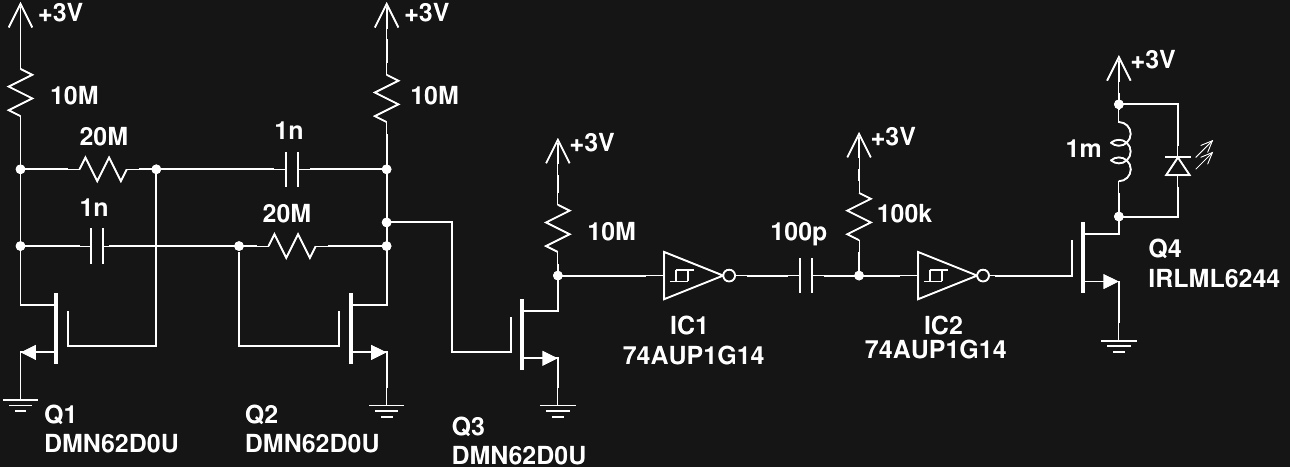
The circuit is a revised version of an earlier attempt I made using a Schmitt-trigger relaxation oscillator. The problem with the original version was an enormous power consumption caused by the ST inverter spending so much time in the linear region. In the new version, I used a MOSFET astable design published by David A. Johnson to drive a one-shot pulse generator I had tried before. The result looks like this:
![]()
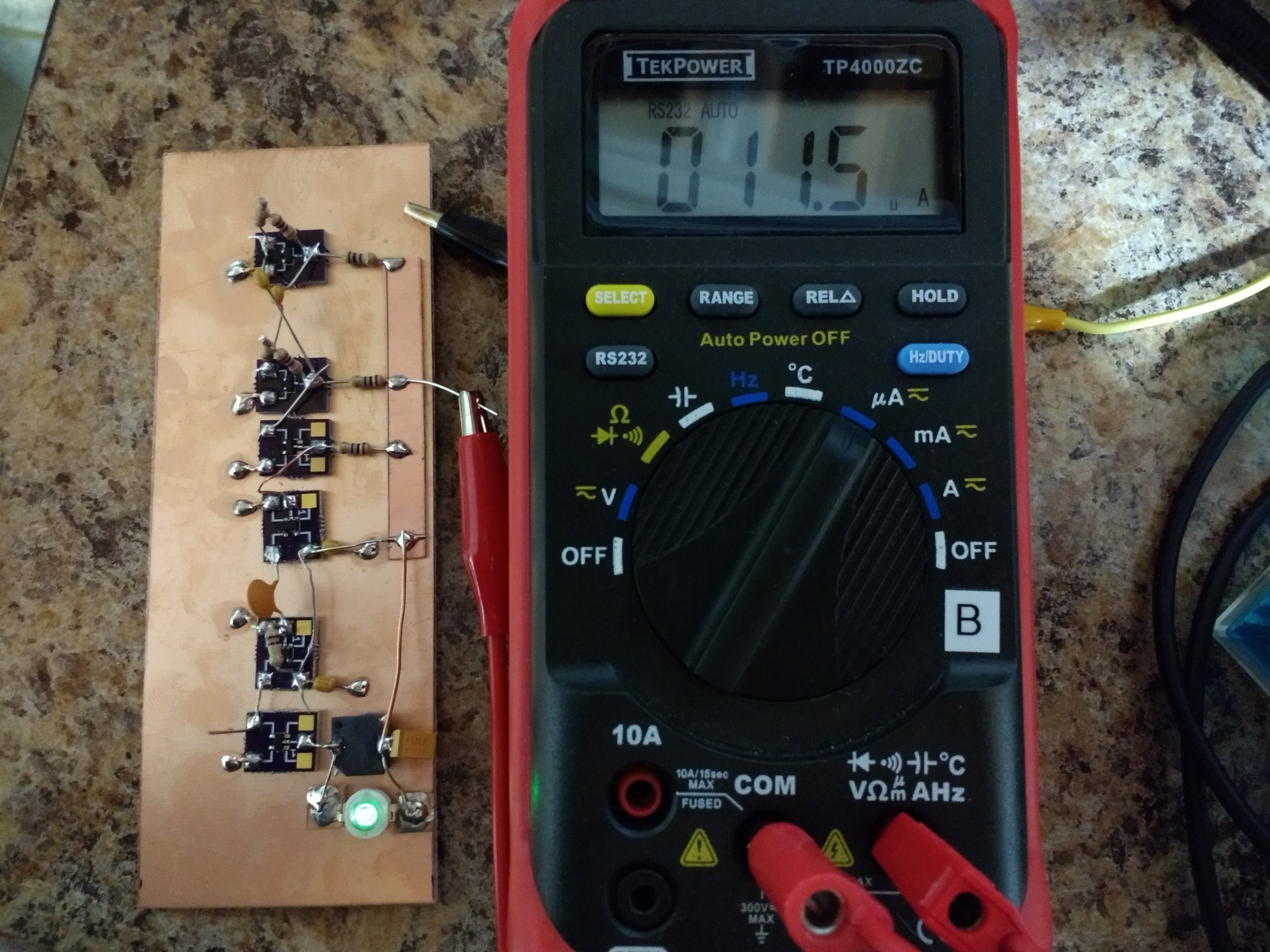
Q1 and Q2 form an astable multivibrator oscillating at about 35 Hz. Q3 is used to square up the output and get a rail-to-rail swing to drive IC1, which in turn creates pulses with very fast edges to drive the IC2 one-shot. The output of IC2 is a pulse of around 12us duration. This ramps up the current in the inductor to a maximum of around 24 mA, which is an efficient drive level for the LED.
The whole circuit draws 11.5 uA, which will run for over 2 years on a CR2032 cell. Without the LED, the circuit consumes around 1.8 uA, so it's at maximum 84% efficient, not counting any losses in the output MOSFET or inductor. At 35 Hz, it's a little flickery, but increasing the frequency seems to increase the overhead current linearly. I think most of the the consumption is actually in IC1 whose input isn't driven very quickly by Q3. For example, I can decrease the current consumption slightly by decreasing the 10M resistor at Q3's drain. This is counter-intuitive, since a lower valued resistor will draw more current, but what's happening is the faster switching speed with the smaller resistor dissipates less power in IC1.
I have yet to try other logic families for the inverters. AUP logic is supposed to be the lowest current, but others might be better with the slow input swings here. I have some 74LVC gates to try next. They're also available in 2-gate packages, which would save a little cost.
There are likely to be issues with this circuit, though. First, the high value resistors and low currents in the astable will be susceptible to leakage on the PCB. To keep things stable, a good wash or two followed by a conformal coat is probably in order.
Another issue is that although the RC time constant for the one-shot can be obtained with 1%-tolerance parts, the pulse length is also a function of the hysteresis in IC2. Unfortunately, this value isn't specified very precisely in the datasheet, so the pulse width could vary considerably from unit-to-unit. I'll have to experiment a bit to see what the variation between parts is, although batch-to-batch variation will probably be larger than that between units from the same wafer.
Overall, I think this is probably a way to create a poorly specified cheap version. It's perfect for the new global economy.
-
V3.1 Release
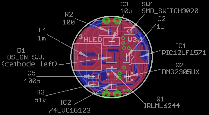
02/02/2018 at 14:35 • 5 commentsThere's not much difference between V3.0 and V3.1 (just an added switch), but I figured I'd give the latest (and final?) version its own page. Here's where all the parts go. Note that it shows an OSLON LED version with a 51k resistor, if you build the Cree XPE2 version, use a 59k resistor (see below).
![]()
Cree XPE2 Green BOM
The PCBs can be ordered from OSH park. Cost is $4.10 for three copies.
Here's a link to a DigiKey cart with all the parts for a single copy using a Cree XPE2 LED. Cost is $6.40, excluding the case, which you have to buy elsewhere. The BOM in table form:
Index Quantity Part Number Description Customer Reference Available Quantity Backorder Quantity Unit Price USD Extended Price USD 1 1 PIC12LF1571-I/SN-ND IC MCU 8BIT 1.75KB FLASH 8SOIC IC1 1 0 0.58 0.58 2 1 296-18758-1-ND IC SNGL MONO MULTIVIBTOR SM8 IC2 1 0 0.7 0.7 3 1 1276-1804-1-ND CAP CER 10UF 25V X7R 1206 C3 1 0 0.26 0.26 4 1 1276-6469-1-ND CAP CER 1UF 25V X7R 0805 C2 1 0 0.1 0.1 5 1 311-100FRCT-ND RES SMD 100 OHM 1% 1/4W 1206 R2 1 0 0.1 0.1 6 1 IRLML6244TRPBFCT-ND MOSFET N-CH 20V 6.3A SOT-23 Q1 1 0 0.54 0.54 7 1 DMG2305UX-13DICT-ND MOSFET P-CH 20V 4.2A SOT23 Q2 1 0 0.44 0.44 8 1 BAT-HLD-001-THM-ND RETAINER BATT CR2025/2032 PC PIN B1 1 0 0.28 0.28 9 1 P189-ND BATTERY LITHIUM 3V COIN 20MM Battery 1 0 0.29 0.29 10 1 XPEBGR-L1-0000-00F02CT-ND LED XLAMP XPE2 GREEN 525NM 2SMD U$1 1 0 1.86 1.86 11 1 311-3599-1-ND CAP CER 100PF 50V NPO 0603 C5 1 0 0.11 0.11 12 1 311-59.0KHRCT-ND RES SMD 59K OHM 1% 1/10W 0603 R3 1 0 0.1 0.1 13 1 CKN10778CT-ND SWITCH TACTILE SPST-NO 0.02A 15V U$2 1 0 0.25 0.25 14 1 SRR6028-102YCT-ND FIXED IND 1MH 150MA 4.5 OHM SMD L1 1 0 0.79 0.79 OSLON Signal Verde BOM
The PCB can be ordered from OSH Park. Cost is $4.10 for three copies.
Here's a link to a DigiKey cart with all the parts for a single copy. Cost is $8.03 (excluding case and PCB).
Index Quantity Part Number Description Customer Reference Available Quantity Backorder Quantity Unit Price USD Extended Price USD 1 1 PIC12LF1571-I/SN-ND IC MCU 8BIT 1.75KB FLASH 8SOIC IC1 1 0 0.58 0.58 2 1 296-18758-1-ND IC SNGL MONO MULTIVIBTOR SM8 IC2 1 0 0.7 0.7 3 1 1276-1804-1-ND CAP CER 10UF 25V X7R 1206 C3 1 0 0.26 0.26 4 1 1276-6469-1-ND CAP CER 1UF 25V X7R 0805 C2 1 0 0.1 0.1 5 1 311-100FRCT-ND RES SMD 100 OHM 1% 1/4W 1206 R2 1 0 0.1 0.1 6 1 IRLML6244TRPBFCT-ND MOSFET N-CH 20V 6.3A SOT-23 Q1 1 0 0.54 0.54 7 1 DMG2305UX-13DICT-ND MOSFET P-CH 20V 4.2A SOT23 Q2 1 0 0.44 0.44 8 1 BAT-HLD-001-THM-ND RETAINER BATT CR2025/2032 PC PIN B1 1 0 0.28 0.28 9 1 P189-ND BATTERY LITHIUM 3V COIN 20MM Battery 1 0 0.29 0.29 10 1 311-3599-1-ND CAP CER 100PF 50V NPO 0603 C5 1 0 0.11 0.11 11 1 CKN10778CT-ND SWITCH TACTILE SPST-NO 0.02A 15V U$2 1 0 0.25 0.25 12 1 SRR6028-102YCT-ND FIXED IND 1MH 150MA 4.5 OHM SMD L1 1 0 0.79 0.79 13 1 475-3450-1-ND LED OSLON SIGNAL GRN 505NM 2SMD 1 0 3.49 3.49 14 1 311-51.0KHRCT-ND RES SMD 51K OHM 1% 1/10W 0603 1 0 0.1 0.1 Design Files
The Eagle design files and a library of all the components used are in the GitHub repo.
-
V3.x Calibration Procedure
01/23/2018 at 04:27 • 5 commentsI added some code in GitHub for calibrating the V3.x boards. Since the inductor has a +/-30% tolerance, the brightness and runtime can vary significantly from board to board. These differences are easily calibrated out by running a little python script I wrote that calculates a calibration table.
![]()
There are just a few steps required to calibrate a newly assembled V3.x board:
1. Run The Calibrator Image
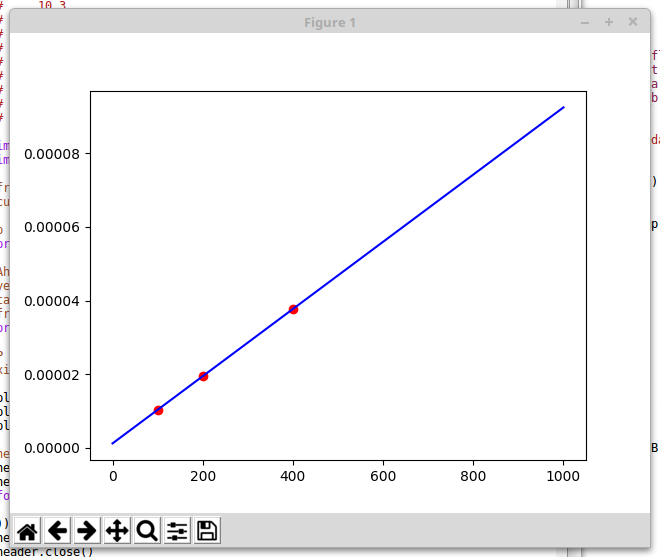
Download the calibrator.hex image. This image runs the LED at three different brightness levels, 16 seconds each. When the image is running, record the currents (in uA) consumed at each brightness. In one recent test run, I recorded the following:
10.3
19.4
37.7
These correspond to hard-coded blink frequencies of 100, 200, and 400 Hz. Save these three current measurements in a file called currents.dat. The C-code source for this image, calibrator.c, is in GitHub.
2. Run the Calibration Script
The python script, calibration.py, reads the currents.dat file you just created, fits a line to current vs frequency, and calculates the frequencies for 1-10 year run times. The script pops up a window with the plot shown above so you can check the calibration. All three points should be on the line. Once you close the plot window, the script generates a header file called modes.h:
#define N_MODES 10
struct run_time period_table[N_MODES] = {
  {1, (int)(31000./262.124721 + 0.5)},
  {2, (int)(31000./124.768381 + 0.5)},
  {3, (int)(31000./78.982934 + 0.5)},
  {4, (int)(31000./56.090211 + 0.5)},
  {5, (int)(31000./42.354577 + 0.5)},
  {6, (int)(31000./33.197487 + 0.5)},
  {7, (int)(31000./26.656709 + 0.5)},
  {8, (int)(31000./21.751126 + 0.5)},
  {9, (int)(31000./17.935672 + 0.5)},
  {10, (int)(31000./14.883309 + 0.5)},
};
3. Compile the Calibrated Hex File
The tritiled_v30_selectable_runtime.c code automatically includes the generated modes.h file, so you just have to recompile to create a calibrated hex file for the board. Once you recompile, program the hex image to the board, and it's done.
If you want, you can verify the current drain for the various modes.
That's it. It shouldn't take more than a few minutes to calibrate your board.
I originally had a script that would do this all automatically, but my PICkit3 has proven to be a little unreliable. I often have to reset it before it will program correctly. It could be that my particular programmer is flaky, some incompatibility with linux, or something else, but it was just too frustrating. The new calibration process is simple, quick, and gives good results, so I'm going to leave it at that.
-
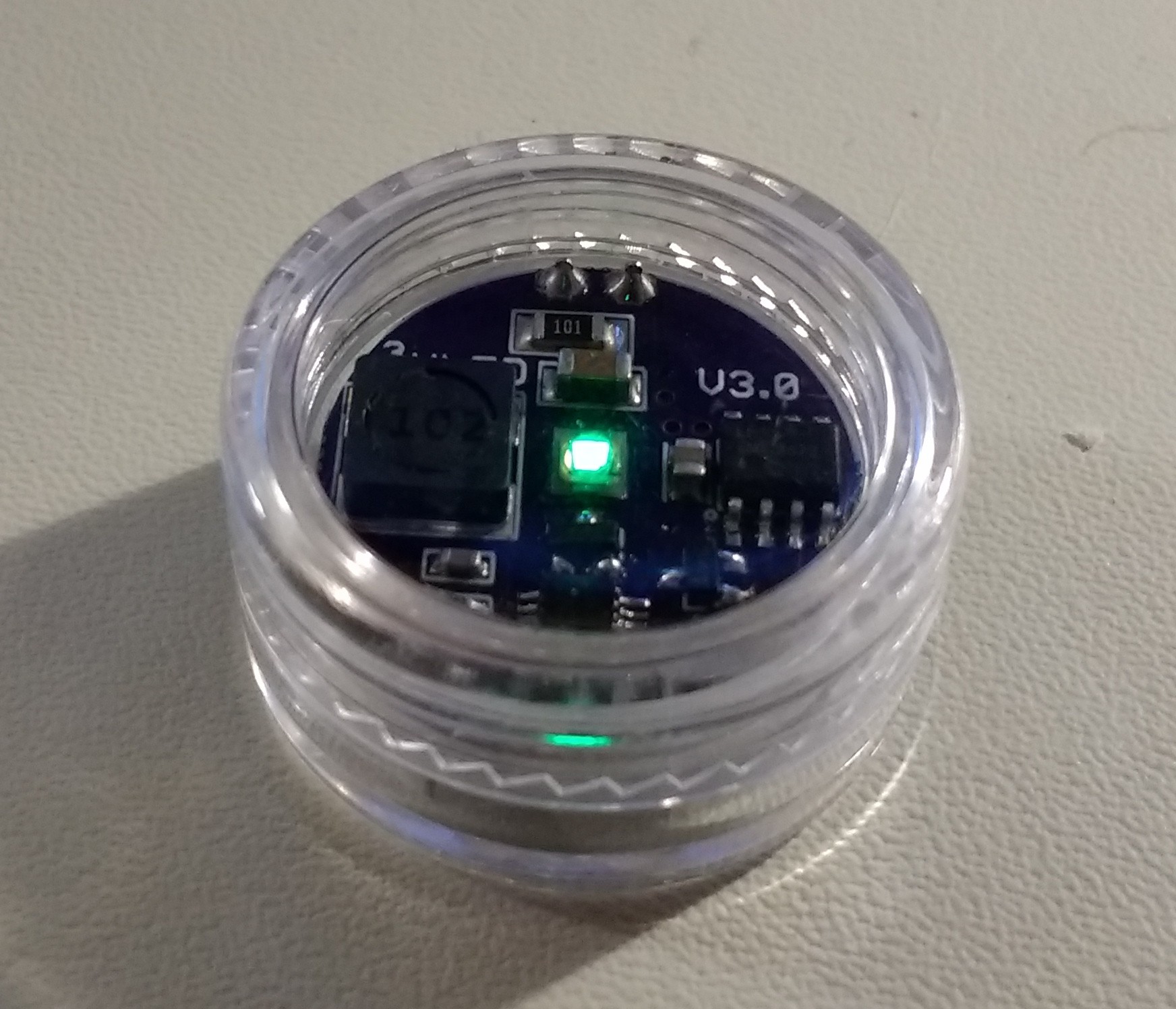
V3.1: Configurable Brightness
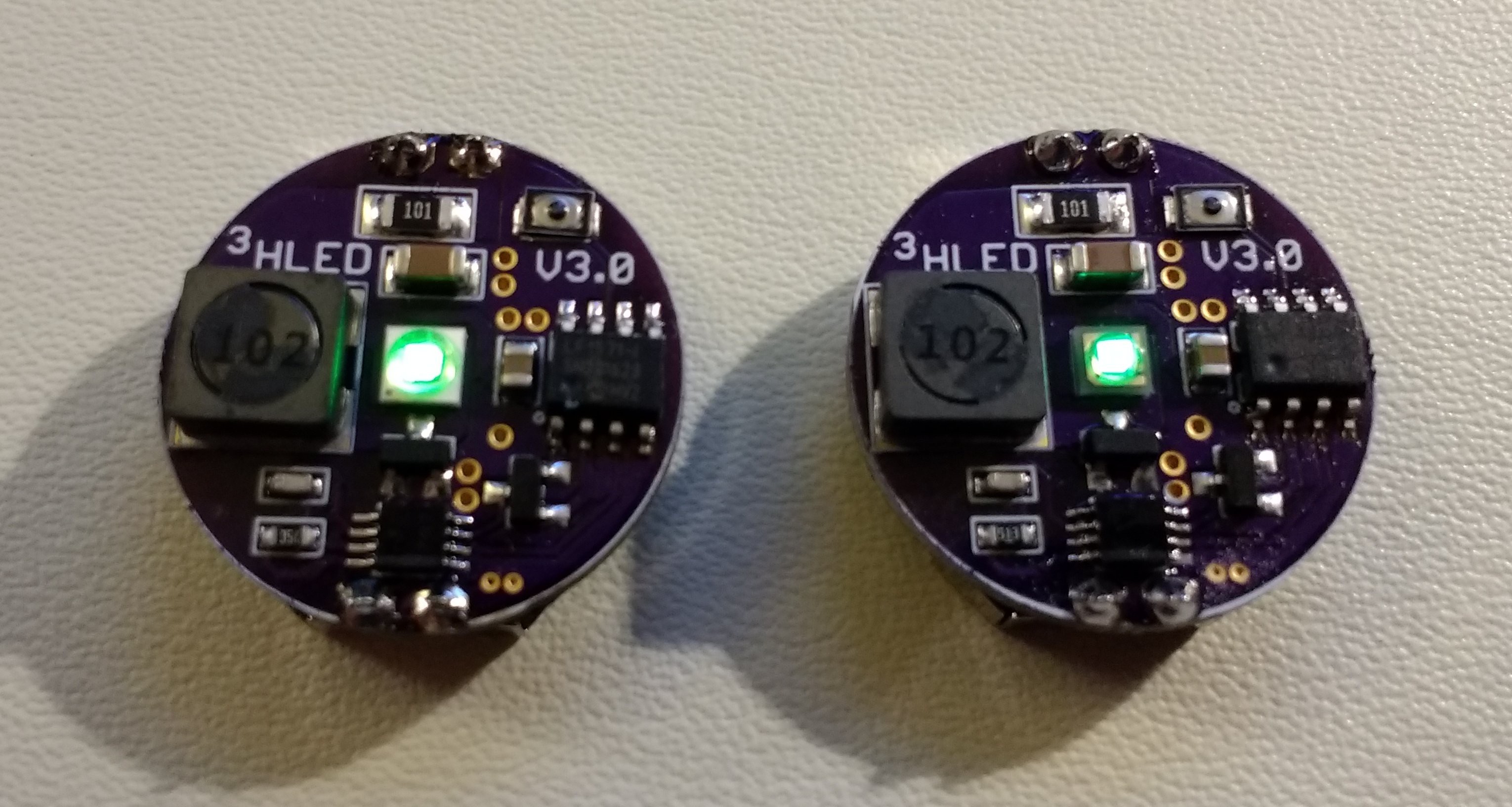
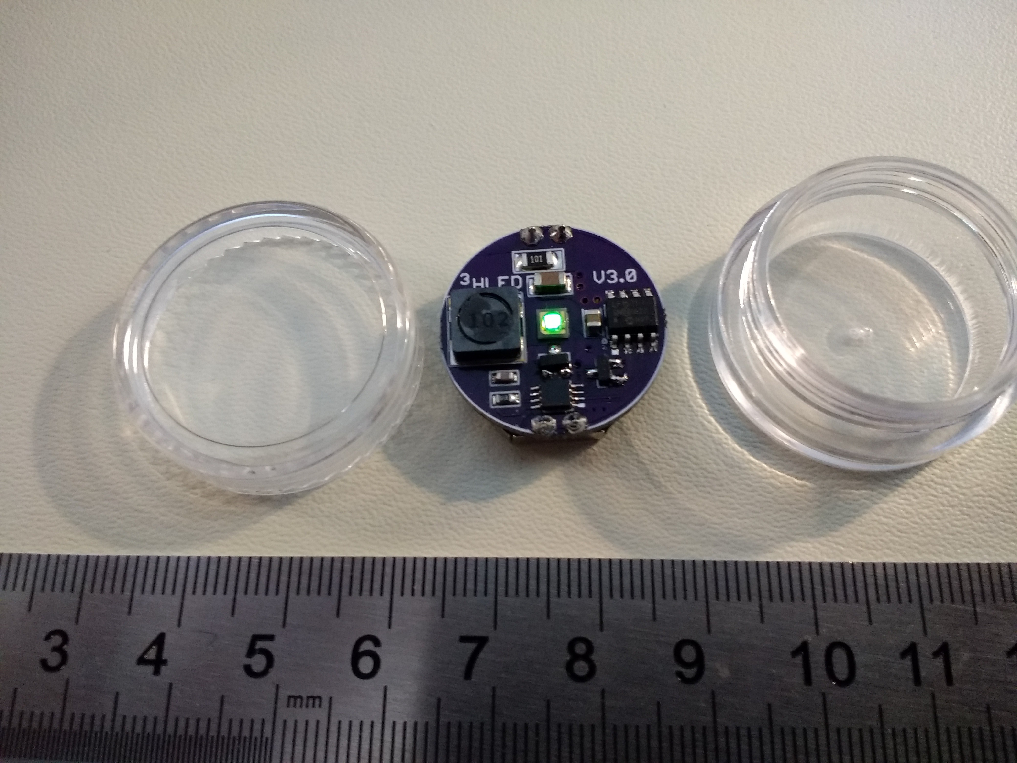
01/18/2018 at 03:10 • 4 commentsI think this is the last version I'm going to make. I added a tiny (3x2mm) switch to the V3 board to allow you to select the brightness/run-time at startup. You can see the switch in the upper right, just above the incorrect "V3.0" silkscreen text (I fixed this since these boards were made). It basically fits in a 1206 footprint! The Cree XPE2 is on the left, with the OSLON Signal Verde LED on the right. I didn't make a V3.1 PCB for the Luxeon C LED. The Eagle files and gerbers are in GitHub.
![]()
The switch was added to go with the new C-code. The code allows you to tune the brightness when you first insert the battery. Pressing the switch cycles between 1-10 year burn rates. You get a preview of the brightness for 4 seconds, then the LED blinks out the run-time in years (e.g. four blinks = four years). Once you let it cycle uninterrupted three times, the brightness gets locked in until the battery is removed.
The code also has some additional enhancements (some are enforced in the makefile). Most importantly, the code fits into the lower half of flash memory, which is write-protected in the configuration bits. This prevents accidental over-write of the code by an errant program. The code has to write to program flash memory to store the brightness mode, since there is no EEPROM on this part. To make things safer, the brightness mode is stored in the upper half of flash (read/write), with the code itself safely in the lower half. Microchip probably could have provided a finer granularity on their write-protection (all/none/half), but the part is what it is.
BOM
The V3.1 is identical to the V3.0 except for the switch. This particular switch is available in three different activation forces (100g, 160g, 240g). I have samples of the 160g and 240g, and am not sure which I like best. They both seem to work OK:
(160g) KXT 321 LHS switch, DigiKey part #CKN10778CT-ND, $0.25 each
or
(240g) KXT 331 LHS switch, DigiKey part #CKN10779CT-ND, $0.25 each
Next Up
I'm still tweaking the automatic brightness tuning script. I'll be posting that soon.
I'm also going to run a head-to-head experiment to answer the question: "why don't you just use an LED and resistor".
-
Stupid Case Tricks
01/08/2018 at 19:36 • 2 commentsHere's a quick rundown on what I have learned from playing with the case:
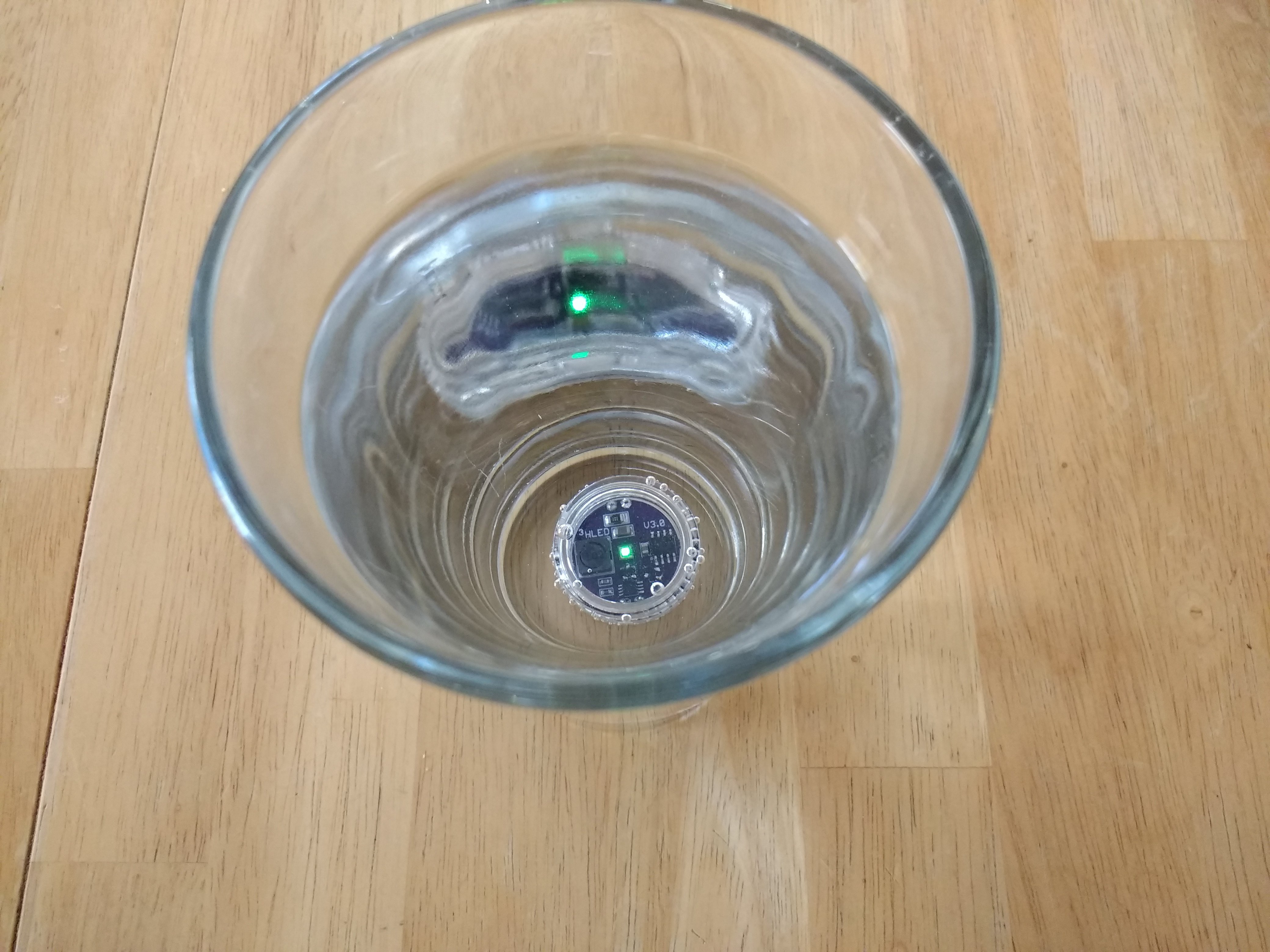
TritiLEDs Sink
![]()
I had hoped they would float, but I guess that would make the case larger. This one stayed under water for a day with no leakage. It was sealed with a 25x1mm o-ring. The fit isn't very good, though, and I'm going to try to find some better ones.
Spare Battery
You can fit a spare battery in the bottom of the case:
![]()
The "5g" jars are a little too deep, and there's just enough space for a spare CR2032. For 10-year run-times, a spare cell probably isn't too interesting, but for a bright 1- or 2-year marker, having a spare cell right in the case could be handy.
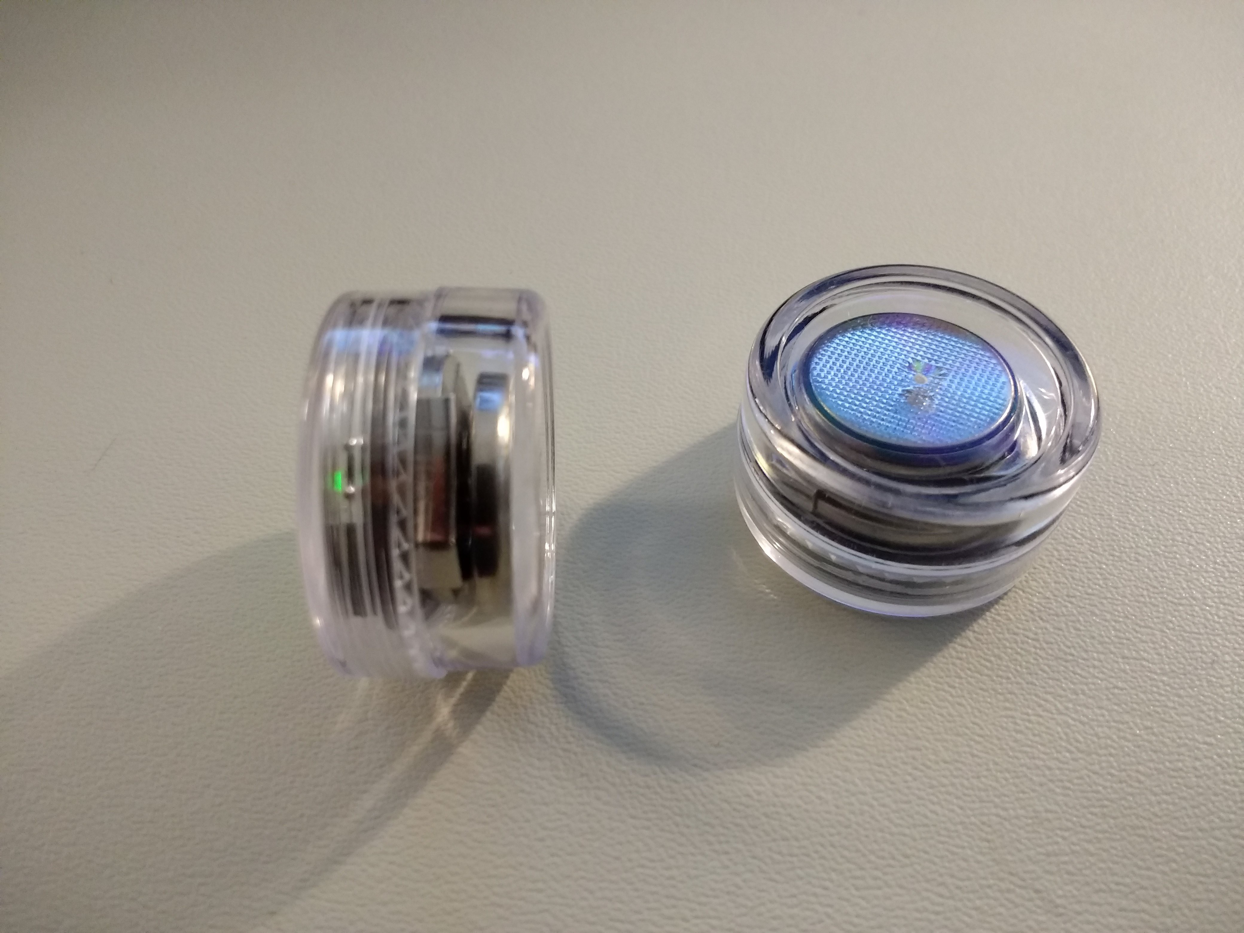
Magnets!
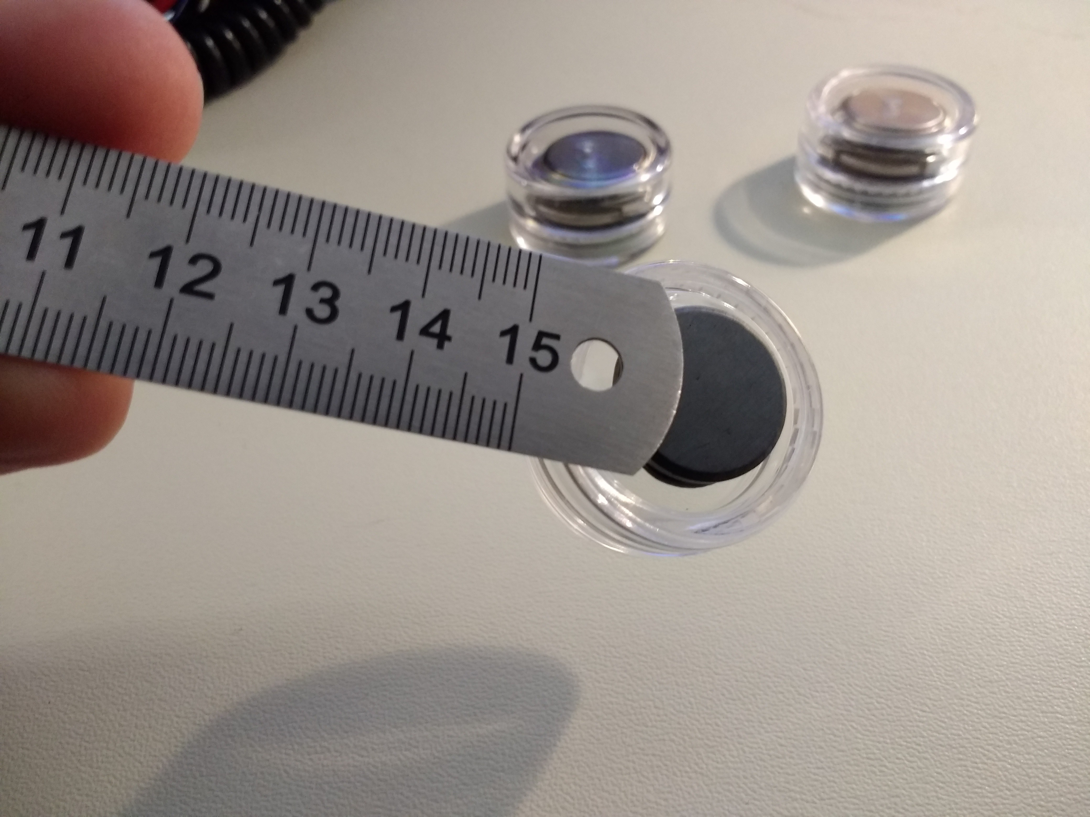
Like lasers, magnets make everything more interesting. Here, I glued a cheap 18mm ceramic magnet to the bottom of a case with a dab of epoxy:
![]()
The ceramic magnet isn't very strong, but holds the light OK. A strong neodymium magnet will hold it without glue, just from being attracted to the coin cell through the case. The best solution is probably glue+neodymium, but then you might have trouble extracting the PCB to replace the battery.
-
Determining maximum runtime: 17.6 to 20.2 years (CR2032)
01/06/2018 at 21:34 • 25 commentsOK, so for the coin cell contest, we want to know the maximum runtime. I have considered estimating this three different ways. As an example, I'll take the minimum pulse rate of the V3.0, 0.5 Hz (the light blinks once every 2 seconds). I measured the current drain to be around 1.15uA at this rate.
How long will this run on a CR2032?
First, you need to decide on the cell's capacity. I'll use 225mAh, which is on the Panasonic CR2032 Datasheet, since I'm using Panasonic cells. Other manufacturers quote other numbers.
Capacity / current
In this method, which you see most commonly used, you divide the capacity of the cell (in Ah) by the current drain of the device (in A), to yield a lifetime in hours. To get years, we divide by 24 hours/day, and 365 days/year (if you want to get technical, you can use 365.25). In this case, we get:
0.225 / 1.15e-6 / 24 / 365 = 22.3 years
Nice, but this exceeds the "shelf life" quoted as 10 years.
WTF is shelf life, anyway? It certainly doesn't mean the battery is dead at that point if left on the shelf. Instead, it's a measure of self-discharge. Elsewhere in their Lithium Handbook, Panasonic quotes a 1% self discharge rate per year. So, at the end of the 10 year shelf life, the cell should retain more than 90% of its initial capacity (depending on 1% of what: see below). Considering this, the 22.3 years calculated above doesn't seem correct anymore - at that point, the battery would have lost some of its initial capacity sitting on a shelf. It would be nice to take this into account.
Considering Self-Discharge
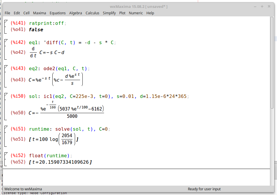
To include the effects of self-discharge, I first assume the 1% per year means 1% of the remaining capacity. This means the capacity obeys the differential equation:
where s is the self-discharge rate, in this case 0.01/year. The solution of this equation is an exponential decay describing the capacity of a battery on the proverbial shelf, which is interesting, but doesn't answer the question. To figure the runtime, we also need to include the circuit's current drain. For the moment, assume the drain is a constant current of d amps. The equation now looks like:
In 2018, there's no need to be intimidated by (simple) differential equations like this: just throw them into Maxima.
![]()
I got maxima to solve the ODE, selected a specific solution by giving the initial conditions (fresh battery at t=0), and finally solved the result for the time when C=0. The result: 20.2 years. Two years shorter than the earlier estimate. (Note: earlier, I posted 19.4 years here due to a typo in the maxima code).
Linear Self-Discharge
It's also possible that 1% discharge per year means 1% of the initial capacity per year. This would mean a linear decay of capacity obeying:
The solution to this one is trivial: we just add (0.225 Ah * 0.01 / 365 / 24) = 257nA to the device current. For the lifetime, we get 0.225 / (1.2e-6 + 257e-9) / 24 / 365 = 17.6 years. Two and a half years shorter still.
So, there you have it: the TritiLED V3.0 can run for somewhere between 17.6 and 20.2 years on a CR2032.
There's a subtle problem with each of these estimates. When the cell voltage falls over time, the circuit current also falls. This would extend the run-times, since the current is continually dropping. Ignoring this effect would tend to under-estimate the run-time, so the above estimates may be slightly conservative.
-
Selecting brightness/battery life at runtime
01/06/2018 at 19:16 • 2 commentsThe simple assembly code I wrote to get V3.0 up and running works fine. You can configure the brightness in code, then download a new image to the PIC to change the battery lifetime. This is OK if you are building these devices for your own use, but inconvenient for people who just want to buy them. So, it would be nice to have a simple user interface on the board to select the runtime.
I was initially concerned that the runtime might get accidentally changed over the years, then @jaromir.sukuba suggested a configuration mode that was only accessible briefly after the battery was inserted. After that period, the brightness (and battery life) are locked-in until you remove the battery.
I wrote some C code that does this yesterday - you can see it in the GitHub repo. Well, it's mostly C-code. There are two helper functions I had to write in assembly to access the high-endurance flash (HEF) portion of program memory to store the current mode setting.
The user interface is simple. After inserting the battery, the LED blinks out the runtime in years: 5 blinks = 5 years, etc. To increment the runtime, you short pin 4 to pin 8 (RA3 to GND). This "switch" is properly debounced in software. I found some 2.6x1.6 mm switches, and I think I'm going to spin a set of V3.1 boards with them. The code blinks out the runtime 10 times, then enters the running mode, and can't be re-configured without removing the battery.
The only downside to this approach is that you sometimes have to wait a long time for the capacitors to discharge. At 10-year run-times (or more), the mere 11uF of capacitance on board can power the LED for many seconds!
There are a few configurable parameters in the code controlling the interface:
// number of cyles of blinks to show before exiting config mode
#define N_CYCLES 10

// number of pulses per "blink" in config mode, higher = brighter blinks
#define N_PULSES 10

// year run-times and corresponding PWM periods
#define N_MODES 10
struct run_time
{
  uint8_t years;       // number of years of run-time or mode number
  uint16_t pwm_period; // PWM period (in units of 1/31000 s)
};

// Note: frequencies converted to pwm periods
const struct run_time period_table[N_MODES] =
  {{1, (int)(31000./326. + 0.5)},
   {2, (int)(31000./155. + 0.5)},
   {3, (int)(31000./98. + 0.5)},
   {4, (int)(31000./69. + 0.5)},
   {5, (int)(31000./52. + 0.5)},
   {6, (int)(31000./41. + 0.5)},
   {7, (int)(31000./33. + 0.5)},
   {8, (int)(31000./27. + 0.5)},
   {9, (int)(31000./22. + 0.5)},
   {10, (int)(31000./15. + 0.5)}
  };

// default mode index
#define DEFAULT_MODE_IDX 1
The run-times and associated PWM frequencies are stored in a table in the flash. In this case, you can select from 1 to 10 year lifetime in 1-year increments. These values can be manually determined, or you can use a script and some hardware to find them automatically (I'll be publishing this script soon, I'm just cleaning it up now). The table shown here is not quite right: there is no need for the frequencies to be integers. Frequencies with greater precision (e.g. 21.7 vs 22), will result in more accurate PWM period counts (e.g. 1428 vs 1409). The differences can be significant for multi-year run times.
I guess I just promised at least two more logs: the auto-tuning script, and V3.1 PCBs with a tiny switch. It might feel like work if I didn't love it :-)
-
V3.0 Release
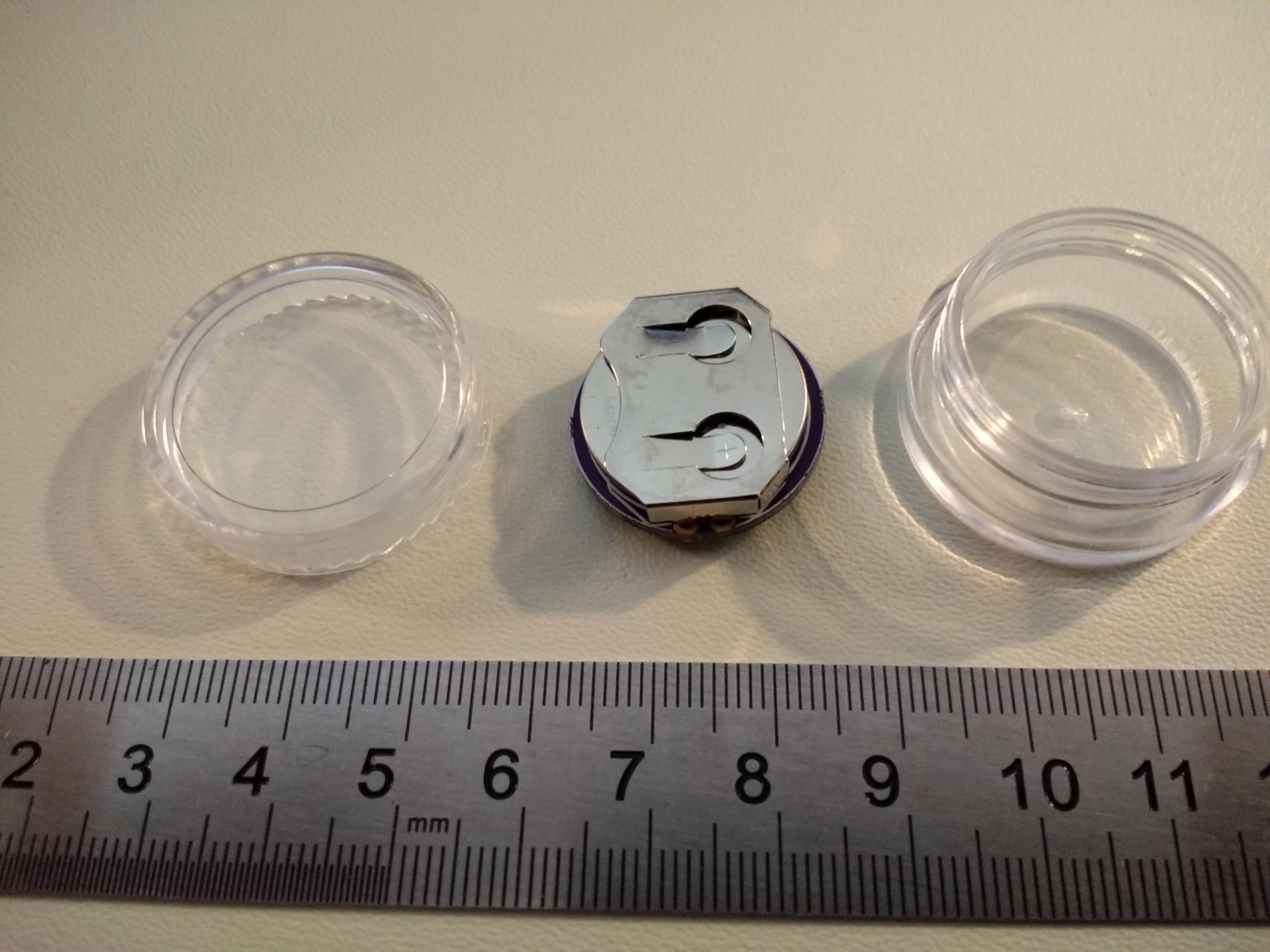
01/03/2018 at 15:02 • 1 commentI've finished the design and tuning for the OSLON Signal Verde LED flavor of V3.0. The design is documented here; as I tune the other LED flavors, I'll add to this log. Key features of V3.0 are the ability to finely tune the brightness/lifetime trade-off, build-time configuration for different optimal LED drive currents, and using a "5g" plastic jar as a case.
![]() The PCB uses a through-hole CR2032 holder (smaller than the SMT version), allowing it to fit in the jar.
The PCB uses a through-hole CR2032 holder (smaller than the SMT version), allowing it to fit in the jar.![]()
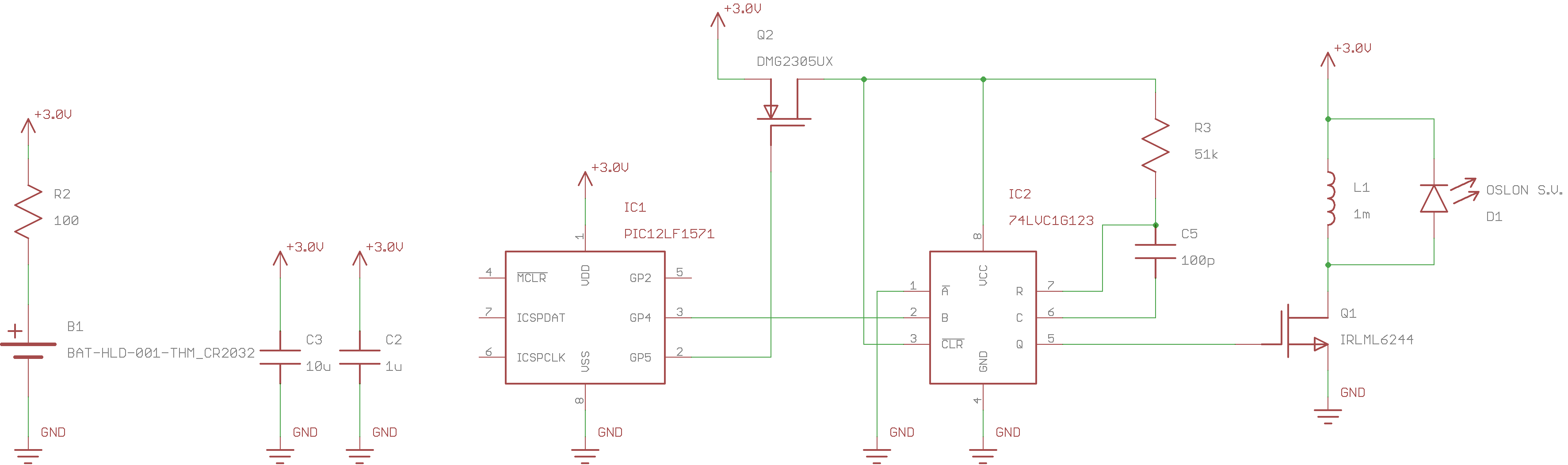
Circuit
![]()
The V3.0 circuit uses a 74LVC1G123 monostable to produce short, accurate pulses for ramping up current through the inductor. The inductor size and monostable pulse width are selected to optimize the drive current to the LED, based on measured LED efficiency vs current. A PIC12LF1571 uses two synchronized PWM outputs to control the pulses. One PWM gates power to the monostable (it consumes too much quiescent power), while the second PWM triggers the pulse. The 16-bit PWMs on the PIC allow very fine tuning of pulse frequency and hence battery lifetime vs LED brightness. Combined with inductor and monostable resistor selection, the circuit lets you tune for very good electrical and LED efficiency while allowing accurately tunable runtime.
Note: a different value of R3 is required for each type of LED.
Bill of Materials
The following components are required for any flavor of V3.0:
- (1) PIC12LF1571 8-SOIC DigiKey part # PIC12LF1571-I/SN-ND $0.58 each
- (1) 74LVC1G123 monostable SM8. DigiKey part # 296-18758-1-ND $0.70 each
- (1) 10uF 25V 1206 X7R MLCC capacitor. DigiKey part # 1276-1804-1-ND $0.26 each
- (1) 1uF 25V 0805 X7R MLCC capacitor. DigiKey part # 1276-6469-1-ND $0.10 each
- (1) 100 ohm 1206 resistor. DigiKey part # 311-100FRCT-ND $0.10 each
- (1) IRLML6244 N-channel SOT23 MOSFET. DigiKey part # IRLML6244TRPBFCT-ND $0.54 each
- (1) DMG2305UX P-channel SOT23 MOSFET. DigiKey part # DMG2305UX-13DICT-ND $0.44 each
- (1) CR2032 Battery retainer. Digikey part # BAT-HLD-001-THM-ND $0.28 each
- (1) 100pf C0G 0603 capacitor. DigiKey part # 311-3599-1-ND $0.11 each
- (1) "5g" polystyrene jar. Buy from Amazon $7.99/50, ebay or elsewhere
- (1) CR2032 cell. DigiKey part # P189-ND $0.29 each
Depending on the LED you choose, you will need a different PCB, resistor, and possibly inductor. Choose from one of the LEDs in the following sections:
OSLON Signal Verde (505nm)
This LED has the best optical match to dark-adapted eyes. If you are just going to build one version, use this LED, and forget about the $3.49 price tag. It requires a 1mH inductor and 51k resistor for optimum efficiency.
- (1) OSLON Signal Verde (505nm) LED. DigiKey part # 475-3450-1-ND $3.49 each
- (1) Bourns SRR6028-102Y 1mH inductor DigiKey part # SRR6028-102YCT-ND $0.74 each
- (1) 51k 0603 1% resistor. DigiKey part # 311-51.0KHRCT-ND $0.10 each
- (1) PCB. Order from OSH Park. $4.10 for 3.
Luxeon C Cyan
This LED is my second choice for dark-adapted eyes. It's cheaper than the OSLON at $2.74, but just a little too blue for optimum visibility. The higher optimal current also makes it flash more visibly at extended run-times (see below).
- (1) Luxeon C Cyan LED. DigiKey part # 1416-1917-1-ND. $2.74 each.
- (1) Bourns SRR6028-102Y 1mH inductor DigiKey part # SRR6028-102YCT-ND $0.74 each
- (1) 75k 0603 1% resistor. DigiKey part # 311-75.0KHRCT-ND $0.10 each
- (1) PCB. Order from OSH Park. $4.10 for 3.
Especially with this LED, you may want to choose a different inductor/resistor combination if you want extended run-times with minimal flickering. See the section on alternate inductors below.
Cree XPE2 Green
This is an economical alternative to the above LEDs. The 525nm emission wavelength is a good trade-off for medium light viewing conditions, being in-between the 507nm and 555nm sensitivity peaks of the human eye. It's a bargain, too: even opting for the brightest bin available at DigiKey, you'll only pay $1.86.
- (1) Cree XPE2 Green (525nm) LED. DigiKey part #XPEBGR-L1-0000-00F02CT-ND. $1.86 each
- (1) Bourns SRR6028-102Y 1mH inductor DigiKey part # SRR6028-102YCT-ND $0.74 each
- (1) 59k 0603 1% resistor. DigiKey part # 311-59.0KHRCT-ND $0.10 each
- (1) PCB. Order from OSH Park. $4.10 for 3.
If you're ordering parts, get the 59k resistor. If you only have a stock of E24 series resistors, you can substitute a 56k or 62k.
Be careful mounting this LED. I had to do some skillet-rework on my first one. The mark is on the anode side, unlike any other diode ever created. I realize the good people at Cree are special snowflakes who should get to do it any way they like, but they should put the f'ing mark on the cathode like everyone else.
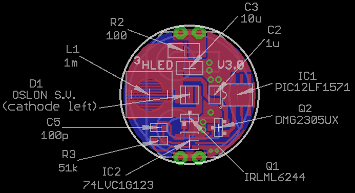
Assembly Instructions
None of the LED choices can be hand-soldered, so you'll have to reflow the board. All of the components except the through-hole battery holder can be mounted on the top, then the holder hand-soldered. Consult the parts placement diagram below.
![]()
Pay special attention to the MOSFETs - I mixed them up on my first board, and had to swap them with a soldering iron. The other likely sources of confusion are mixing up the 0603 R's and C's (I had to check twice), and mis-orienting the LED (cathode goes left). Also note that there is a different value of R3 for each LED.
Software
Fixed-runtime Assembly Code
This version uses a hard-coded pulse frequency, so the brightness and battery life are fixed when you download the code. The assembly source for the code is in the GitHub repo. I also checked in a hex file, but it's probably not very useful. Due to component tolerances, each PCB requires tuning to achieve a specified battery lifetime (you didn't have this option with earlier versions). There is a single parameter in the code controlling the brightness/lifetime trade-off:
;;;
;;; adjustable pulse frequency parameter
;;;
FREQ            equ .157
The FREQ parameter controls the LED pulse frequency. In the case of the first OSLON Signal PCB, I found that a frequency of 157 Hz produced a current drain of 12.5uA, equivalent to a 2-year run-time for a CR2032.
The plots in the next section "Tuning Parameters" should be used to get initial estimates of the pulse frequencies required to achieve a specified run-time. After that, some trial-and-error tuning is required.
I'm working on an automatic tuning script that uses a PICkit3 and serial-enabled DMM to measure the current drain and determine the correct frequency for a given run-time.
Programmable-runtime C-Code
This version allows you to set the runtime when you first insert the CR2032. The runtime is adjustable from 1 year to 10 years: the LED blinks out the runtime in years (5 blinks = 5 years, etc). After blinking out the runtime 10 times, the code enters the normal glow mode, and the brightness/current consumption is fixed until you remove the battery. The code is documented in a separate log, and is available in the GitHub repo.
For the V3.0 PCB, you need to short pins 4 and 8 on the PIC12LF1571 to change the runtime. A V3.1 PCB will include a tiny switch for this purpose.
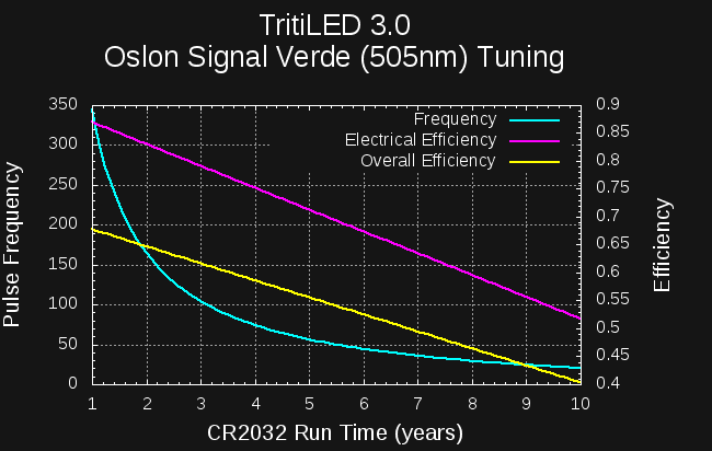
Tuning Parameters
The following plot is an estimate of the pulse frequency required to achieve various run-times from a CR2032 for the OSLON Signal Verde LED.
![]()
These numbers are estimated based on simulations, but seem fairly close - certainly good enough to begin fine-tuning. For example, I determined a frequency of 157 Hz on the first board for a 2-year run-time (12.5uA), which agrees with the plot quite well. Also shown on the plot are the electrical efficiency (magenta) and "overall" efficiency. The latter is a combination of the electrical efficiency and how well the circuit matches the optimum LED drive current. In both cases, you can see how the efficiency drops as run-time is increased. This is due to a fixed overhead for running the PIC PWMs. You can also see that for long run-times, the pulse frequency becomes low enough to flicker visibly. At 10-years, this LED is pulsing at 20Hz, which is quite visible. If you arbitrarily take 50Hz as the flicker threshold, you can set this version to run as long as 5.5 years with no flickering.
Here's the same plot for the Cree XPE2 525nm LED:
![]()
I haven't verified this curve with the PCB yet - I'll delete this sentence when I do.
This LED requires a slightly higher current for best efficiency, so there is more energy per pulse. The net result is a lower pulse frequency for a given current drain. So, this LED will begin to flash visibly at shorter lifetimes than the OSLON LED. The difference isn't huge, though. At a 10 year life, this LED is flashing at 15Hz, still very visible, but not that much different from the OSLON. Again using an arbitrary 50Hz flicker threshold, this version can be set to a maximum 4.5 year run-time before flicker becomes visible.
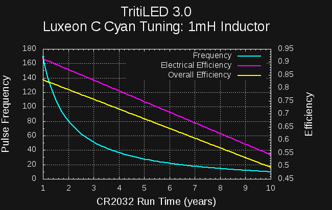
The Luxeon C LED is a little different. The efficiency peak for this LED is at a higher current, meaning longer pulse times or smaller inductors for best efficiency. Here's the chart using a 1mH inductor (and 75k resistor):
![]()
The efficiency is very good, but due to the higher energy-per-pulse, you need to use low frequencies to get extended run-times. For example, using the 50Hz criteria, you can only extend run-time to about 3 years before the LEDs flickering becomes noticeable.
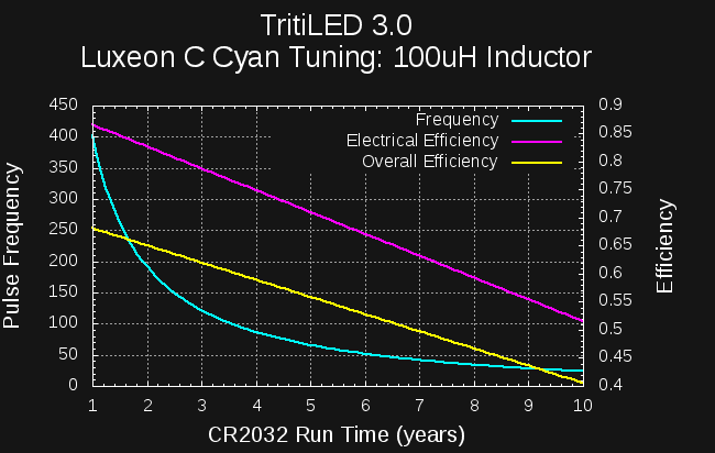
If, on the other hand, you use a smaller 100uH inductor (and 15k resistor), you get the following:
![]()
Now, each pulse is much shorter (1.9us), so dumps less energy into the LED, and the frequency for a given run-time is higher. You can extend the run time to 6 years before hitting the 50Hz threshold. The penalty is reduced overall efficiency (compare the two yellow lines), since the LED isn't driven as close to its optimal current.
Alternate Inductors
There is a trade-off between efficiency and flickering at extended run-times for this circuit. Smaller inductors produce pulses of less energy, so a higher frequency can be used at a given current drain. Unfortunately, as the inductor is reduced, the overhead of the rest of the circuit is larger in comparison, which reduces the overall efficiency. I've prepared the following tables for those who might want to make extended-run-time versions with minimal flicker, and are willing to sacrifice some efficiency to do so. In each table, the recommended values are in bold.
The tables list the inductor (L1) value, the resistor (R3) value, the runtime at which the pulse frequency drops below 50Hz, and a figure-of-merit efficiency relative to the best you could possibly do from coin cell to light with the given LED. The figure-of-merit is calculated for a 2-year run-time.
Note that figure-of-merit efficiencies in the tables are relative: you can't make comparisons directly between the different LEDs, since I don't have a calibrated way to measure the light output.
OSLON Signal Verde (505nm)
Inductor R3 50Hz Threshold (yrs) 2yr FOM 100uH 13k 7.7 50% 220uH 20k 6.8 55% 470uH 33k 6.2 60% 680uH 39k 5.9 62% 1mH 51k 5.5 65% Luxeon C Cyan
Inductor R3 50Hz Threshold (yrs) 2yr FOM 100uH 15k 6.2 65% 220uH 24k 5.2 71% 470uH 43k 4.0 75% 680uH 56k 3.6 77% 1mH 75k 3.0 79% Cree XPE2 Green (525nm)
Inductor R3 50Hz Threshold (yrs) 2yr FOM 100uH 12k 7.6 56% 220uH 20k 6.5 62% 470uH 36k 5.4 68% 680uH 47k 4.9 70% 1mH 59k 4.4 73% TBD
I will continue to update this log as I build and tune various flavors of V3.0. If you find anything confusing, missing, or suspect an error, please let me know.
-
First V3.0 PCB
01/03/2018 at 03:44 • 5 commentsI populated the first V3.0 PCB today. It's actually been through a few iterations, but I didn't even bother filling any of the earlier boards. This one is finally worth building. The board is smaller now (23mm diameter), so it fits inside cheap, widely available "5g" polystyrene jars, but still uses an inexpensive replaceable CR2032 for power.
![]()
This first PCB uses an OSLON Signal Verde LED. I tuned this particular PCB to a 2-year run-time (12.5 uA) on a CR2032, and it blinks at 157 Hz. The breadboarded version needed to be tuned to 123Hz to achieve the same run time (probably due to the 30% inductor tolerance). The ability to fine-tune the current draw was one of the design goals of the V3 (as was fitting inside these jars).
I also have PCBs for Luxeon C and Cree XPE / Cree XPE2 LEDs. They are identical to this one except for the LED pads.
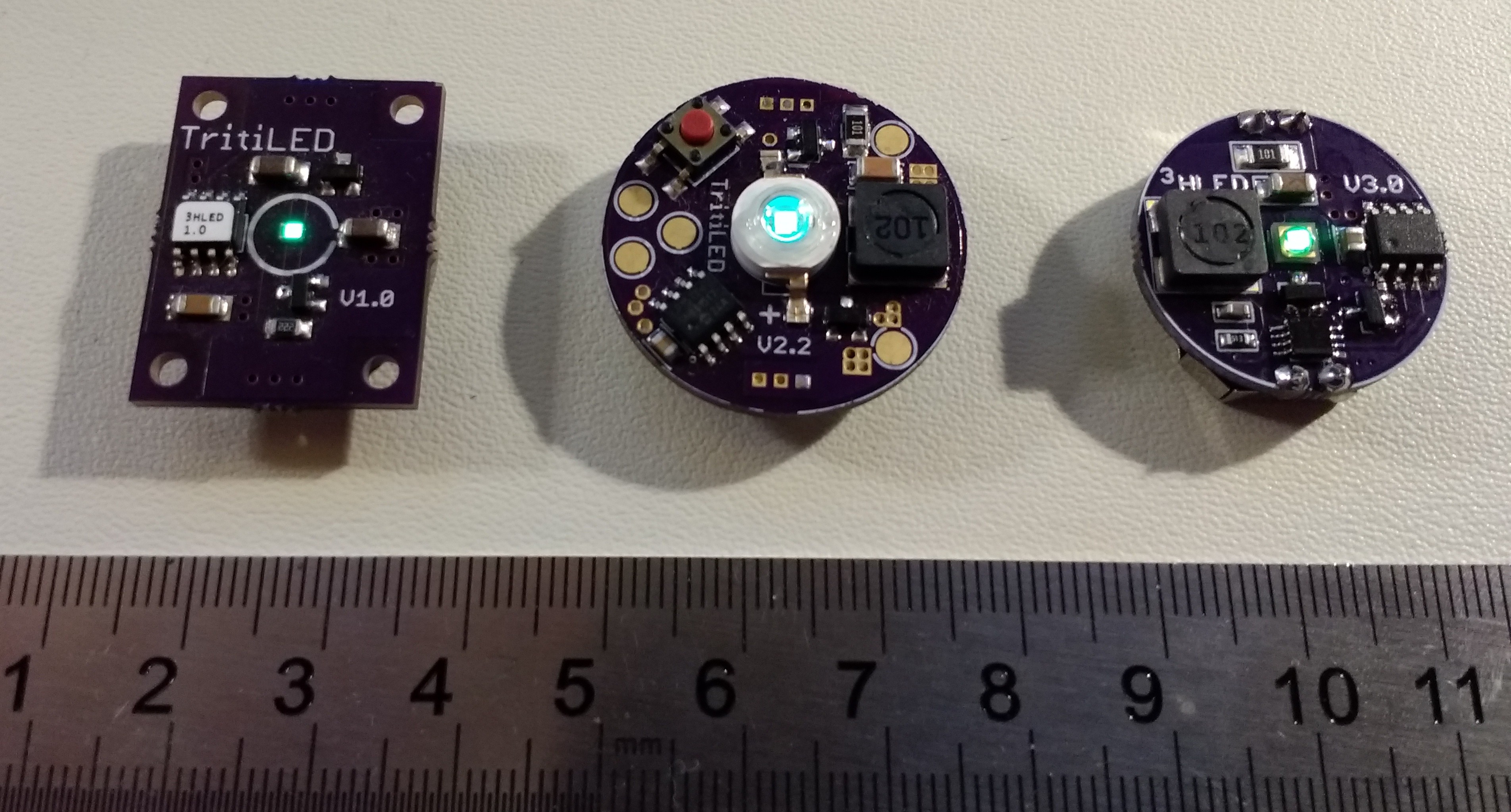
Here's a visual comparison with the previous two generations for reference:
![]()
One of the key differences is the use of a through-hole CR2032 holder, which is actually smaller in diameter than the surface-mount version (since the through hole doesn't need flat mounting tabs). This was the final change required to fit the PCB inside the jar.
Tuned to the same 2-year run time as the V2.0, the V3.0 is noticeably brighter. It's roughly as bright as the V1.0 (which only runs 1 year). But, you can tune the V3.0's brightness to last from less than 1 to more than 10 years on a CR2032 cell.
I'll put together a more detailed post for those wanting to build some of this new version, including a BOM and placement diagram. The PCB designs are already in GitHub, I just need to polish the software a little and put it up there.
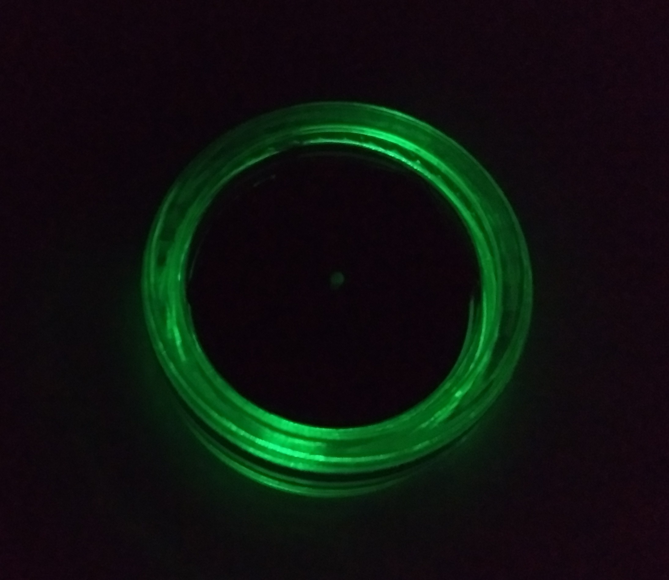
EDIT: I discovered that the clear jar makes a nice dim ring of light when placed upside down. I usually keep a few of these lights on my nightstand, but the light can actually be enough to bother me. Being able to attenuate the output somewhat by turning them upside down is an added bonus, especially since it looks so cool.
![]()
-
Programming PICs with Python
12/31/2017 at 04:09 • 8 commentsNo, not *in* python; they're still coded in assembly. I mean using python to drive the assembler and PICkit3 programmer. It turns out that MPLABX tools have a decent command-line interface. I wrote some simple python classes to take the pain out of the command-line switches and enable automatic tuning of V3.x TritiLEDs.
One of the problems with the V2.x design was the inability to fine-tune performance for variations due to part tolerances (the inductor, for example is +/-30%). Since the pulse frequency of the V3.x design can be very accurately tuned, I would like to be able to "tune out" the component tolerances once the devices are assembled. This calibration process means programming the part, measuring the current drain, adjusting the pulse frequency, recompiling, and re-programming. Then, maybe looping through the whole process a few times. This is not something I want to do manually for each unit.
So, that's where the python comes in. The fundamental code is shown below.
Scripting the MPASMX assembler is trivial. In order to tune the frequency parameter, I simply write a one-line include file from python including an "equ" directive. This file is included by the main assembly file.
Scripting the PICkit3 programmer is much more interesting. You control the programmer through a script called "ipecmd.sh" (check for the name on different OS's), and it's documented in a file called "Readme for IPECMD.htm" in the mplabx/docs directory The programmer has provisions for powering the target device directly, and allows you to adjust the Vdd voltage. Coupling this with a serial-enabled DMM makes a very nice little test kit: you can program different code on the device, then measure the current drain over a range of supply voltages. There are probably a lot of interesting uses.
I still have to integrate the DMM code and write the iterative tuning algorithm, but that's probably of less general interest than programatically driving the PICkit3.
One thing I've discovered so far is that the output voltage of the PICkit3 doesn't seem very accurate. I may add another serial-DMM to the test setup to measure the actual voltage instead of relying on what I tell the programmer to supply.
#!/usr/bin/env python

import subprocess

mplabx_path = '/opt/microchip/mplabx/'

class MPASM:
  def __init__(self, path):
    self.path = path + 'mpasmx/mpasmx'
  def assemble(self, filename):
    subprocess.call([self.path,
                     filename])


class PICKIT3:
  def __init__(self, path, part):
    self.path = path + '/mplab_ipe/ipecmd.sh'
    self.part = part
  def program(self, hexfile_name, voltage):
    subprocess.call([self. path,
                     '-TPPK3',
                     '-M',
                     '-F' + hexfile_name,
                     '-P' + self.part,
                     '-W' + str(voltage),
                     '-OL'])
  def setVoltage(self, voltage):
    subprocess.call([self. path,
                     '-TPPK3',
                     '-P' + self.part,
                     '-W' + str(voltage)])

class Frequency:
  def __init__(self, filename):
    self.filename = filename
  def set(self, freq):
    f = open(self.filename, 'w')
    f.write('FREQ    equ    .' + str(freq))
    f.close

voltage = 3.2;
PK3 = PICKIT3(mplabx_path, '12LF1571')
ASM = MPASM(mplabx_path)
freq = Frequency("frequency.asm")


freq.set(123)
ASM.assemble('tritiled_v30.asm')
PK3.program('tritiled_v30.HEX', voltage)
#PK3.setVoltage(1.8)
TritiLED
Multi-year always-on LED replacements for gaseous tritium light sources
 The PCB uses a through-hole CR2032 holder (smaller than the SMT version), allowing it to fit in the jar.