I built some experimental boards for use with solder-tabbed CR2354 cells:
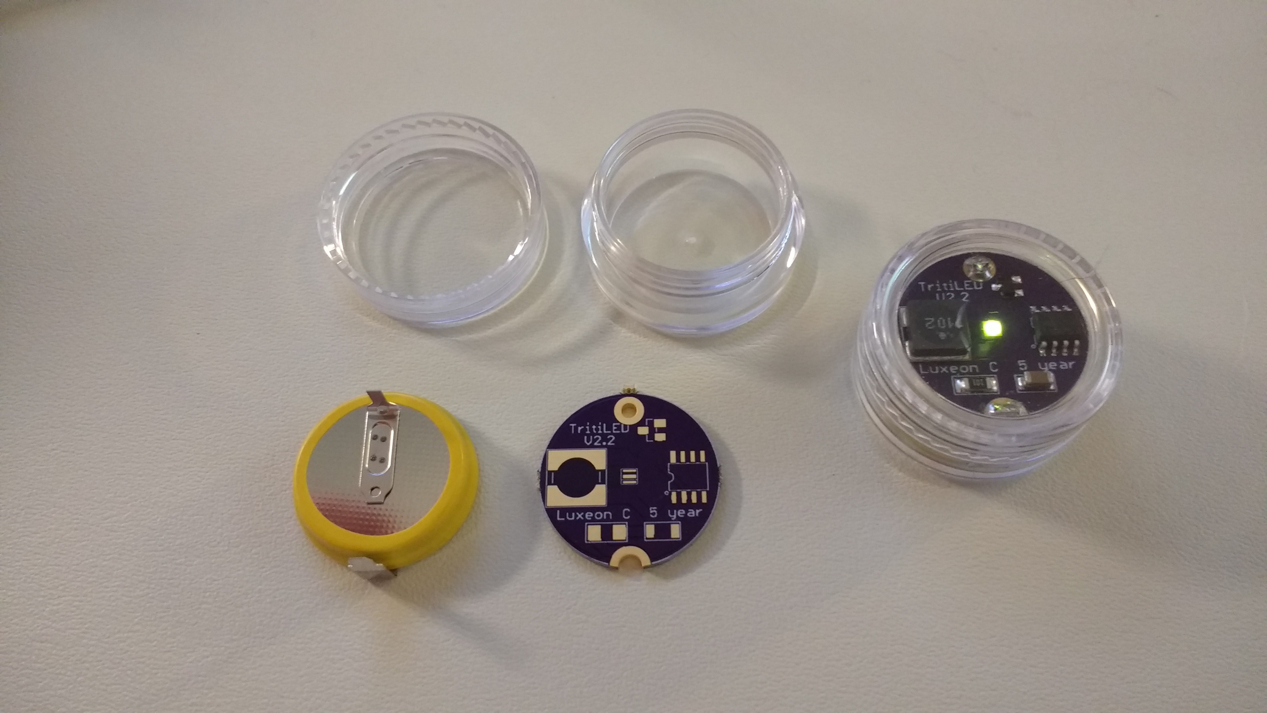
The PCB is designed to fit into a "5g" polystyrene jar, available cheaply on Amazon. These jars provide some water resistance - I imagine sealing the threads with some silicone caulk (or even epoxy) should thoroughly waterproof them. The CR2354 cell barely fits into the jar - you have to bend the positive tab a little to get it in there. The solder tabs make battery changes more difficult, but with a 560 mAh capacity, the cell should last around 5 years. The soldered battery connections also eliminate any issues with contact corrosion over time.
There is no switch and hence no blinking modes. In fact, the circuit has been stripped down to what I consider the bare minimum:
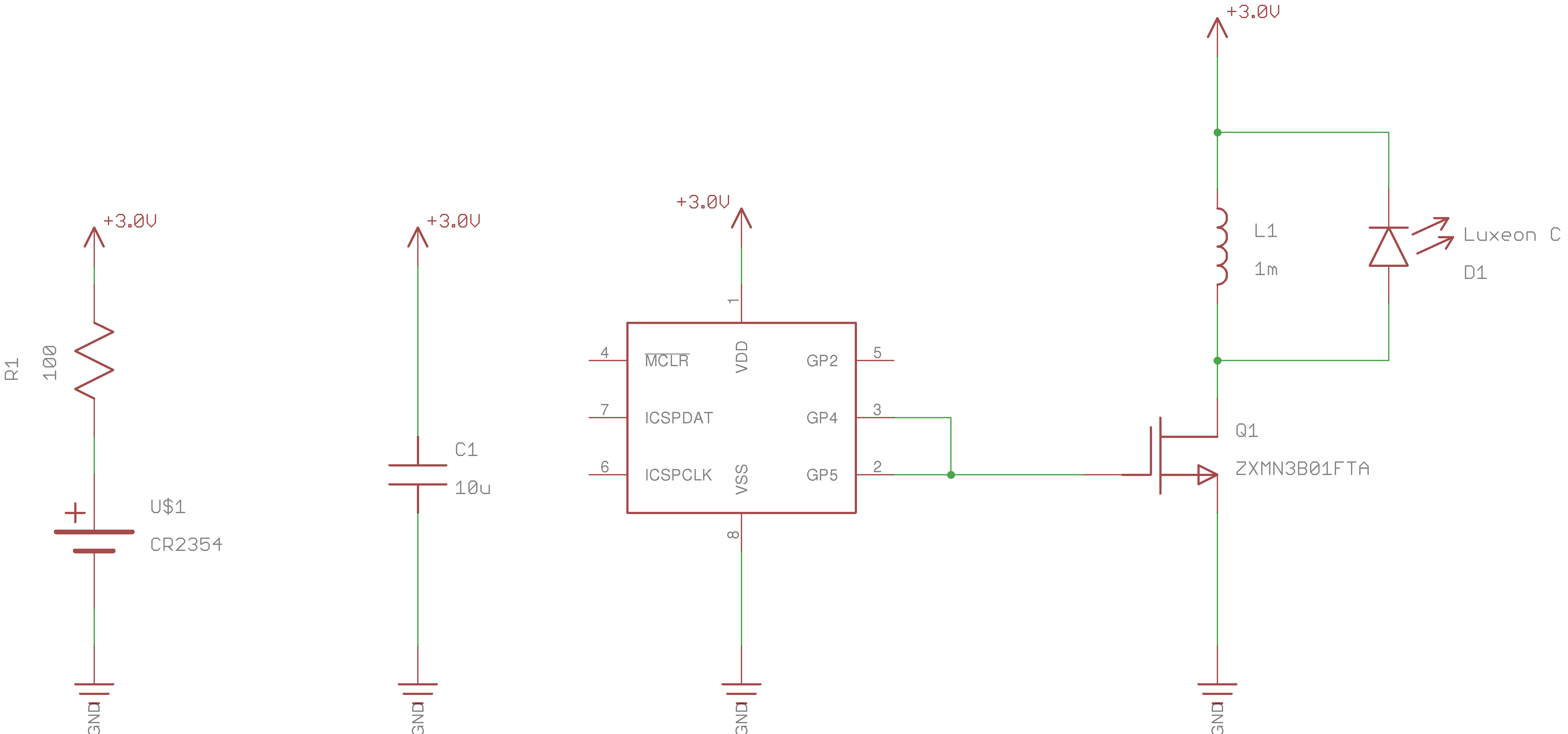
The assembled version shown uses a Luxeon C "lime" LED, which claims 152 lm/W - it's a bright yellow-green color, and very visible in daylight, but not as bright as some of the other cyan LEDs I have tried for dark-adapted eyes. I have some cyan and green (530nm) Luxeon C's to try next.
Here's an assembled one next to a V2.2:
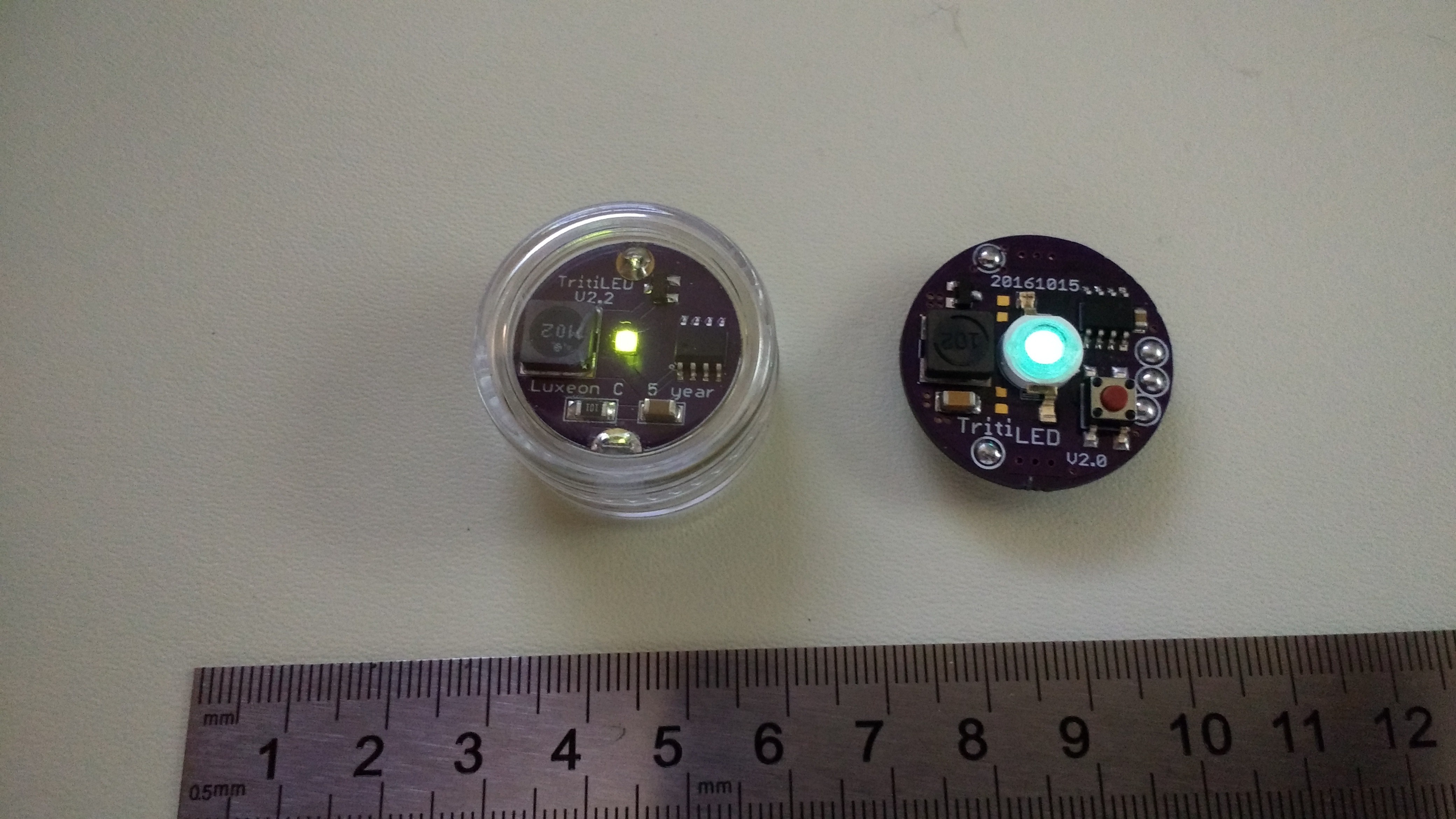
One problem with this PCB is that because the LEDs have a low profile, the inductor blocks some viewing angles on one side. The problem isn't terrible, but I thought I might avoid it by moving the LED to the other side. There is just enough space created by the battery tabs to clear the components on such a reversed board. Here was my first attempt:
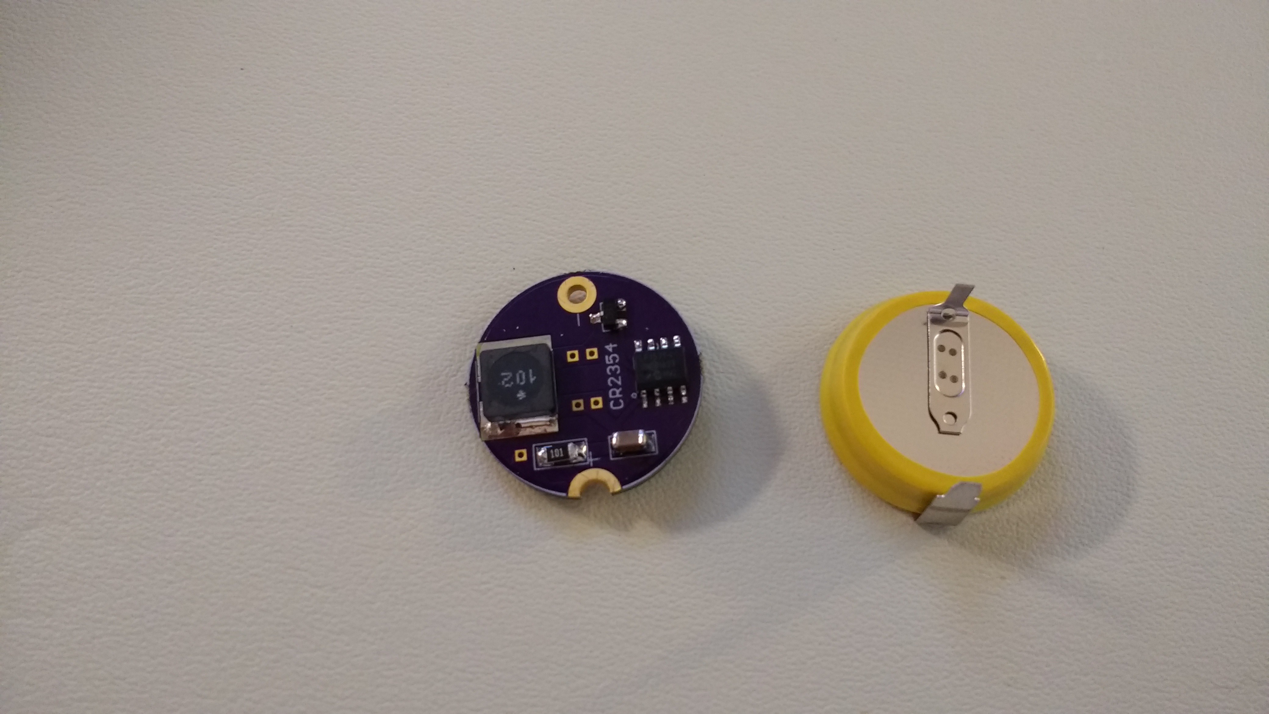
The LED is on the other side of the board:
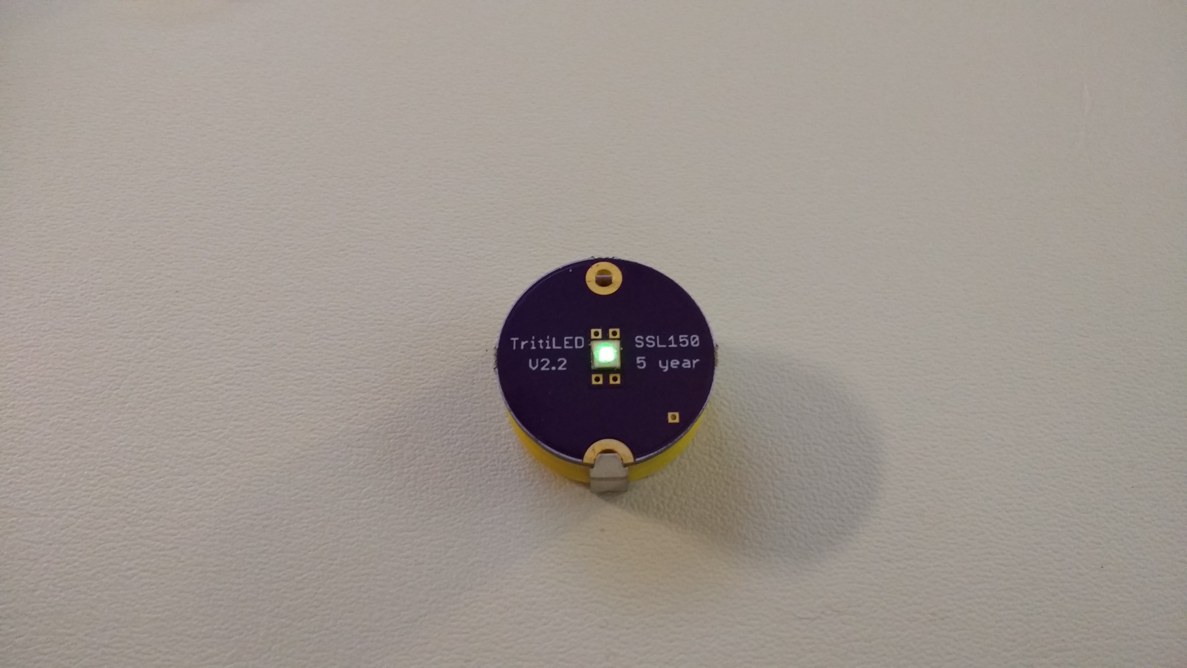
This creates a clean look and avoids issues with low-angle visibility, but introduces another problem: the board has components on both sides. You might be able to do this with a reflow oven, but I couldn't do it with a skillet, so I reflowed the LED, then manually soldered the rest of the components on the other side.
For this board, I also decided to try a new LED: the Osram Oslon SSL150, which boasts high efficiency and great viewing angles. Unfortunately, I didn't realize that this LED also contains a parallel reverse protection diode. This protection diode conducts whenever the MOSFET turns on, drawing huge (but brief) spikes of power. Unfortunately, this raises the consumption from around 14 uA to 850 uA! So, instead of five years of service, you get around one month. I won't be using these LEDs going forward.
I have a few more "reversed" boards like this being fabbed now - for Luxeon C and Cree XP-E2 LEDs. I like the little jars a lot. They're not as sexy as a custom enclosure, but they're functional. I'm hoping to get a chance to test water-proofing them soon. The deepest I can probably manage easily is around 50ft at the bottom of the Great Sacandaga Lake.
I also picked up some "10g" jars, which are large enough to contain the original CR2032-powered V2.2's with room to spare, and will also fit tabbed CR2477 cells, which will run markers for around 10 years. The CR2477's are expensive, but 10 years is a long time.
The PCBs shown here (and more I haven't tested yet) are in the GitHub repo. I'll probably remove all the ones with SSL150 LEDs, because they're not worth building.
 Ted Yapo
Discussions
Become a Hackaday.io Member
Create an account to leave a comment. Already have an account? Log In.
@Ted Yapo Hi Ted, Just built some of the reversed XP-E2 boards with a tabbed cr2354. I really like the design, thank you for publishing it. I see a lot of flicker when I loaded the bare bones hex from git. Is this flicker expected? Also I should have realized the reversed boards do not fit in the 3g jars, I'm going to look for something just a tad bit deeper.
Are you sure? yes | no
I'm glad you like it.
Yes, the barebones image is flickery. For me, it appears to flicker worse in brighter ambient light. At night, I don't notice it that much. Hmm, I'm just realizing that there are only the two hex images in GitHub. There are probably a few other variations I could add - although they all are just minor tweaks to the code. I haven't measured the barebones image current draw with an XP-E2 LED, but if it's near the 3.6 uA or so I got with the Chanzon LEDs, you're possibly looking at 15 years of service. The 5-year estimate is based on a brighter, less blinky image. I'll look through what experimental code I have around here and push something into GitHub in the next day or two.
Oh, the board will "fit" in a 5g jar with the appropriate application of force, but you may not like the results. Two things happened on mine. First, I damaged the XP-E2 lens, which is made of some soft silicone, by screwing down the top right into it - I didn't realize how much you needed to push it down. You can just make out the mangled lens in this image:
also, I found that over time (like a few days to a few weeks), the jars develop small cracks when a CR2354 is inserted - it's just a little too big. So far, all six jars I've forced to accept a CR2354 have "held", but I don't know about their long-term health. I suspect they will eventually fall apart from these cracks. You can see them in the middle case in the image below. I should take some images in polarized light to really investigate the stress on the case.
So, I guess you're basically right, they don't quite fit in 5g jars, exactly. But they're so close, I keep thinking that maybe with some tweaking, or bending the cell tabs before soldering, or some other trick, I could make it work.
Are you sure? yes | no
All of the designs fit into the 10g jars, but they swim around in there. You could pad them out with some foam, but the 10g jars just look too big.
If you find another case idea, let me know.
Are you sure? yes | no
OK. I added the tritiled22_nobutton.{asm, HEX} files in GitHub. Brighter with less flicker and these estimated runtimes:
;;; CR2032 (220 mAh): 2 years
;;; CR2354 (560 mAh): 5 years
;;; CR2477 (1000 mAh): 10 years
This is the code I've been running the single-mode versions with. It was sitting in my local repo un-commited. Duh.
YMMV, and it's always good to double-check the current drain before you solder on the cells. Let me know if you find something wrong.
Are you sure? yes | no
Im reading 15.2uA with the tritiled22_nobutton. It is brighter with a lot less flicker. Thank you.
Are you sure? yes | no
OK, one last thought. Polystyrene has a glass transition temperature of around 90-100C. Maybe if you dip the jars in boiling water before inserting the board, they will stretch slightly to fit it. As long as the top still screws on, I think it might work.
Another possibility is annealing the case after forcefully inserting the board. According to the Panasonic Lithium Battery Handbook (https://www.mouser.com/pdfdocs/PanasonicBatteries_LithiumHandbook.pdf), the CRxxxx coin cells are only rated for service to 60C, but the BRxxxx are rated up to 125C. Maybe the CRxxxx wouldn't get cooked if the jar were briefly dipped in boiling water to anneal the case?
Are you sure? yes | no
Hi,
Thanks for all this information and for the upload of the less flicker code. I will try it out on my board. I realized my issue with the 3g jars, they are completely different than your jars! Mine have about 2mm stolen from the bottom of it, while yours have a flush bottom. See the picture below. (note: I got lucky/unlucky catching the led exactly while it was off) (https://imgur.com/a/hVF1l) Is it possible to share the exact link you bought your jars from? I got mine from amazon but there appears to be a few versions with different bottoms. Mine will not work as the silicone lens is completely above the jar's screw threads.
I like the idea about annealing the polystyrene. I will give that a go after I build up the rest of my boards.
Im reading 4.3uA on the board with the barebones from before your upload. I'll report back when I flash the new code.
Thanks
Are you sure? yes | no
I think we were both confused about the "3g" vs "5g" vs "10g" jars before - the boards fit into 5g jars. I edited my comments below to reflect this.
It looks like I made the same mistake in the log above; I'll correct that, too.
Here is the link to the 5g jars I bought from Amazon:
https://www.amazon.com/gp/product/B012AO3DB6
Sorry if you have a bunch of "3g" jars around now. Maybe find some smaller batteries ? :-)
Are you sure? yes | no
Hi Ted,
No worries, your idea on the glass transition temperature got me thinking about heating the housing up and adding a small protrusion to clear the led. The batteries and circuit board fit in the diameter of the 3g jars I have but not in the Z height. I used my smd hot air tool and just heated locally the spot where the led sits, then used a blunt object to push a crater upwards. It worked well but there is definitely a lot of stress added to the area as it appears to be micro-fracturing now. Just like you have described above. (https://imgur.com/a/SRSeS)
I'll order some of the 5g jars and see how they work. Also ordered a 8 soic clip from amazon so I can program these boards faster.
Thanks
Are you sure? yes | no
So the CR2354 has more capacity than the CR2032, by about 2x?
Are you sure? yes | no
Yes, around 2.5x the capacity for 4.5x the price. Tabbed cells are closer in price. CR2477's seem to be the largest available coin cells, but are even more expensive. Prices are for single quantity:
CR2354: 560 mAh $1.33 ($2.02 with tabs)
CR2032: 220 mAh $0.29 ($1.14 with tabs)
CR2477: 1000 mAh $2.39 ($4.22 with tabs)
The normal CR2032s are bargain priced, probably due to large volume and commodity status, being made by many manufacturers. That's why I originally went with the CR2032.
Once you go with tabbed cells, the cost seems roughly linear with capacity, and you are more or less paying directly for run-time. CR2477s would theoretically last around 10 years in this application, CR2354's about 5 years, and CR2032's 2+ years.
Are you sure? yes | no
Ted, go to the hardware store, take your plastic jar with you, and find an O right that will fit the jar. This will make the jar rain-proof for sure. That doesn't mean the jar will be leakproof at 33ft underwater for an hour. (Although it just might with 2 O rings and some vaseline.) Make sure to get SILICONE O rings, not rubber. Silicone lasts longer. Rubber doesn't like extremes of temperature, like if someone stores this in their cabin in 90F summers and -10F winters (common highs and lows for Michigan, where I'm at.)
Are you sure? yes | no
This is a good idea. I think you might need flat rings, though. The threads on the jars don't aren't that long, and I'm not sure there's enough engagement to handle the thickness of a normal o-ring. I have an assortment package of rings somewhere I can try to find a fit.
Are you sure? yes | no
You can put a flat ring inside the lid, or an O-ring on the threads. Push the O ring down on the threaded part until it doesn't go down anymore. O rings come in different thicknesses. There are flashlights and match cases that use this method, including diving lights. But diving lights typically have a lower tolerance between the 2 pieces, and use 2 O rings.
Are you sure? yes | no
Are you sure? yes | no
That is a good deal - unless they're very old. CR-chemistry cells are supposed to have a 10-year shelf life, so I guess you could get some a couple years old for 5-year devices and still be OK.
For CR2477's that you expect to last 10 years, you probably want fresh ones. Even DigiKey shipped me an older one in a recent order. Two cells had recent 2017 codes, and one of them had a 2016 code. For most applications, you might not care, I guess, but still. It's like buying over-ripe bananas.
I'll look around for deals like that. For $5 I could take a chance.
Are you sure? yes | no
Are you sure? yes | no