Ted Yapo
-
V3.0 Prototype Tests: 1-10 year run times
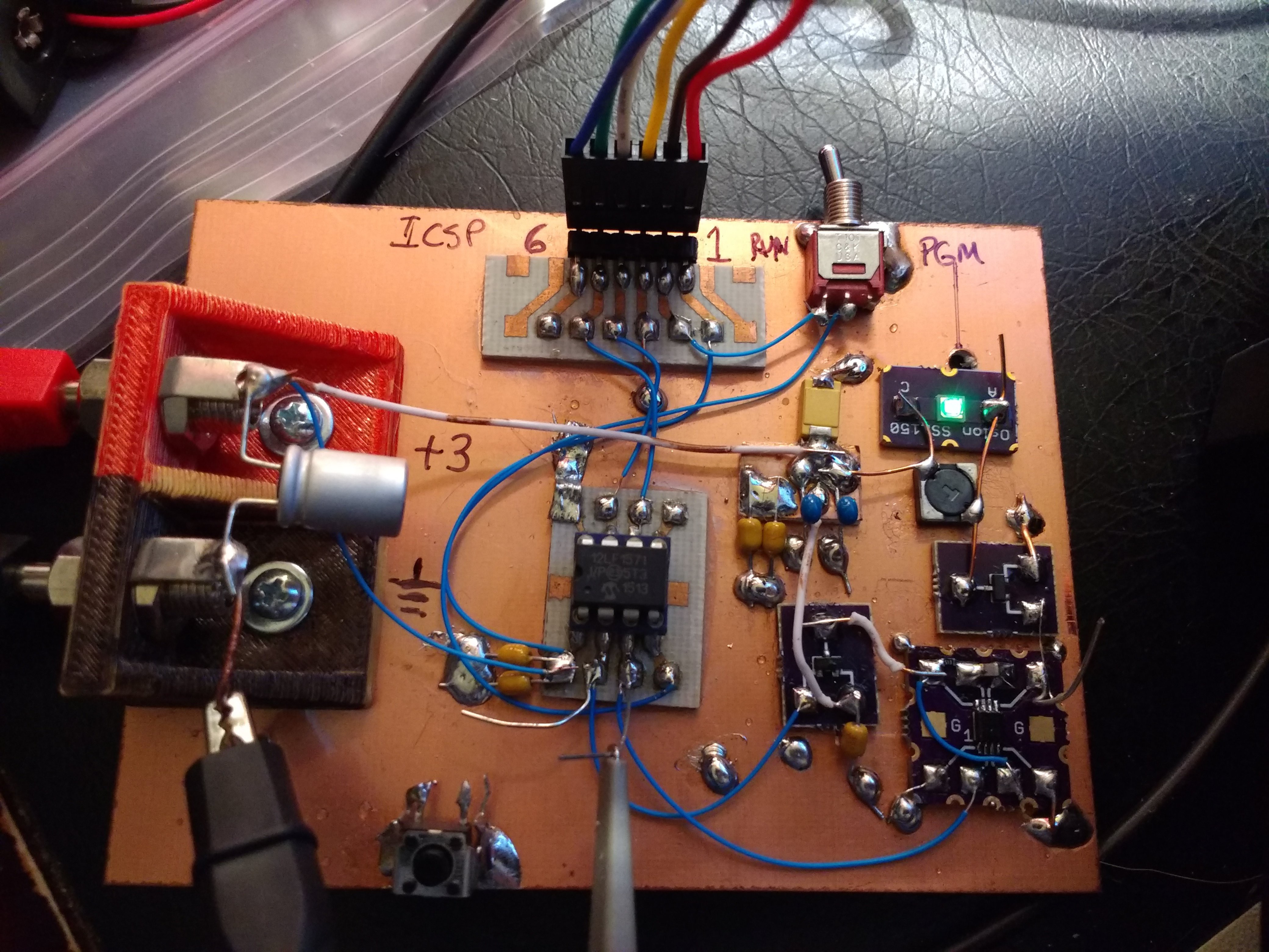
12/28/2017 at 03:41 • 0 commentsI prototyped the V3.0 circuit, re-using one of the V2.x breadboards. A few #Ugly SMD Adapters hold the 74LVC1G123 monostable, OSLON Signal Verde LED and SOT23 MOSFETs.
![]()
I tested the circuit at various pulse frequencies, and fit a line to the current drain. The resulting equation is:
where f is the pulse frequency. Since there is a fixed cost of 1.15uA, the circuit is more efficient for higher frequencies (larger current drains and brighter LED). This equation is close enough to get you in the ballpark when tuning for a specific current drain (or lifetime), but then you may need to tweak the frequency by a Hz or two to fine-tune.
Using the above equation and some manual fine-tuning, I came up with the following pulse frequencies for various run-times with a CR2032 cell. The cell capacity is assumed to be 220 mAh, and the run-time calculated as:
Frequency (Hz) Current (uA) Runtime (years) Notes 262 25.0 1.0 123 12.4 2.0 78 8.15 3.1 55 6.12 4.1 42 4.96 5.1 just flickering 32 4.06 6.2 noticeable flicker 26 3.53 7.1 noticeable flicker 21 3.07 8.2 noticeable flicker 17 2.71 9.3 noticeable flicker 14 2.43 10.3 noticeable flicker 1 1.24 20.24 exceeds shelf life I threw in that last point (1Hz pulse rate) just because it's the limit of the code as currently written. Since the shelf life of CR-series cells is commonly taken to be 10 years, I don't think run-times beyond that point make sense to predict.
Of course, the frequencies shown here are just examples chosen to correspond roughly to integer year run-times. You are free to choose any frequency in between or exceeding these. As a test, I turned the frequency up to 5kHz (it measured 4.65 kHz on the scope), and the circuit consumed 405uA. The LED was very bright.
The brightness at 1- and 2-year run-rates seems equivalent to the V2.0 circuit with the single LED I've tested so far.
Here's the PIC code. It's not in GitHub yet. The code just sets up the PWMs and then goes to sleep. The WDT is set for a 256-second timeout, at which point it wakes and the PIC resets to re-initialize the state just in case some bits rot over the years.
;;; ;;; tritiled_v30.asm: ;;; PIC12LF1571 code for CR2032-powered LED glow marker ;;; ;;; 20171227 TCY LIST P=12LF1571 #include <p12lf1571.inc> ;;; ;;; adjustable pulse frequency parameter ;;; FREQ equ .123 ;;; calculated and fixed parameters PHASE1 equ .0 PHASE2 equ .0 DUTY_CYCLE1 equ .2 DUTY_CYCLE2 equ .1 OFFSET_COUNT equ .1 PERIOD_COUNT equ (.31000 / FREQ) ERRORLEVEL -302 ERRORLEVEL -305 ERRORLEVEL -207 __CONFIG _CONFIG1, _FOSC_INTOSC & _WDTE_ON & _PWRTE_OFF & _MCLRE_OFF & _CP_OFF & _BOREN_OFF & _CLKOUTEN_OFF __CONFIG _CONFIG2, _WRT_OFF & _PLLEN_OFF & _STVREN_OFF & _BORV_HI & _LPBOREN_OFF & _LVP_ON ORG 0 RESET_VEC: nop nop nop nop INTERRUPT_VEC: BANKSEL ANSELA movlw b'00000000' ; all digital I/O movwf ANSELA BANKSEL LATA clrf LATA BANKSEL TRISA clrf TRISA ; set all lines as outputs BANKSEL WDTCON movlw b'00100101' ; WDT 256s timeout movwf WDTCON BANKSEL APFCON movlw b'00000011' movwf APFCON BANKSEL PWM1CON movlw b'00100001' ; PWM2 triggered with PWM1 movwf PWM2OFCON movlw HIGH(PHASE1) movwf PWM1PHH movlw LOW(PHASE1) movwf PWM1PHL movlw HIGH(PHASE2) movwf PWM2PHH movlw LOW(PHASE2) movwf PWM2PHL movlw HIGH(DUTY_CYCLE1) movwf PWM1DCH movlw LOW(DUTY_CYCLE1) movwf PWM1DCL movlw HIGH(DUTY_CYCLE2) movwf PWM2DCH movlw LOW(DUTY_CYCLE2) movwf PWM2DCL movlw HIGH(PERIOD_COUNT) movwf PWM1PRH movlw LOW(PERIOD_COUNT) movwf PWM1PRL movlw HIGH(PERIOD_COUNT) movwf PWM2PRH movlw LOW(PERIOD_COUNT) movwf PWM2PRL movlw HIGH(OFFSET_COUNT) movwf PWM1OFH movlw LOW(OFFSET_COUNT) movwf PWM1OFL movlw b'00000011' movwf PWMLD movlw b'00000010' movwf PWM2CLKCON movlw b'00000010' movwf PWM1CLKCON movlw b'00000000' movwf PWM1OFCON movlw b'11010000' movwf PWM1CON movlw b'11000000' movwf PWM2CON sleep ; halt here - PWM generates pulses reset ;; fill remainder of program memory with reset instructions fill (reset), 0x03fe-$ END -
Tuning V3.0
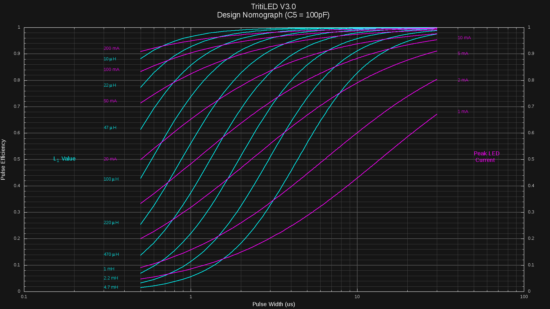
12/27/2017 at 19:14 • 0 commentsThe V3.0 circuit allows you to tune the pulse width and repetition rate independently. Throwing in inductor size and peak current, and you have a four dimensional space in which to choose an operating point. To simplify the design process, I condensed three of the variables (pulse width, inductor size, and peak current) into a nomograph showing the efficiency of each pulse:
![]()
The y-axis shows the efficiency of each LED pulse, just considering the per-pulse overhead of the PIC and monostable. The overall electrical efficiency will be somewhat less than this value due to an approximately 1.1uA baseline current for the PIC, plus any losses in the inductor and MOSFET. This chart also assumes a 100pF capacitor for the monostable; the resistor is chosen based on the desired pulse width from the formula:
I experimentally determined k = 1.28 for C = 100pF at 3V (the datasheet charts don't include this value).
How To Use
Don't panic.
The chart is easy - you use it to choose an inductor size and pulse width based on the peak LED current you want. The vertical axis reads the pulse efficiency, which is to say, how much energy goes into the LED vs how much is wasted in the PIC and monostable during a pulse. You want to maximize this efficiency. The horizontal scale shows the monostable pulse width.
There are two sets of lines on the chart. The cyan lines, labeled on the left, represent different inductor values. For example, following the 470uH line to a 3us pulse width shows that around 84% of the energy used during a pulse can get to the LED; the remaining 16% being wasted by the PIC and monostable.
The magenta lines (labeled on either side) represent the peak current through the LED. Using the example above of 470uH and 3us, we see that this point is intersected by the 20mA line, so the peak current through the LED for this combination is 20mA.
In practice, you typically know the desired LED peak current, and want to choose the inductor and pulse width. So, here's another example: you know your LED is most efficient with peak currents of 50mA. To get the most efficient drive, you examine the 50mA magenta line, and evaluate each possible inductor value. If you have a 1mH inductor available, you can get 50mA pulses at about 17us with 98% efficiency. On the other hand, if you choose a 100uH inductor, you'll end up with around 1.7us pulses and 88% efficiency. That's it.
Complications
So, the answer seems easy: choose the 1mH inductor, which is more efficient. In reality, you may want to choose a smaller inductor since it will allow you to run at lower currents without visible flashing. For a given current, using a larger inductor means more energy per pulse, so for a specified current drain, you will need to choose a slower flash rate, which may become visible.
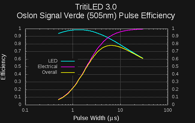
A second complication is that the optimum LED current may not turn out to be the best choice considering the monostable pulse overhead. This is especially true for small LED currents. As an example, the OSLON Signal Verde LED I have been testing has a current around 4mA for peak efficiency. Unfortunately, driving this LED at 4mA with a reasonable 1mH inductor results in around 40% pulse efficiency (60% of the energy used by the PIC and monostable). So, you can do better by choosing a larger current: you trade electrical efficiency for LED efficiency to get a better overall efficiency. You can see this tradeoff directly in a plot of the three efficiencies (electrical, LED, and overall) vs pulse width for a 1mH inductor:
![]()
Although the LED would perform best with a pulse of approximately 1.5us, and the rest of the circuit at 10 or more, the combination performs best at around 6.5us. Here, the electrical efficiency is over 90%, while the LED efficiency is 86%. Multiplying the two reveals that the circuit is emitting 78% of the possible light for this LED given this current drain.
Evaluating the performance of such a choice requires detailed information about the LED efficiency curve. I've written some Octave code to incorporate the measured efficiency curves, and the result is that you can achieve a maximum 91% electrical efficiency by driving this particular LED at 19.5 mA, using a 1mH inductor with a 6.5us pulse. This 91% efficiency is a limit in the case of high pulse rates (equating to hight brightness and high current drain). Considering the fixed PIC overhead, the overall electrical efficiency drops to 83% at a 2-year CR2032 lifetime (12.5 uA) with a pulse rate of 164 Hz. Going to a 1-year CR2032 lifetime (25uA) increases the electrical efficiency to 87%, using a pulse rate of 344 Hz.
Since the pulse frequency is determined by a 16-bit PWM, it can be adjusted very accurately. For example, changing the pulse frequency to 56Hz drops the current drain to 5uA, for a 5-year runtime on a CR2032 at an electrical efficiency of 71%. Of course, the LED is much less bright. If you extend the runtime much further, the flashing becomes noticeable. For example, you can set the pulse frequency to a visibly flashing 21Hz, reducing the current to 2.5uA, and the LED should stay lit for 10 years on a CR2032. At this point, the PIC overhead really starts to take a toll: the electrical efficiency at this 10-year rate is only 52%. But, the light stays on for a decade.
Do I really have to go through all that??!
No. I've chosen a small set of LEDs I'm designing for, and will choose all the components for each one making what I think are reasonable trade-offs. I'll publish complete designs for each one after they've been tested and confirmed.
As I release the designs, I'll also present the measured current drains vs pulse frequencies and estimated efficiency numbers for a variety of run-times from 1 to 10 years on a CR2032.
-
Quick Link: 40 Year Battery Life?
12/26/2017 at 19:44 • 0 commentsThe good people at Tadiran seem to think that a 40-year battery lifetime is possible with LiSOCl2 cells. I think it's an interesting read, but I'll probably stick with CR-series cells (LiMnO2) for the moment.
http://www.tadiranbat.com/is-a-40-year-battery-life-a-reality.html
-
V3.0 Design
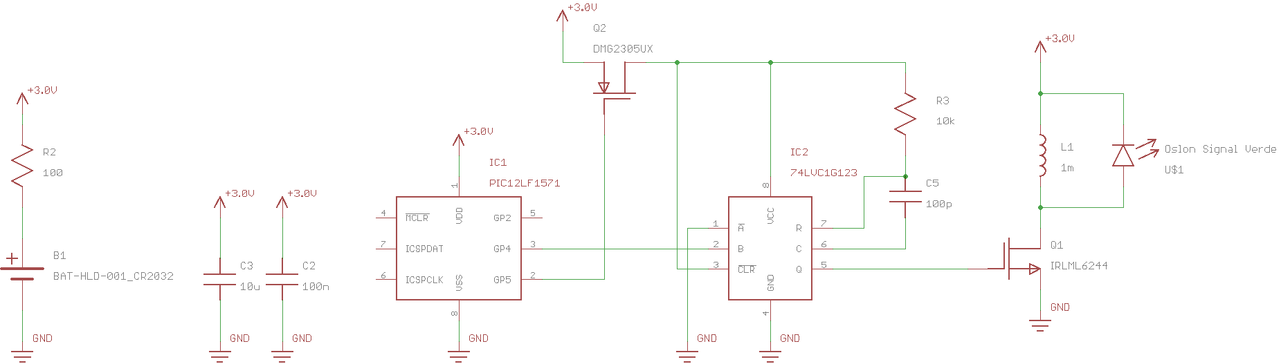
12/23/2017 at 18:42 • 0 commentsHere's the circuit for V3.0
![]()
In this design, a PIC12LF1571 controls the LED using two 16-bit PWM outputs. The PWMs continue to run even in sleep mode, and to save power, are running from the 31kHz LFINTOSC. The PIC will only wake every few minutes or so to re-initialize any RAM that may have become corrupt, and maybe change the PWM frequency based on the supply voltage (to maintain a constant brightness).
The downside of using the PWMs running from the 31kHz oscillator is that that shortest pulse that can be created is around 30us, far too long for most LED/Inductor combinations. So, the PWM output is used to trigger a 74LVC1G123 monostable which creates the necessary short pulse. In the first batch of boards, I'm using a OSLON Signal Verde LED, which requires a peak current of around 4mA for optimum efficiency. Using a 1mH inductor, the required pulse width is 1.2us, so a 100pF capacitor and 10k resistor are used for the 74LVC1G123's RC.
The big problem with the 74LVC1G123 is that the quiescent current drain is specified at 20uA. This is several times the entire current budget for the glow marker. So, to save power, the PWM1 output is used to gate power to the 74LVC1G123. The normally-high PWM1 output goes low around 30us before the LED pulse, applying power to the monostable through Q2, a P-channel MOSFET. PWM2 is synchronized to PWM1, and triggers the monostable once it has had a chance to power-up. The datasheet for the 74LVC1G123 mentions that it contains circuitry to prevent glitches during power-on.
The notion of using the PWM instead of code to drive the LED pulses was suggested by @MarkRD in late July of this year: the rest of the design follows from that.
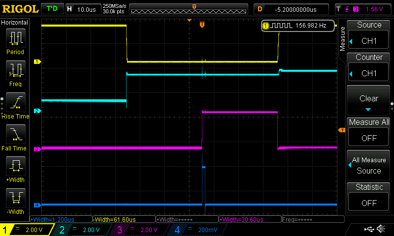
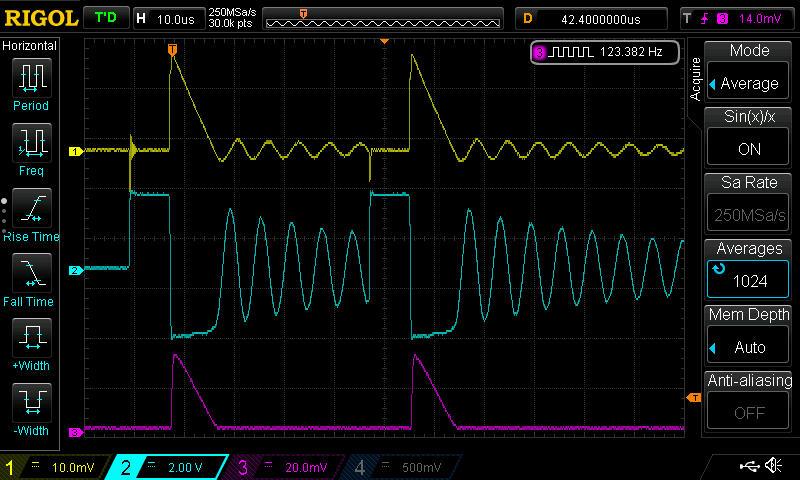
Here are some scope traces from a breadboarded version:
![]()
The PWM1 output (top trace; yellow) is normally high, and is pulled low to apply power to the monostable. The monostable's Vcc supply (second trace; cyan) rises quickly as the P-MOSFET switches on. PWM2's output (third trace; magenta) is synchronized to PWM1, and occurs 30us after the monostable is powered on. The monostable output (bottom trace; blue) is a nice 1.2us pulse (actually measured as 1.36 on a zoomed-in view).
The measured current drain for just the PIC PWMs (no monostable) is 1.12uA with an output frequency of 150Hz. Adding the monostable brings the total drain to 1.98 uA at 3V. The current drops significantly at lower supply voltages. I measure 1.27uA with the monostable at 2.0V.
Although these currents aren't quite as low as I'd like, this architecture brings a lot of flexibility. Through the choice of the RC time constant for the monostable and inductor value, the peak current can be accurately matched to the efficiency curve of the LED. Once that has been done, the LED brightness and total current drain can be adjusted with very fine control by changing the 16-bit PWM frequency. At around 150Hz blink rate, the brightness (and current) can be adjusted in sub-1% steps. So, you can use a wide variety of LEDs, with the circuit tuned to the characteristics of each one.
I haven't built a complete prototype yet, so there may still be some surprises. I have some PCBs coming from OSH Park, and although they need a bit of rework (I found a bug), I should be able to complete a few prototypes soon. A corrected PCB has already been ordered.
-
Version 3 Beginnings
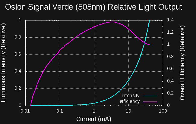
12/22/2017 at 17:08 • 0 commentsIn honor of the Coin Cell Challenge, I thought I'd put together a V3 design. As if by providence, DigiKey just started stocking the Oslon Signal series LEDs. Of particular interest is the Verde color, with a 505nm output peak nicely coinciding with the scotopic (dark-adapted) peak sensitivity of the human eye. I re-assembled the #Automated LED/Laser Diode Analysis and Modeling system and measured the relative efficiency of this LED:
![]()
I was quite surprised to find that this LED has a peak efficiency between 3-4mA. From the datasheet, the recommended current is 350mA, and the max 1000. I didn't have a good heatsink solution, so I only ran the LED up to 40mA for testing.
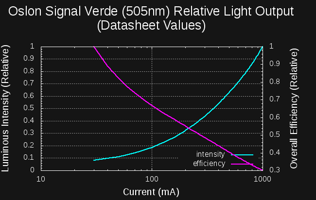
There's enough information in the datasheet graphs to calculate the relative efficiency for currents greater than 30mA, so I digitized the If vs Vf and relative intensity vs If graphs on page 9. Here's a plot like the above, but created from the datasheet values:
![]()
According to the graphs in the datasheet, the efficiency continues to drop with increasing current. Between the measurements and the datasheet values, it appears that this LED is about 4.5x as efficient between 3-4mA than it is at the maximum of 1000mA. Even compared to the recommended current of 350 mA, the LED is still 3x more efficient at around 3 mA.
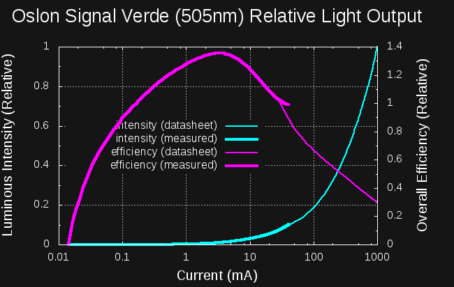
To see how the curves correspond, I scaled the relative scales so that they match at 30mA:
![]()
The measurements show a slightly higher efficiency than the datasheet at 40mA, but considering the datasheet curves were calculated with values scraped from plots, I'm not overly concerned about it.
Oddly, the datasheet says not to use the LED under 30 mA - I have no idea why there's a minimum current rating for an LED. Does anyone know?
I'll admit that I was lazy with a lot of the recent LEDs I used on V2 boards, assuming they would have their efficiency peak around 20mA. I'm glad I took a closer look at this one before completing the V3 design.
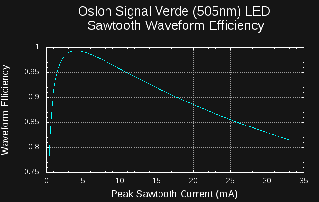
Optimal Sawtooth Waveform
Assuming an inductor-flyback drive like the V2 design, a little math gives the optimum peak for the sawtooth current pulse:
![]()
The ideal peak current is 4 mA, although the efficiency remains above 95% for currents up to 10mA, and above 90% until around 18 ma.
Since the current will fall with the coin cell voltage, I probably want to start the current a little higher to maximize efficiency over the lifetime of the cell.
-
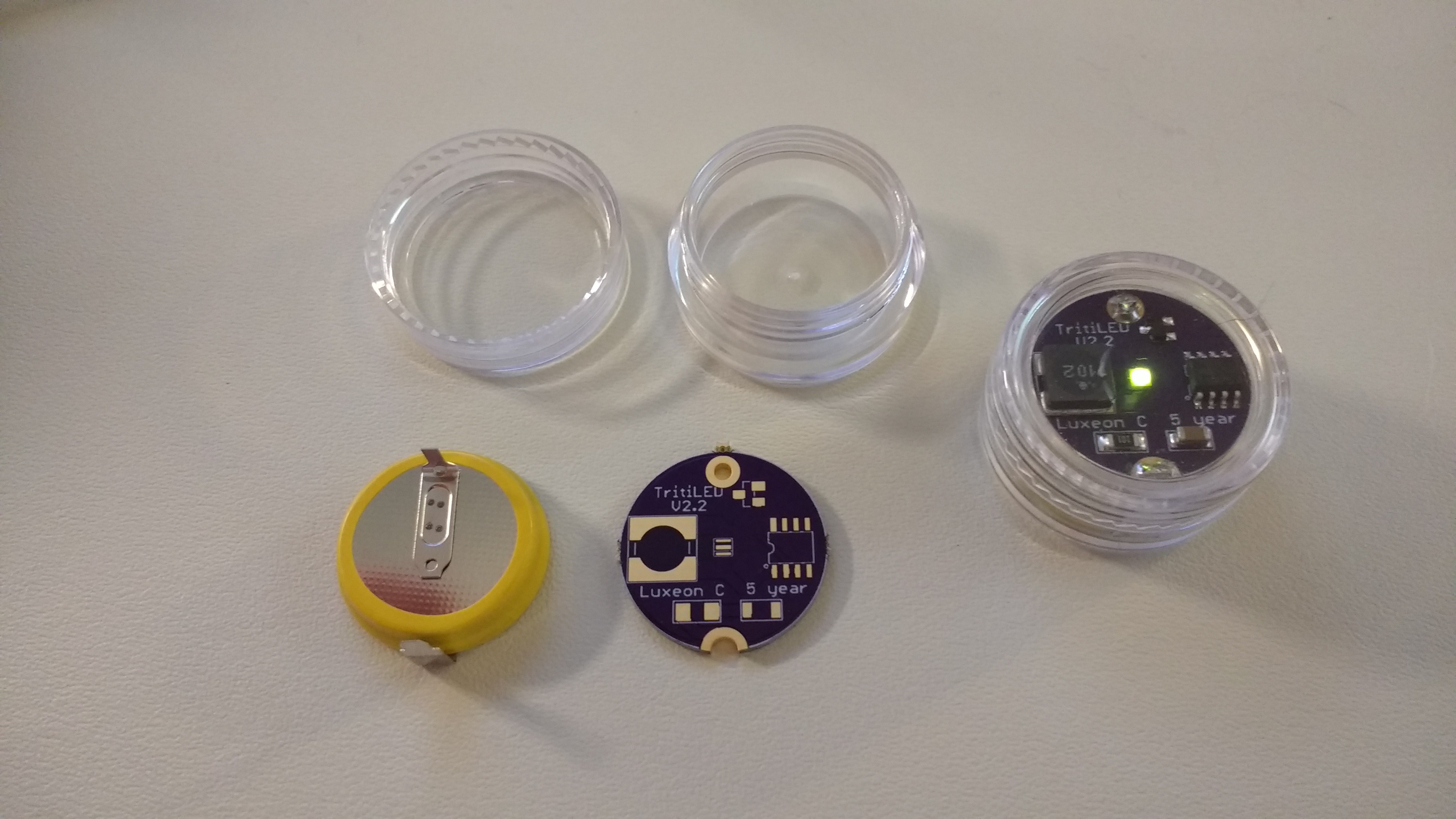
CR2354 Editions
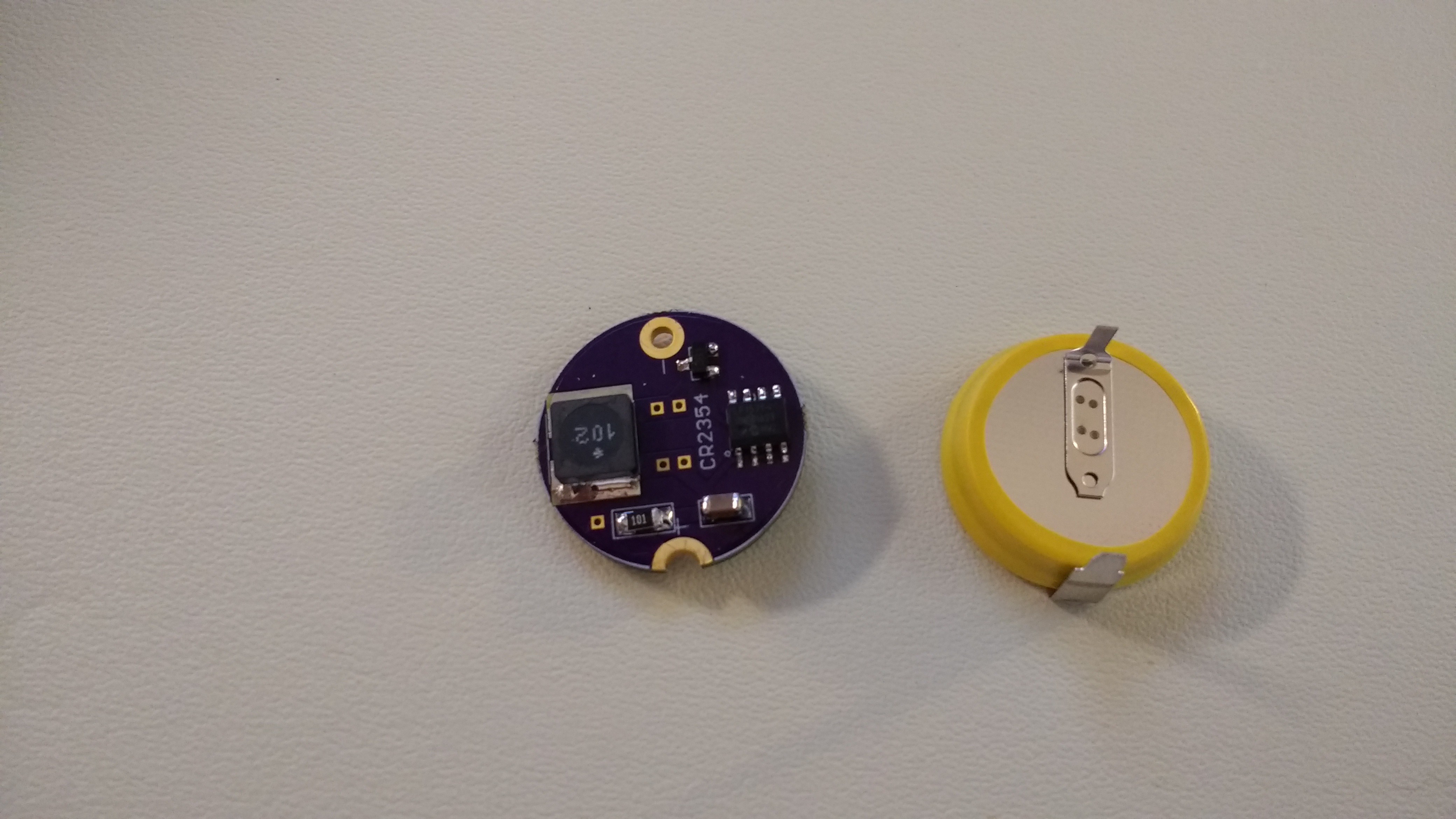
08/29/2017 at 18:02 • 17 commentsI built some experimental boards for use with solder-tabbed CR2354 cells:
![]()
The PCB is designed to fit into a "5g" polystyrene jar, available cheaply on Amazon. These jars provide some water resistance - I imagine sealing the threads with some silicone caulk (or even epoxy) should thoroughly waterproof them. The CR2354 cell barely fits into the jar - you have to bend the positive tab a little to get it in there. The solder tabs make battery changes more difficult, but with a 560 mAh capacity, the cell should last around 5 years. The soldered battery connections also eliminate any issues with contact corrosion over time.
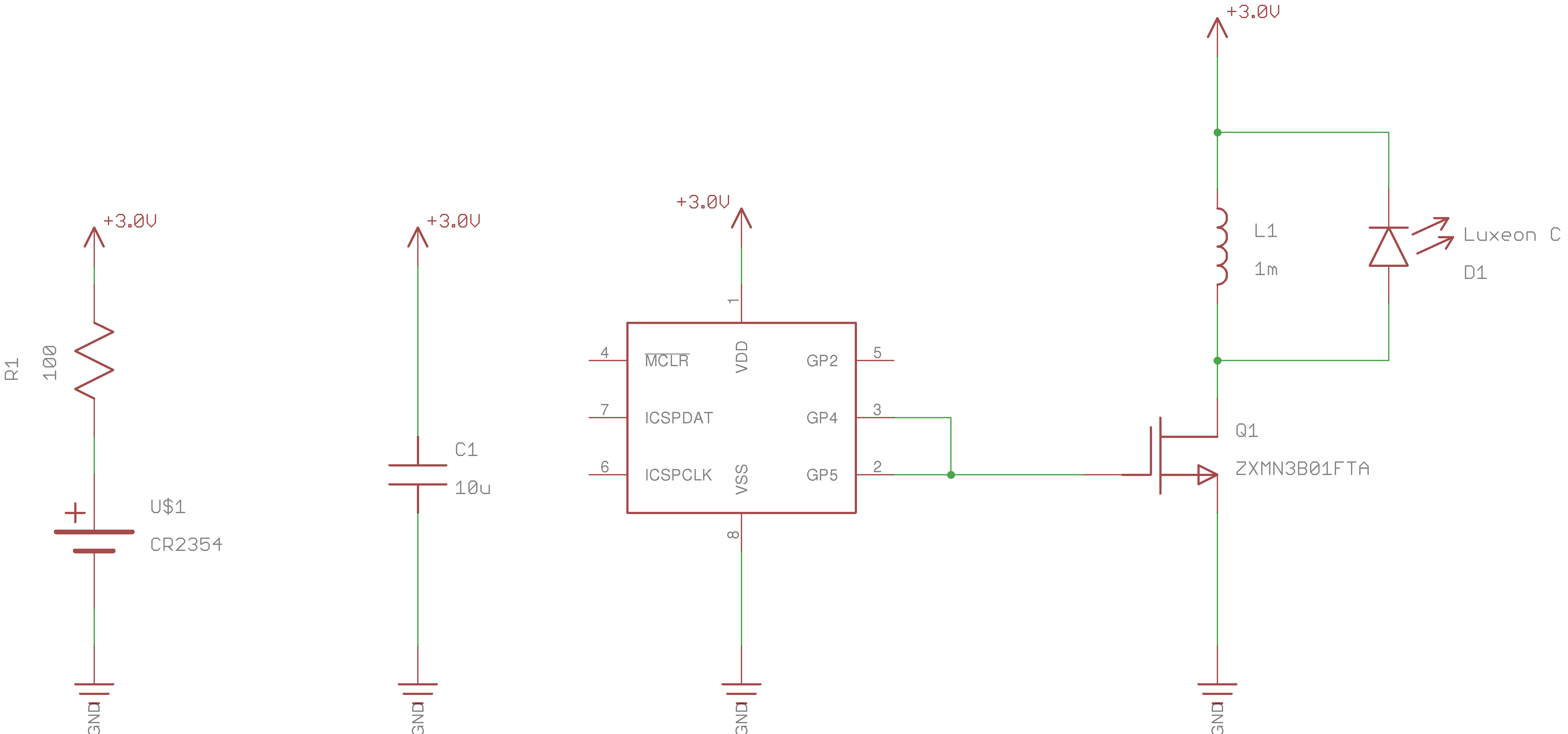
There is no switch and hence no blinking modes. In fact, the circuit has been stripped down to what I consider the bare minimum:
![]()
The assembled version shown uses a Luxeon C "lime" LED, which claims 152 lm/W - it's a bright yellow-green color, and very visible in daylight, but not as bright as some of the other cyan LEDs I have tried for dark-adapted eyes. I have some cyan and green (530nm) Luxeon C's to try next.
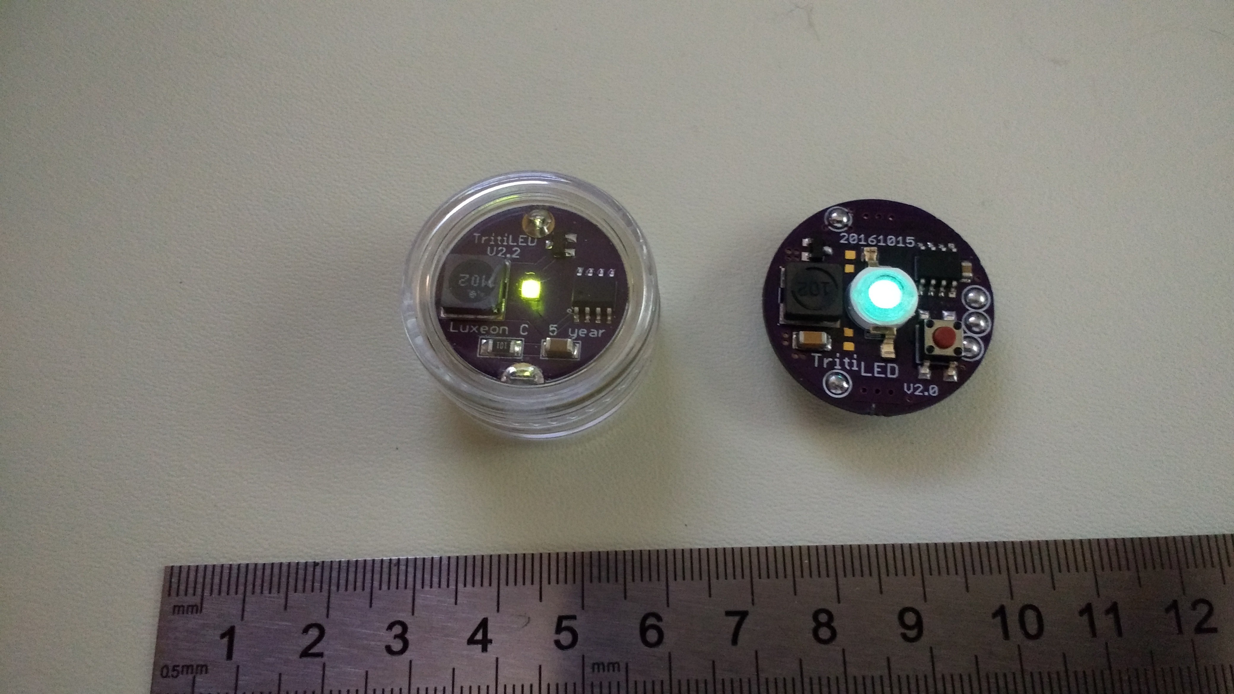
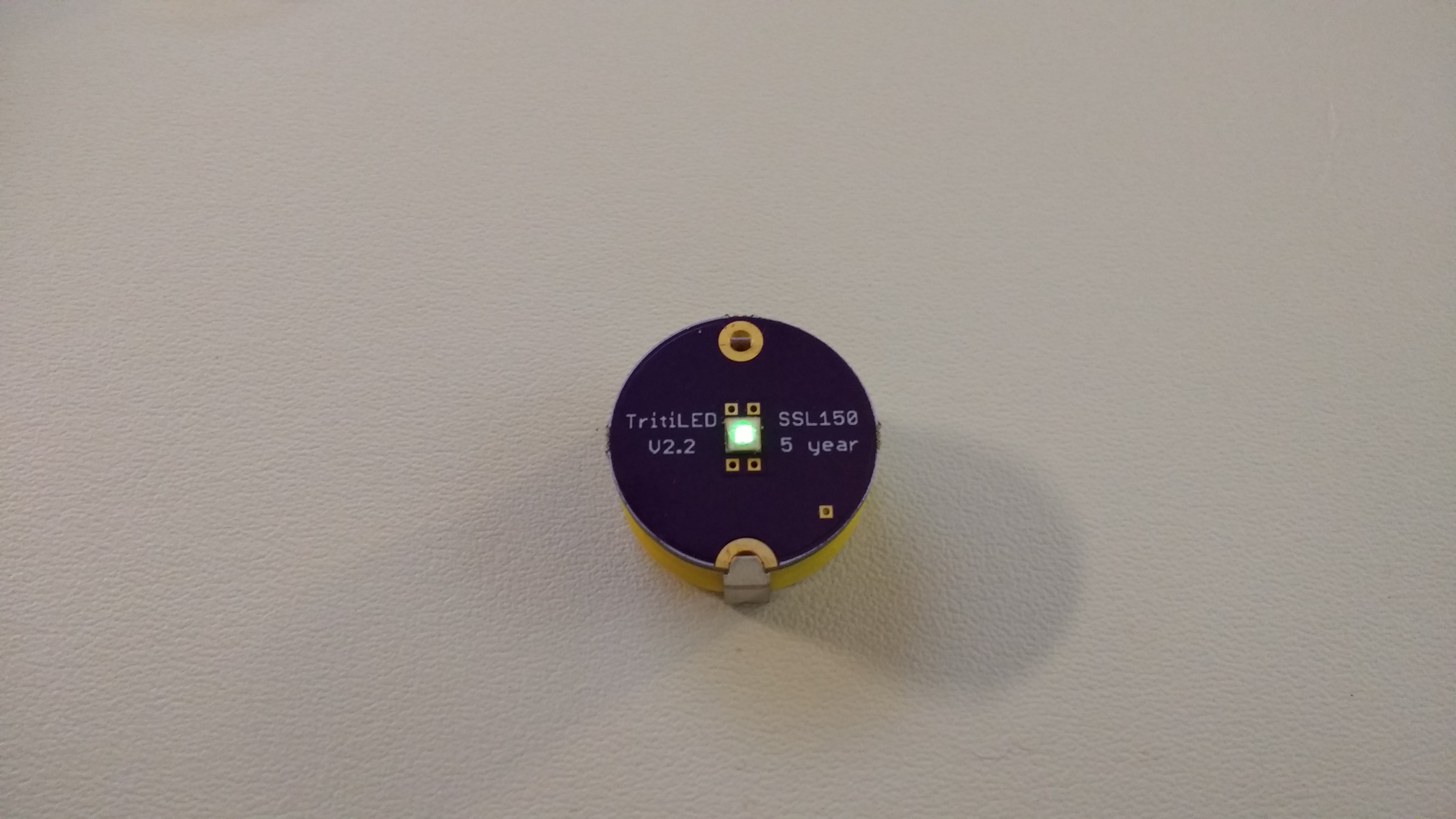
Here's an assembled one next to a V2.2:
![]()
One problem with this PCB is that because the LEDs have a low profile, the inductor blocks some viewing angles on one side. The problem isn't terrible, but I thought I might avoid it by moving the LED to the other side. There is just enough space created by the battery tabs to clear the components on such a reversed board. Here was my first attempt:
![]()
The LED is on the other side of the board:
![]()
This creates a clean look and avoids issues with low-angle visibility, but introduces another problem: the board has components on both sides. You might be able to do this with a reflow oven, but I couldn't do it with a skillet, so I reflowed the LED, then manually soldered the rest of the components on the other side.
For this board, I also decided to try a new LED: the Osram Oslon SSL150, which boasts high efficiency and great viewing angles. Unfortunately, I didn't realize that this LED also contains a parallel reverse protection diode. This protection diode conducts whenever the MOSFET turns on, drawing huge (but brief) spikes of power. Unfortunately, this raises the consumption from around 14 uA to 850 uA! So, instead of five years of service, you get around one month. I won't be using these LEDs going forward.
I have a few more "reversed" boards like this being fabbed now - for Luxeon C and Cree XP-E2 LEDs. I like the little jars a lot. They're not as sexy as a custom enclosure, but they're functional. I'm hoping to get a chance to test water-proofing them soon. The deepest I can probably manage easily is around 50ft at the bottom of the Great Sacandaga Lake.
I also picked up some "10g" jars, which are large enough to contain the original CR2032-powered V2.2's with room to spare, and will also fit tabbed CR2477 cells, which will run markers for around 10 years. The CR2477's are expensive, but 10 years is a long time.
The PCBs shown here (and more I haven't tested yet) are in the GitHub repo. I'll probably remove all the ones with SSL150 LEDs, because they're not worth building.
-
V2.2 for sale on Tindie!
08/29/2017 at 16:52 • 0 commentsYou can now buy V2.2 TritiLEDs on Tindie!
I have had people ask before if they could buy kits or assembled units, and I always had to say no. Now an enterprising individual has started producing them and making them available for sale - using the design files in this way is permitted by the open-source license (MIT). It's good to see: this is how open-source is supposed to work.
I should point out that I have no official affiliation with the seller on Tindie (Kontakt). I designed the original, but it's someone else who is selling them. This is all good, with the one exception that I can't provide support for any devices you buy from someone else.
So, if you want one (or more), you can now just buy it (them).
-
V2.2 New LED Editions
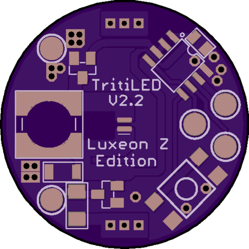
08/16/2017 at 17:37 • 0 commentsI wanted to experiment with some new LEDs, and decided that making new PCBs was the shortest path to victory, so I created 3 new editions of the V2.2 PCBs this morning. The first uses the Luxeon Z LED from V1.x. I mostly created this version because I have a small stock of these LEDs who keep complaining that I never used them. Interestingly, all three LED packages I added today are smaller than the Chanzon package, and would allow a PCB shrink, but I kept everything else on the board the same for compatibility with existing programmers and cases. I think V3 will be smaller.
![]()
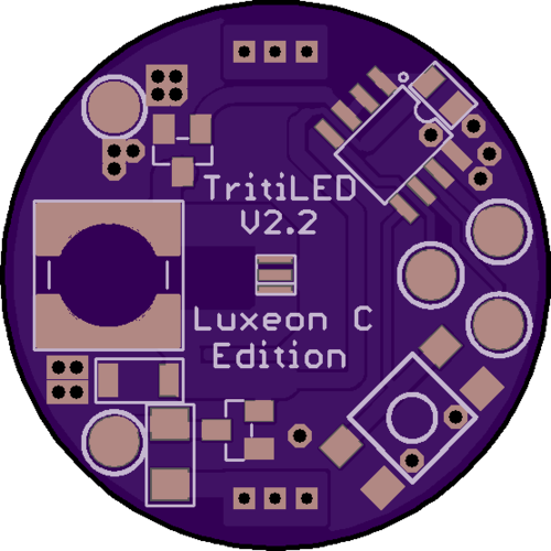
I also created a Luxeon C version. The "C" LEDs claim a much higher lm/W rating than the "Z" for some reason, so I am exited to try them. I have some cyan, green, and "lime" ( a phosphor-based green ) versions on order. If I had an integrating sphere and calibrated spectrometer handy, I could compare LEDs in a more principled way. As it stands, the best instruments I have at the moment are my own eyes, and a side-by side board comparison is probably the best I can do for now.
![]()
I initially dismissed phosphor-based white LEDs for this project because I'm obsessed with stimulating receptors at 505nm. I might be off-base here: a few of my collaborators have pointed out white LEDs with outstanding (photopic) efficiencies in excess of 200 lm/W. Of course, since lighting is driving the LED industry, white LEDs will continue to improve preferentially, while price gets driven down by competition and economies of scale. So, I'm going to try a few.
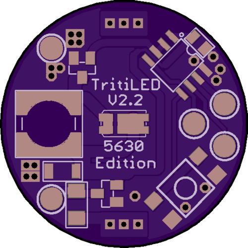
Efficient white LEDs are available in 5630 packages, so I made a board for those:
![]()
I'm particularly interested in two LEDs carried by Digikey, the Samsung LM561C, which boasts 212 lm/W (photopic) at a 5000K color temperature, and the Osram Duris E5, at 205 lm/W and 6500K. They're both less than $0.50 in singles, compared to the $0.80 Chanzon's and $2.75 Luxeons.
The design files and gerbers are in the GitHub repo, but I haven't shared the OSH Park links yet since I haven't tested the boards. I may have screwed up the packages - it wouldn't be the first time. Once the boards come back and I verify they work, I'll open them up and post the links.
I also fixed the inconsistent value of C2. In some places it was 1uF; in others 100nF. Either value will work fine: I finally made them all 100nF. I think.
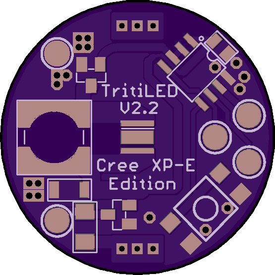
Update 20170817
I added a Cree XP-E(2) edition in the GitHub repo. This will accept the original XP-E series LEDs, or the improved XP-E2 versions. The XP-E2 green claims 113 lm/W at 525 nm, and these LEDs are available in a variety of colors (no cyan, though). I'm guessing that at 525 nm, it achieves a nice balance for either photopic or scoptoic vision. I'm also going to try a phosphor-white version.
![]()
Again, once I test the board out, I'll share the PCBs on OSH Park. I know the footprint is OK on this one since I've made other boards with XP-E LEDs on them. On a test board, this LED looks a little brighter than the Chanzon green, and has better viewing angles. The only issue is that the lower profile of this small LED means the inductor (and other parts on the board) block low-angle visibility for certain directions. Something to think about.
-
A Quick One: Tapped Inductors
07/29/2017 at 15:59 • 11 commentsI have been thinking of ways to avoid the issues of the inductor/LED arrangement, which constrains the current pulse width. This morning, I worked through some LTspice simulations using tapped inductors to get different input/output current ratios:
![]()
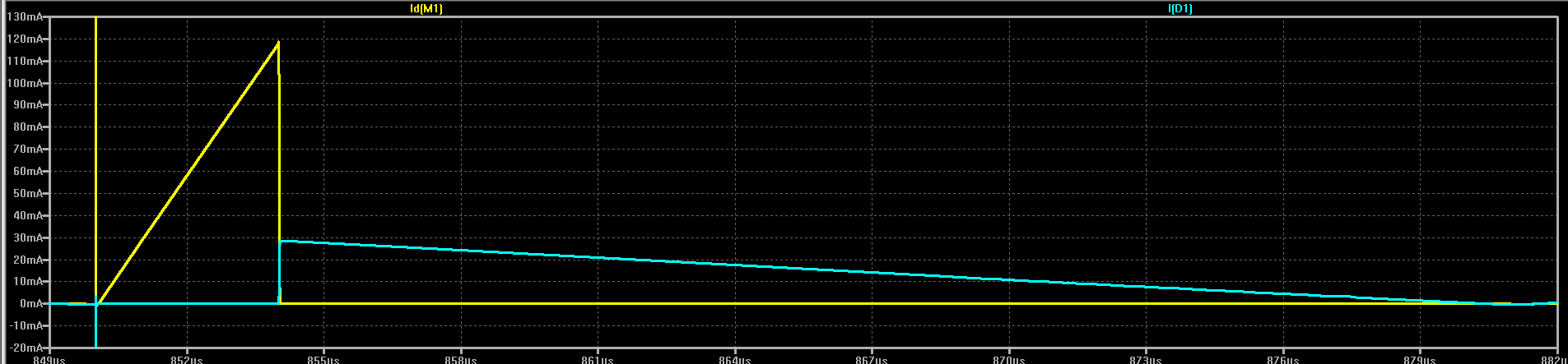
In the schematic, L1 and L2 are magnetically coupled by the K1 coefficient (1) simulating a tapped inductor - this isn't the same as two separate coils. In this case, L1 is smaller than L2, so the input current pulse will be larger than the output. As a consequence, the output pulse will be longer. In this example, the input current pulse reaches a maximum of 120 mA, while the output pulse maximum is 30 mA:
![]()
The ratio of the current pulses is determined by tap position. Tapped at the bottom of the coil, this is the original circuit which produces equal input and output current. Moving the tap "upward" makes the input pulse larger while reducing the current in the output pulse and extending the duration.
This could be useful for matching the output to the optimum current to drive a particular LED.
Of course, this presents some difficulty for using off-the-shelf inductors, the majority of which are do not come with taps. Homebrew inductors are easy to make, though, and it might even be possible to add an extra winding on a commercial inductor to create the tap.
I don't know how practical this all is, but it's another possible trick to use.
-
V2.2 Analysis: 70% efficient
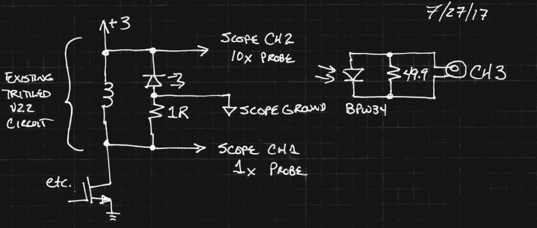
07/27/2017 at 19:40 • 0 commentsI found some time to "follow the energy" in the V2.2 design using a PCB designed just for testing. The interesting addition to the circuit is a 1-ohm resistor in series with the LED:
![]()
The resistor allows the LED current waveform to be captured on the scope. A second channel captures the voltage across the LED, while a BPW34 photodiode near the LED monitors the actual light output. The 50-ohm shunt resistance is important to speed the response of the photodiode. Note the unusual connection of the scope ground - this requires a floating scope, in this case created by running the TritiLED from a 12V battery and an LM317 adjustable regulator to supply 3.00 V.
The resistor does waste a small amount of power (calculated below), but doesn't affect the results very much.
The signal from the BPW34 is not calibrated, but is just used for triggering and to see exactly when the LED is emitting - this resolved the question of whether the LED actually emits any light during the ringing after the pulse. It doesn't.
All measurements were taken with 3.00V supply and a 2-pulse program from the GitHub source code. The inductor has a 30% tolerance, so these measurements should be considered "typical" in the datasheet sense - meaning I saw this once in the lab :-)
I measured the current consumption at 13.54 uA without the scope connected. This increases to 13.96 uA with the probes connected. I don't know exactly how to treat this difference, so I have expressed the efficiency estimates in a range below, assuming one or the other current as a reference.
Here are the waveforms from the three channels. You can see the two pulses that happen at a nominal 62.5 Hz:
![]()
The top (yellow) trace is the LED current (1mV = 1mA). The peak is about 19.8 mA. The middle (cyan) trace is the voltage across the led: note that this voltage is inverted, so the LED is lit on the "low" section of the trace. The bottom (magenta) trace is the light detected by the BPW34.
Efficiency Calculations
Below, I compare the power dissipated by various components to either 3V * 13.54 uA = 40.6 uW or 3V * 13.96 uA = 41.9 uW.
Please make sure these calculations all make sense. They went pretty quickly, so I may have missed something.
PIC Power Consumption
I modified one line in the assembly code so that the PIC clears the MOSFET gate line instead of setting it. This prevents the LED pulse, and results in a current drain of 2.95 uA, or 3V*2.95uA = 8.9 uW. This means the PIC is consuming between 8.9/41.9 = 21 % and 8.9/40.6 = 22% of the power. This bounds the overall efficiency of the circuit to around 78% maximum.
This also means that even if you succeed in driving the oscillator current to *zero*, you can only improve the run-time (or brightness) by 22/78 = 28%. So instead of a 2.5 year light, you get a 3.2-year light. Probably not worth increasing the cost to do, but sure, I'll take 28% more of anything.
End-to-end Electrical Efficiency
I downloaded the waveforms as a CSV file and used octave to numerically integrate the power going into the LED. The LED gets 123.38 pulses of 23.7 nJ each per second for an average power of 29.2 uW. This is between 29.2/41.9 = 69.7% and 29.2/40.6 = 71.9% overall electrical efficiency. Call it 70%. This is in-line with the 78% bound based on the PIC consumption.
Overall, 70% doesn't seem too bad. You see optimized DC-DC converters at 95% sometimes under ideal conditions, but for such a simple circuit, it seems OK. You're not going to be able to double the run-time again.
Current-sense Resistor
A similar numerical integration of I^2R in octave shows that the sense resistor is consuming 0.37% of the power. That's in the noise as far as this rough analysis is concerned.
What's more interesting is this gives us a way to estimate the loss due to the (nominal) 5-ohm resistance in the inductor. Since the inductor wastes energy during both the charge and discharge parts of the pulse, there's a factor of 2x as well as the 5x more resistance, so the loss is roughly 3.7% of the total power.
I had been thinking that the lousy inductor was hurting efficiency, but the PIC wastes about 6x as much.
Bean Counting
So, the PIC uses 22%, the LED 70%, the inductor and sense resistor together another 4%, totaling 96%. The 100R protection resistor consumes less than 0.05%, so there's another 4% going somewhere. I'm willing to accept that as just experimental error in this rough analysis.
Conclusions
The overall efficiency seems OK at 70%. If this were a commercial product, I'm sure it would have been out the door already (assuming the cost was OK). To tweak it further, the oscillator (currently PIC) is the best thing to work on, followed not very closely by the inductor.
The V1.0 was around 39% efficient, so V2.x went in the right direction.
If you go to 1 pulse per wake-up, the PIC consumes a larger percentage, so the overall efficiency actually goes down as the brightness decreases and the run-time is extended. Increasing to 3 or more pulses will increase overall efficiency as well as brightness, but decrease run-time. I'll do some more measurements and make a model for this.
At this point, reducing size and cost seem more interesting than further increases in efficiency. I'd take a win-win-win, though...
TritiLED
Multi-year always-on LED replacements for gaseous tritium light sources