I've been in contact with Melexis regarding calibration and temperature compensation of the MLX90393. They're evidently rationing their application engineers and suggested I contact DigiKey, where I purchased the eval board. DigiKey immediately put me in touch with one of their engineers, who was very eager to help, but set my expectations that he may not have much more luck with Melexis than I had. We shall see. This calibration issue is keeping me up nights, so I'm charging ahead anyway.
Helmholtz Coil
While the Maxwell coil I wound previously is nifty, its better-known cousin, the Helmholtz coil, is much better documented, and using it eliminates one more variable from the experiment.
@jetty has the excellent #Highly Configurable 3D Printed Helmholtz Coil project, which is a very thorough design in OpenSCAD, but is more geared to larger designs with weaker fields, so I decided to create my own. I'll admit to a little "not invented here" syndrome, but the two applications really are different enough to warrant re-inventing the wheel (coil). Just as an example - @jetty's design as built requires about 600mA of current to produce an Earth-strength field over a large volume, while mine requires about 9mA to do the same in a smaller space. Obtaining the 2 mT fields I'm struggling to get by with would require over 60A of current in the larger design. On the other hand, [jetty's] design is perfect for high-accuracy Earth-strength fields.
Here's a picture of the two coils I made with my design. They're supposed to have 100 turns of 24 gauge wire on each winding.
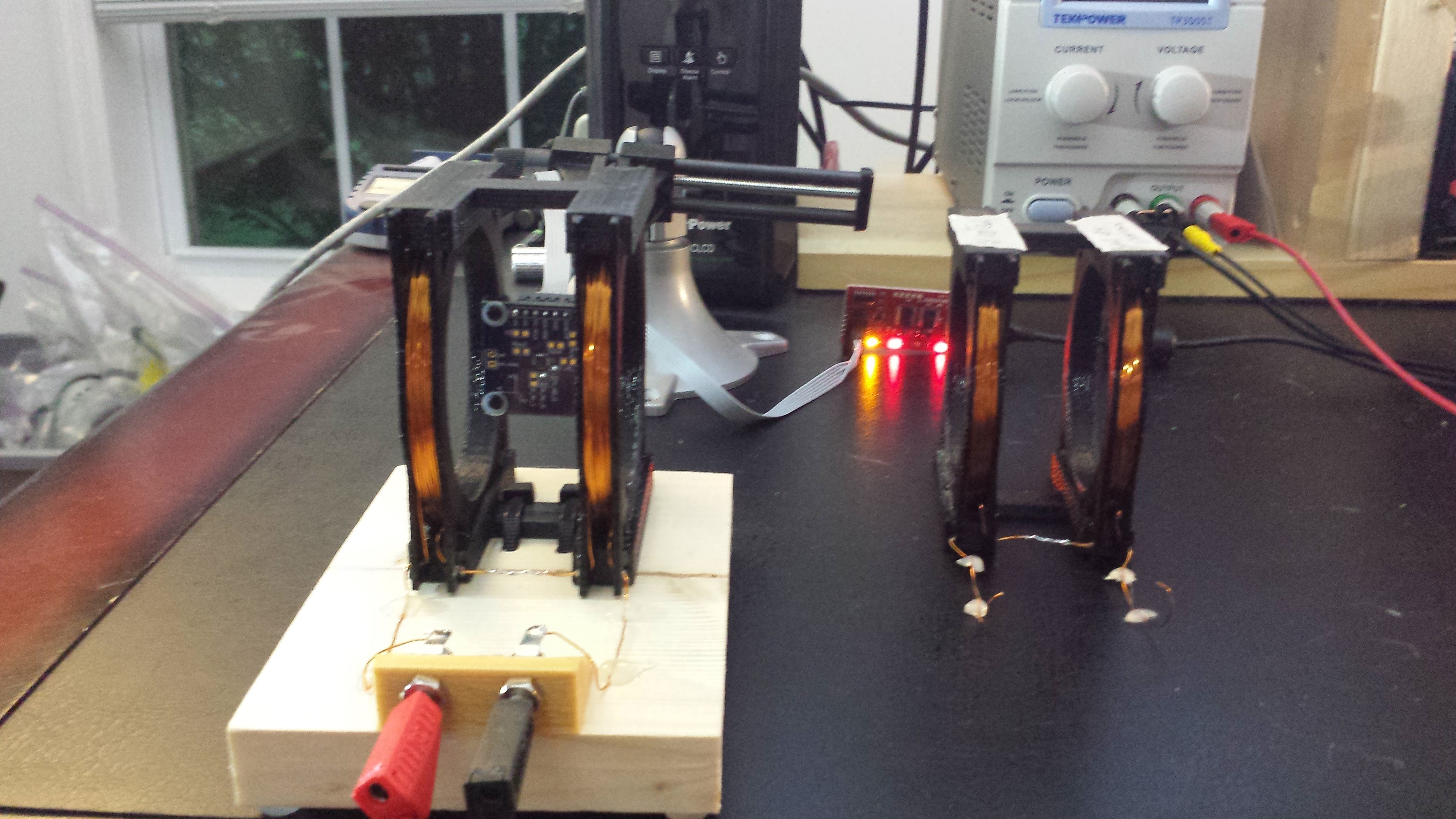
I ended up winding two copies because I got interrupted while wrapping both windings of the first version. I wasn't completely sure if there were exactly 100 turns of wire on either one, so I tested them. My HP3478A meter read 2.173 and 2.223 ohms for the coil resistances, which is troubling. On the other hand, using resistance to evaluate number of turns is problematic - even using 4-wire resistance measurement - since the lead length on the windings is on the order of the length of a turn. I finally measured the inductance of the windings, which is proportional to the square of the number of turns, and relatively insensitive to lead length, so provides a much better measure. Sure enough, the coils read out at 1.524 mH and 1.622 mH, pretty conclusive that the windings are different.
For the second version, I used a python program to count the turns as I very carefully wound them. These windings measured 2.147 and 2.138 ohms and 1.539 and 1.533mH, respectively. I am confident that this coil has exactly 100 turns on each winding.
Analysis
There is a potential problem with this design. The analysis most commonly seen for the Helmholtz coil assumes single conductors in each winding - which is a good approximation for coils like @jetty's, with "small" windings. My design has sizeable windings, however - how much does that complicate matters? I decided to model the "large" windings to find out. I model the "large" windings with m layers of n turns each in a rectangular geometry as shown in the diagram:
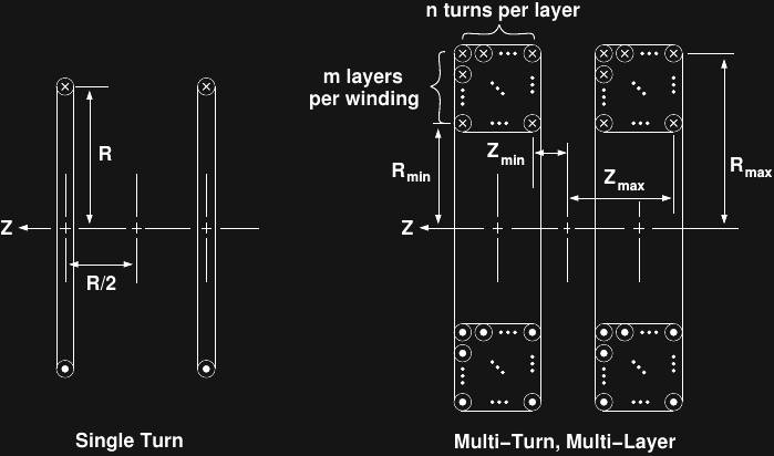
I used wxMaxima again to derive formulas for the field. Starting with the equation for the on-axis field for a single turn:
I first re-derived the formula for the single-turn model:
/* axial field component for a single turn coil of radius R
   carrying current I at distance z */
B_z : \mu[0] * I * R^2 / (2 * (R^2 + z ^2)^(3/2));
/* check that this method produces known formula for single-turn version */
ev(2 * B_z, z = R/2);
Which yields the well-known result:
To evaluate this approximation for the larger-windings, I measured the as-built dimensions and used mean values for the radius and distance:
/* parameters of Helmholtz windings, measured as-built */
z_min : 34e-3/2   /* inner edge of winding */;
z_max : 47e-3/2   /* outer edge of winding */;
R_min : 75e-3/2 /* inner radius of winding */;
R_max : 88e-3/2 /* outer radius of winding */;
n : 10          /* turns per layer */;
m : 10          /* layers per winding */;
/* thin-coil approximation for mean dimensions */
float(2 * 100 * ev(B_z, R = (R_min + R_max)/2,
                        z = (z_min + z_max)/2,
                        \mu[0] = 0.4 * %pi));
Which yields the formula:wxMaxima is just as happy to evaluate the 200-term expression for the multi-turn coil model:
/* sum over layers, turns to get total field */
B_tot :
  2 * sum(
          ev(sum(ev(B_z,
                    R = R_min + (R_max - R_min) * (i-1) / (m-1)), i, 1, m),
          z = z_min + (z_max - z_min) * (j-1) / (n-1)), j, 1, n);
giving:
The error in using the single turn formula for this coil is only .05%! Of course, this analysis doesn't address the uniformity of the field within the coil. For a small sensor near the center of the coil, however, I'm satisfied that the coil construction itself isn't introducing a lot of error.
Tangent Magnetometer Test
I read in #Highly Configurable 3D Printed Helmholtz Coil about using the coil and a compass to measure the Earth's magnetic field, then also found this paper describing a similar method, and decided to use the Earth's field to sanity check my coil and calculations.
Using the NOAA's magnetic field estimator, I plugged in my GPS coordinates to obtain (x, y) field values of (19.036 +/- 0.138, 4.604 +/- 0.089) μT, for a total field in the x-y plane of 19.585 +/- 0.164 μT. This is around a 0.8% error bound.
Using the voltage and resistance standards I have available (0.1% and 0.05%, respectively), I measured a calibration for my DMM on the current setting. The uncalibrated error was around 0.3%.
I found a spot in the front yard away from any metal structures to set up the experiment:
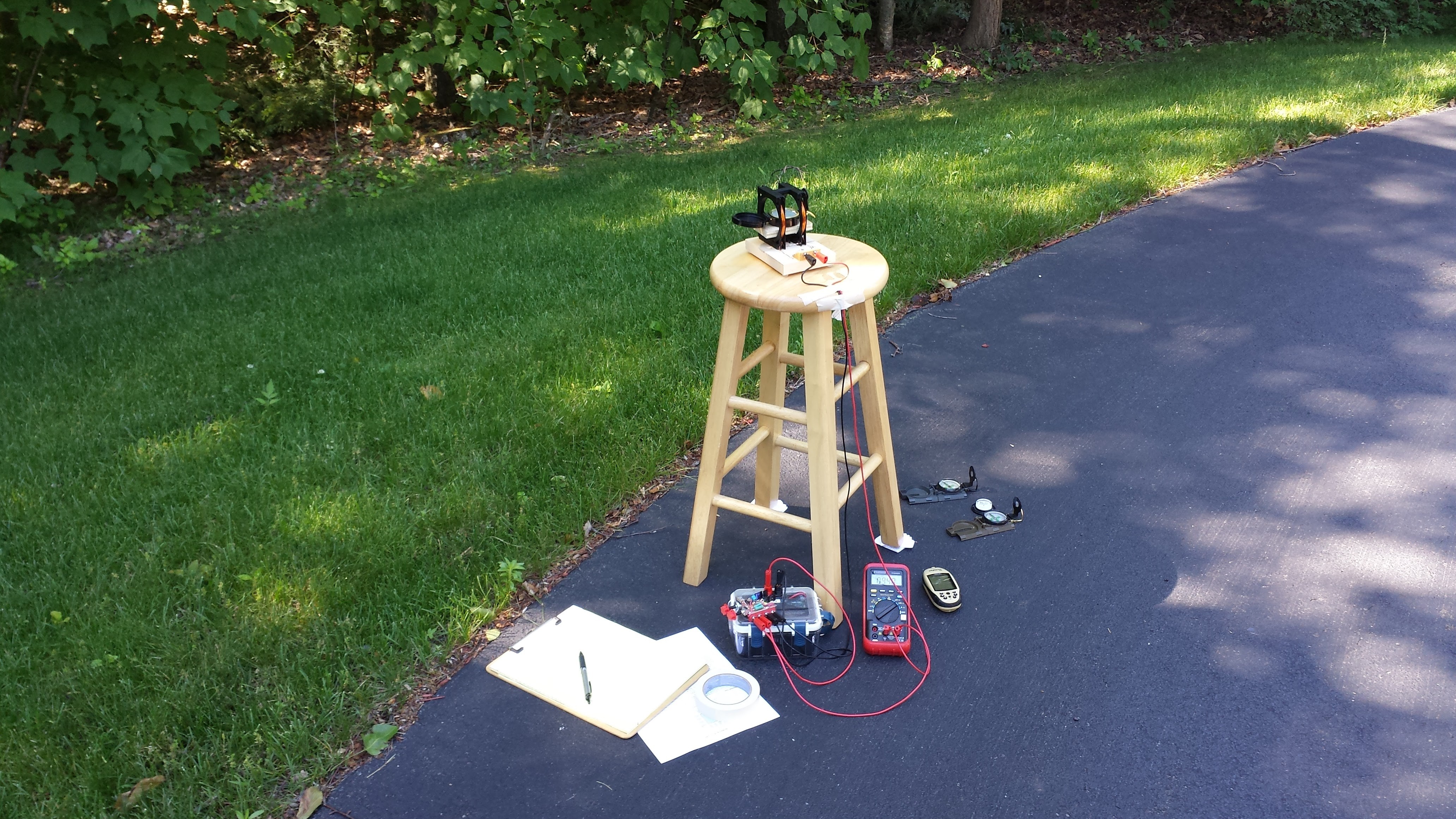
The only compasses I had were really too large relative to the coil, but until some smaller ones arrive, this will have to do. I carefully levelled the platform, since the vertical component of the field at this location is 2.5x that of the horizontal. When the coil is aligned east-west, the ratio of the coil's field to the Earth's is related to the needle's deflection angle by:
I measured the needle deflection for a series of coil currents, and used the known geomagnetic field to calculate the coil field from this equation. Here's the plot of the estimated field for each current:
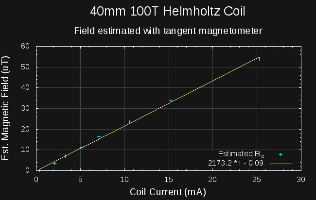
Ignoring the tiny additive constant, the best-fit line reveals an expression for the measured coil field:
This value (2173) is only about 1.8% smaller than the constant calculated from first principles above. I haven't done a thorough uncertainty analysis, but at first glance, it looks like the coil is working as designed, and the field values are probably accurate to a few percent.
MLX90393 Measurements (again!)
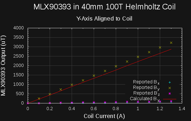
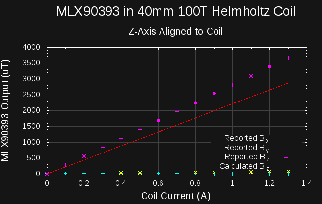
Armed with a validated coil, I measured the 3-component field vectors for the MLX90393 aligned in the coil on each axis:

|
|
|
Using the calculated factor (2213.6) for the Helmholtz coil, and fitting regression lines to the MLX90393 outputs vs calculated field values gives the following scale constants:
| x-axis | y-axis | z-axis |
| 1/1.098 | 1/1.117 | 1/1.273 |
so, the field values reported by the MLX90393 are off by around 10-11% in x and y, and almost 30% in z
You can see, especially in the y-axis plot, that I didn't manage to get the axes precisely aligned; there's some spill of the field into the supposedly orthogonal axes (the MLX90393 lists additional 1% typical cross-sensitivites). Correcting for this isn't trivial, since we don't know the scale factors a priori: if we did, we could just calculate the total field and regress to that. Instead, I just roughly estimated the error using the uncorrected raw values, obtaining bounds of around 0.2% for x, 3.4% for y, and 2.2% for z.
I'll work through the math to come up with a better method for dealing with this error.
The conclusion seems to be that the MLX90393 sensor will need calibration in the scanner. I'm thinking of a small 3-axis coil that can serve double-duty: calibrating the field range of the 3-axes, and aligning the magnetic field vectors in the printer's coordinate system. I haven't discussed the latter issue much, but I've given it a lot of thought, and this seems like the easiest way to get the magnetic coordinate system properly registered with the spatial one.
Next Up
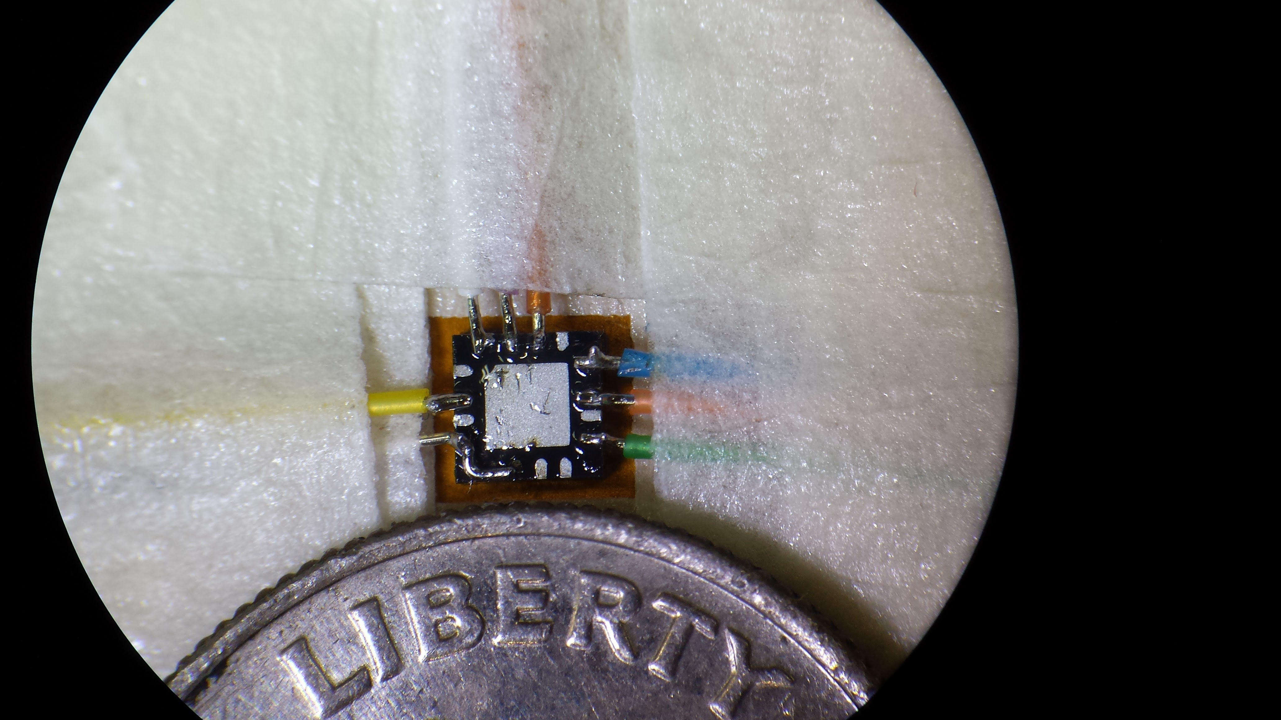
Sleep. It's 02:30 local time. Tomorrow, I'll try out this assembly. I couldn't wait for boards, so I soldered wire-wrap leads to the 3x3mm QFN package directly:
 Ted Yapo
Discussions
Become a Hackaday.io Member
Create an account to leave a comment. Already have an account? Log In.
This is great work! Can I ask what your low-profile breakout for the MLX90393 looks like? I've been looking for somewhere that will do small runs of flex PCBs that I could stick an MLX90393 at the end of, but the cost is prohibitively expensive... It might just end up having to be a normal FR4 board that's just very narrow...
Are you sure? yes | no
I uploaded a zip file with the current board ideas. They're just quick sketches, really, that I was able to throw together in a few spare minutes I had last week. There's an Eagle library with an MLX90393 footprint in there, too - untested, but you might find it useful.
https://cdn.hackaday.io/files/11865507632160/board_sketch.zip
Are you sure? yes | no