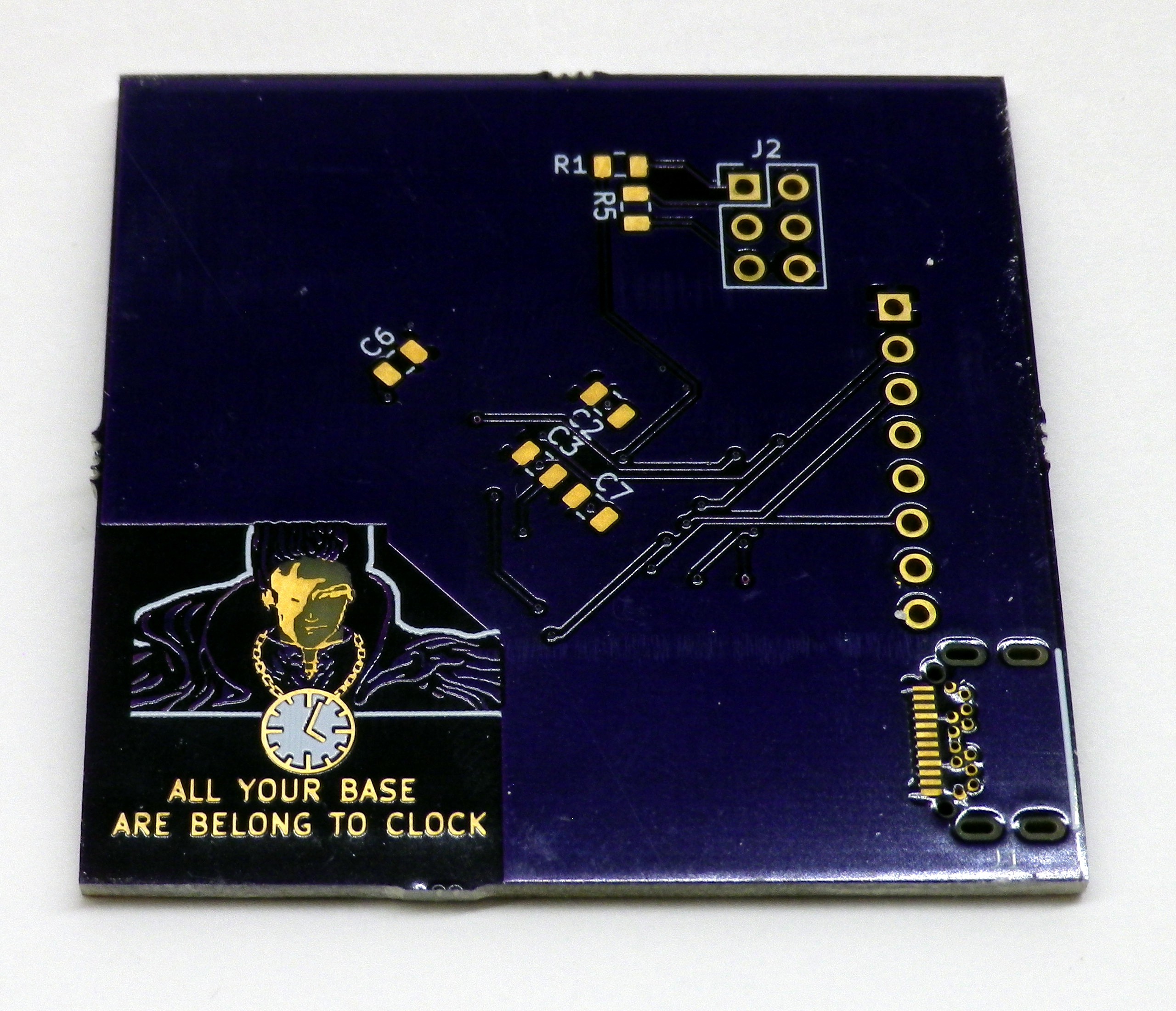
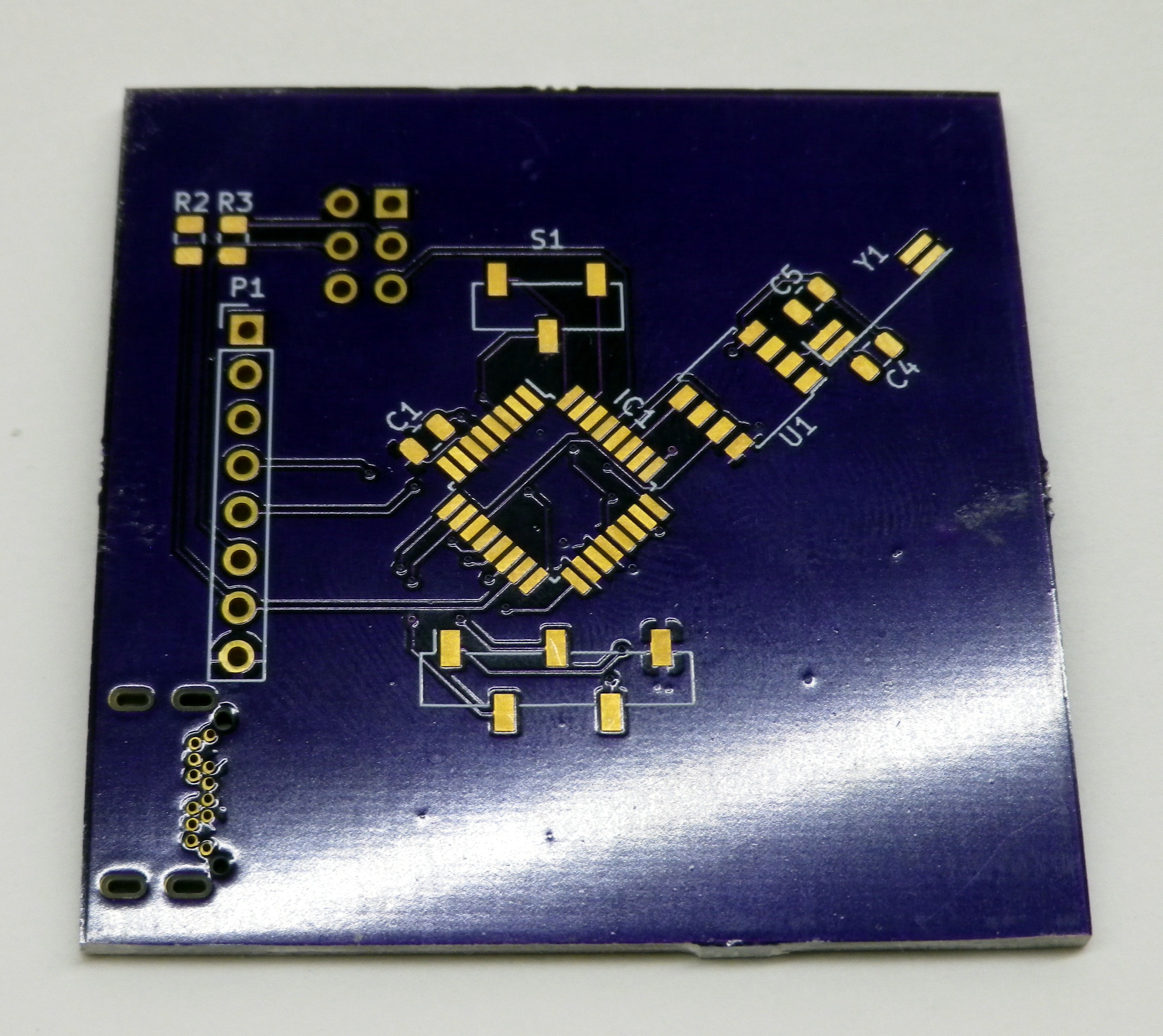
After almost 5 years from the first starting post the "All Your Base Are Belong to Clock" clock is finally in a completed state. To finish off the final touches I put together a PCB for the control board (found on github), updated the code (also on github), finished up the final parts of the frame (via help of my woodworking friend Kyle) and assembled all the parts together. Pictures of the final assembly displaying the time in various bases can be found in the project gallery.
Control Board:
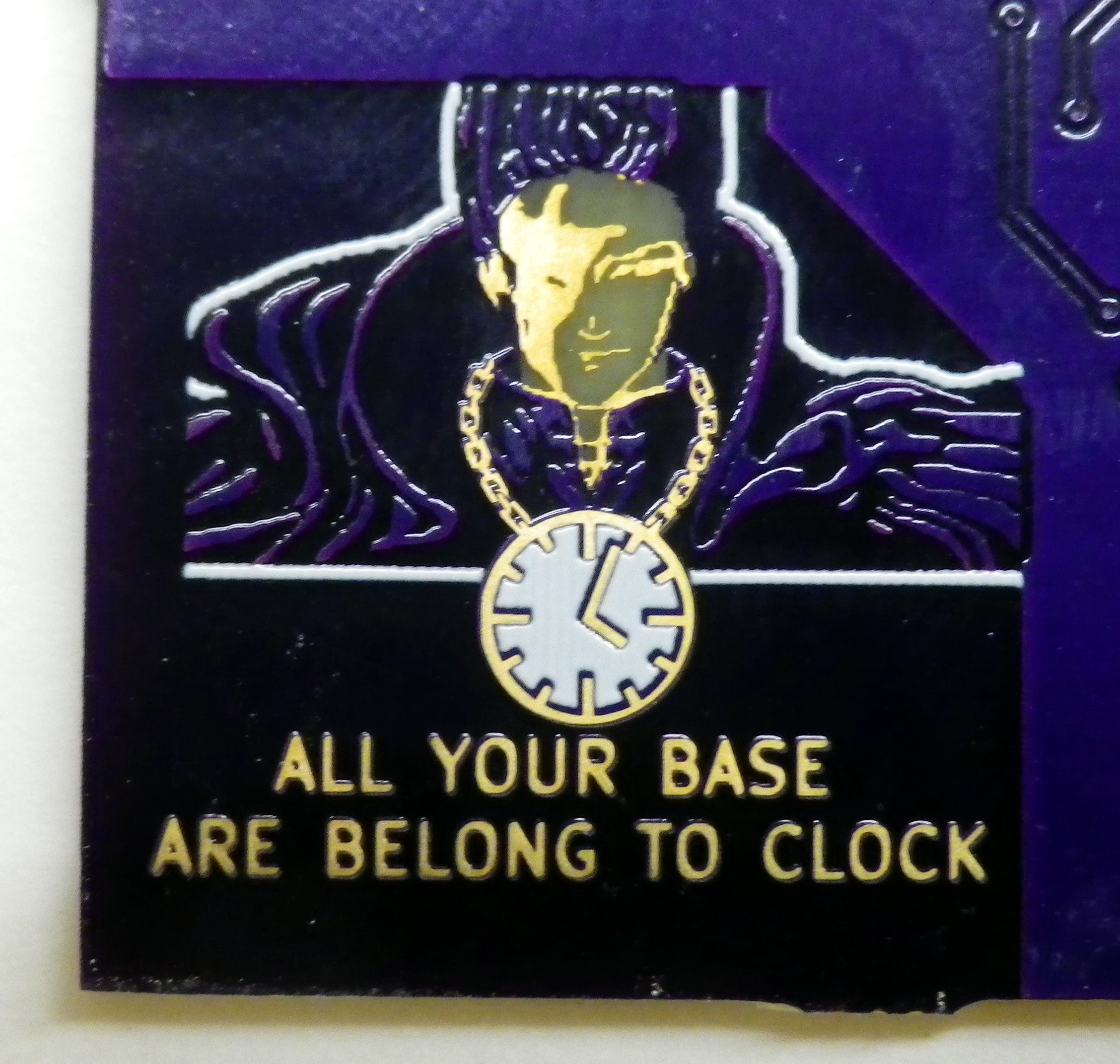
The control board contains the mega328 controller, clock IC, programming header and USB-C connector for power (USB-C selected for the reversibility of the connector and it seemed fun to try something flashy and new). Because the size of the control board was based on the size of the segment boards and the extra width left in the frame there was extra room for some fun PCB art. The image was generated using GIMP convert the image into 5 colors (solder mask + copper, solder mask - copper, exposed copper, bare PCB [no solder mask or copper] and silkscreen). The colors were then combined into three separate images, one where the copper is, where the solder mask isn't and where the silkscreen goes. The resulting images were imported into Kicad using the import bitmap feature to generate the sweet PCB art below.


Code Updates:
Features added to the code:
- Display of the current base
- Randomly change the base every 0(off) to 60 minutes
- Set the upper and lower bounds for the random base selection
- Adjust the yellow balance point
- Configure the color of the encoder to various settings:
- Current second, minutes or hour value
- Current base
- Randomly change every 5 seconds
- Continuous color cycle
- off
A side note on random number generation and seed initialization. Because random numbers are used relatively infrequently in the project (at most once every 5 seconds) I'm using the C standard lib rand() to generate numbers instead of some hand crafted rand() function optimized for generating 8 bit values that I need. In order to see the random number generated I have a counter that is running from the initial boot and at the first detected rotation of the encoder the random number generator is seeded with the counter value. Because no random numbers are used unless non default settings are used there will always be rotations of the encoder to ensure that the RNG is seeded with a value that is probably different than a previous iteration which generates random enough for my purposes.
Frame Finishing:
The frame was given a few coats of stain and had the top and front edges rounded off. The pieces are held together using brass screws to give a similar dark/gold colored aesthetic that the PCBs have. A metal plate painted black was installed on the front of the control board to help hold the board in place and give a nicer finished look. A fender washer was used to give a little reflection for the light from the encoder.
Final Thoughts:
Even though this project dragged on much longer than it should have I'm really happy with how things turned out. The segments look a bit nicer in real life than they do in the pictures and the frame gives it a nice finished feel to it. This was also my first project to mess around with PCB art and I'm happy with how that turned out.
 Gorloth
Discussions
Become a Hackaday.io Member
Create an account to leave a comment. Already have an account? Log In.