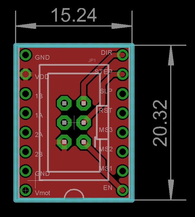
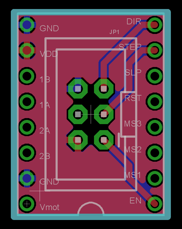
here are two parts to this project: a board that takes the step, direction, and enable pins from a socket meant for an A4988 stepper motor driver, and a second board that fans it out to four separate A4988 motor drivers.
Here's the cable adapter:
Simple enough, and uses very common 2x3 ribbon connectors.
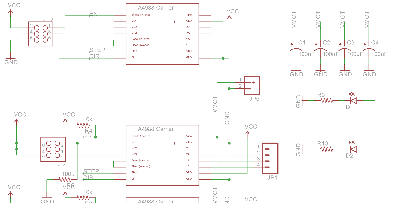
The second board drives four A4988 motor controllers with all the requisite hardware. These boards are combined into a single PCB for ease of ordering.
It's designed to connect to stepper motors and a power supply through screw connectors.
And the relevant parts of the schematic:
 Benchoff


Discussions
Become a Hackaday.io Member
Create an account to leave a comment. Already have an account? Log In.