Close
0%
0%

A4988 Stepper Driver Duplicator

Putting two steppers on a single driver is dumb. Four doubly so. Here's a stepper driver breakout.

Similar projects worth following
Turns one stepper motor output into four.

What do you do when you need to drive multiple stepper motors with the same step, direction, and enable pins? If you're in RepRap land, you just connect two steppers to the same output. This is dumb.

I have a project that needs to drive four steppers for the Z axis of a printer. The easiest solution? Break out the Step, Direction, and Enable pins on an A4988 socket to four different motor drivers. This is the project that does the job.

License:

            DO WHAT THE FUCK YOU WANT TO PUBLIC LICENSE
                    Version 2, December 2004

 Copyright (C) 2004 Sam Hocevar <sam@hocevar.net>

 Everyone is permitted to copy and distribute verbatim or modified
 copies of this license document, and changing it is allowed as long
 as the name is changed.

            DO WHAT THE FUCK YOU WANT TO PUBLIC LICENSE
   TERMS AND CONDITIONS FOR COPYING, DISTRIBUTION AND MODIFICATION

  0. You just DO WHAT THE FUCK YOU WANT TO.

license.txt

plain - 498.00 bytes - 06/30/2016 at 16:42

Download

StepperBreakout.sch

sch - 170.83 kB - 06/30/2016 at 16:30

Download

StepperBreakout.brd

brd - 77.46 kB - 06/30/2016 at 16:30

Download

  • 4 × A4988 Stepper motor driver
  • 4 × SMD 100uF Electrolitic EEE-1HA101UP / Digikey pn: PCE3917CT-ND
  • 1 × Headers, pins, and connectors A bunch

  • Boards Get

    Benchoff06/25/2016 at 20:26 1 comment

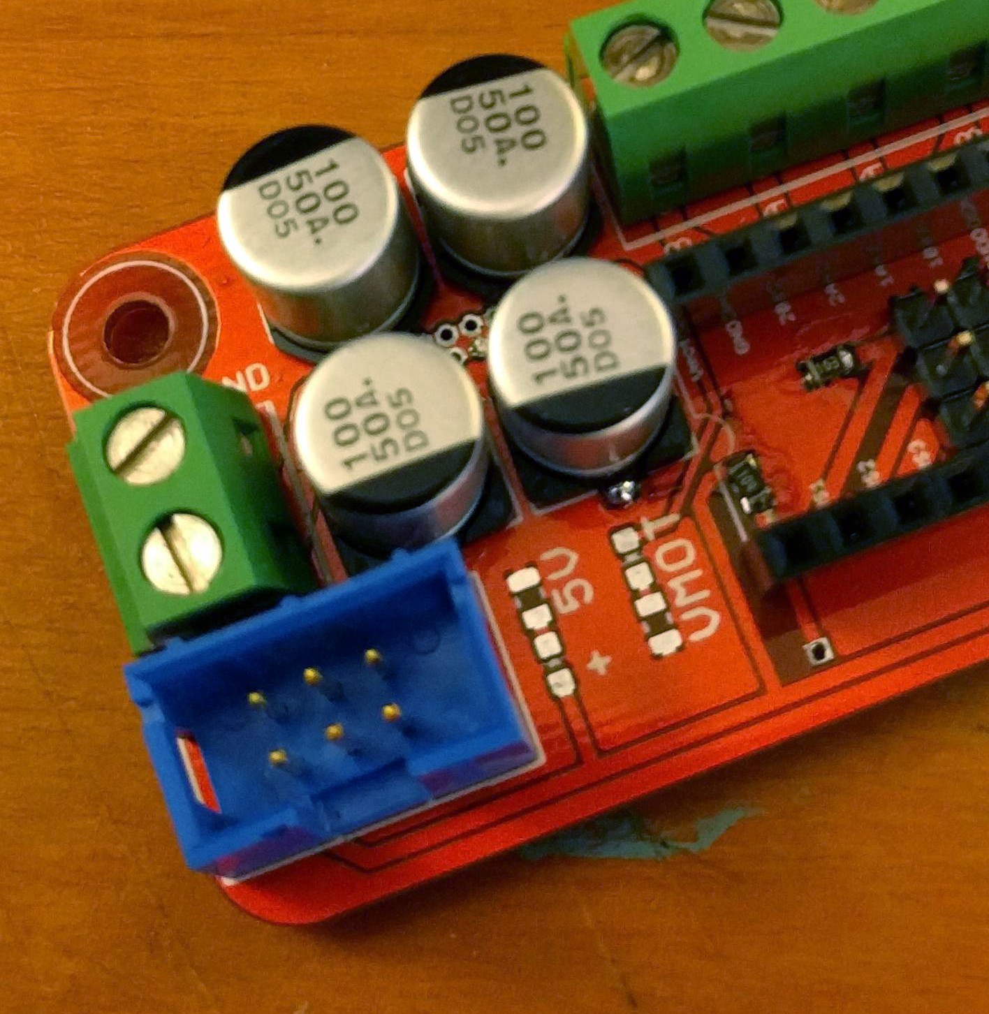
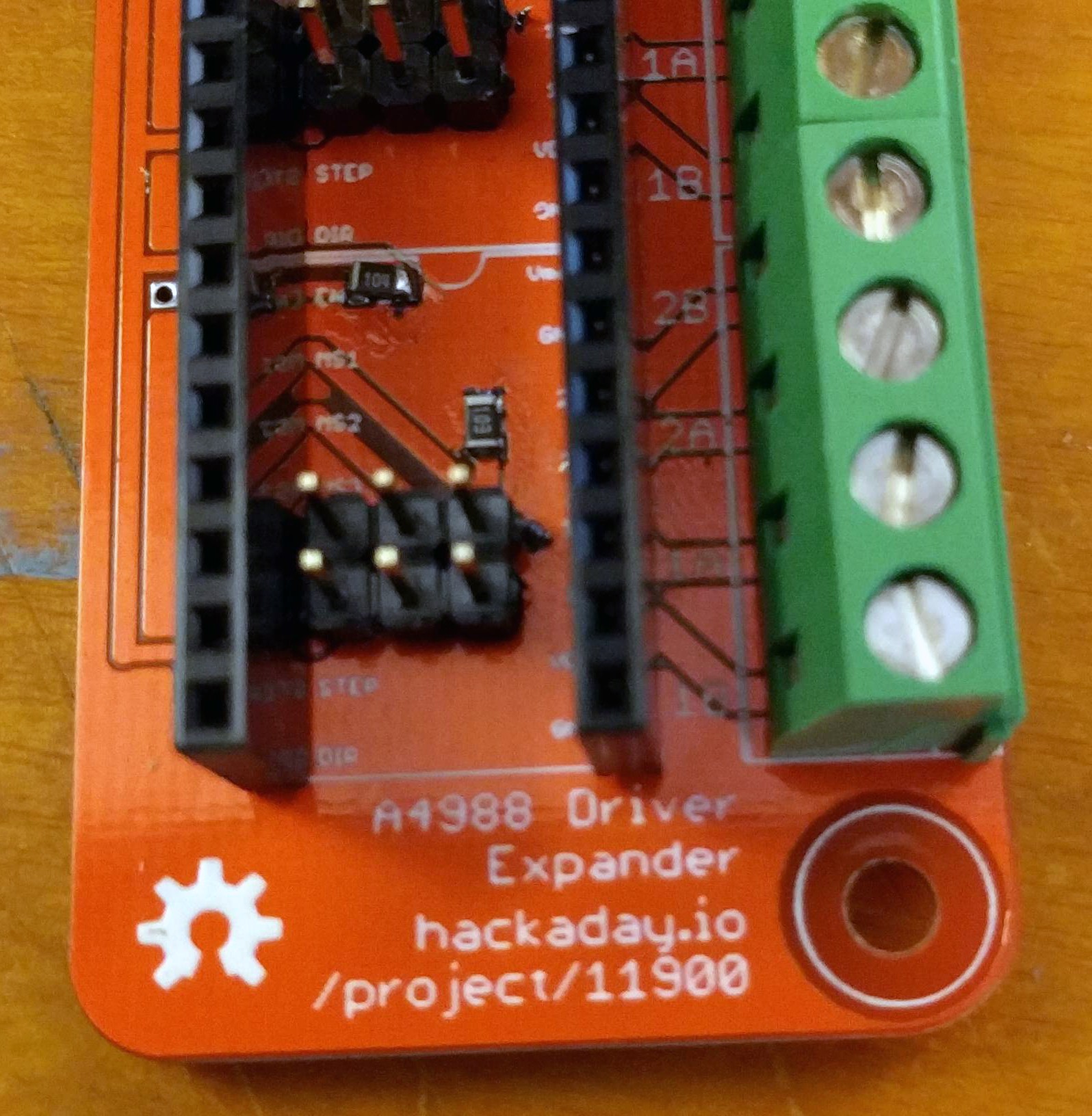
    Got the boards from Seeed yesterday, and soldered one up:

    Assembly was easy. I was worried about soldering the SMD caps, but with the right tip it was simple enough.

    Right now, this project is *done*, but I still need to test it. That's not going to happen until I have the Z motors in the Long D printer, and that won't happen until some weird flanged bearings show up in my mailbox.

    I have 9 more of these boards. If you want one, drop me a line and I'll see what I can do. Otherwise, I'll just give them all away at next year's MRRF.

  • Implementation

    Benchoff05/26/2016 at 14:27 0 comments

    here are two parts to this project: a board that takes the step, direction, and enable pins from a socket meant for an A4988 stepper motor driver, and a second board that fans it out to four separate A4988 motor drivers.

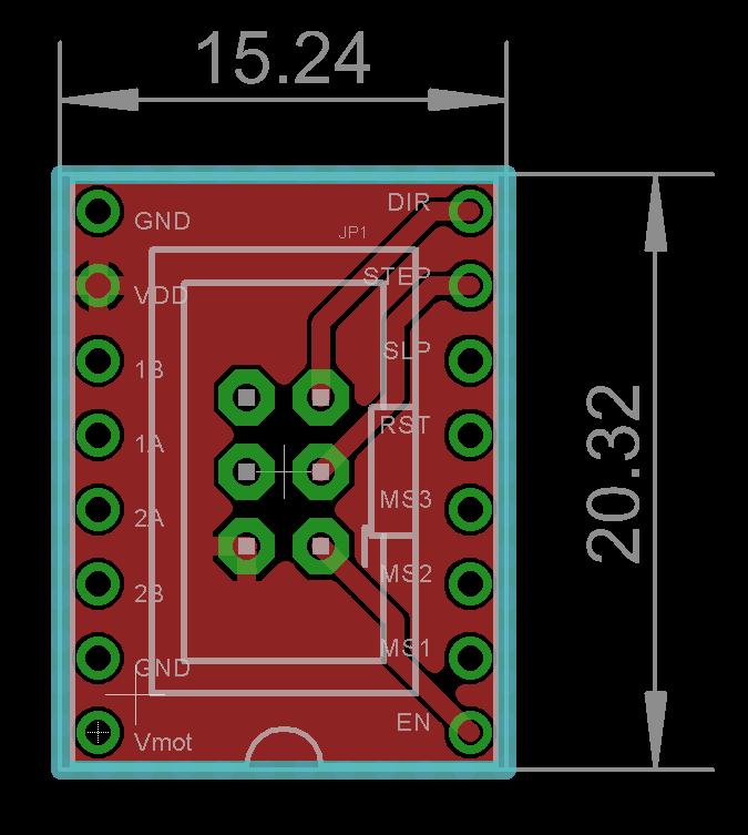
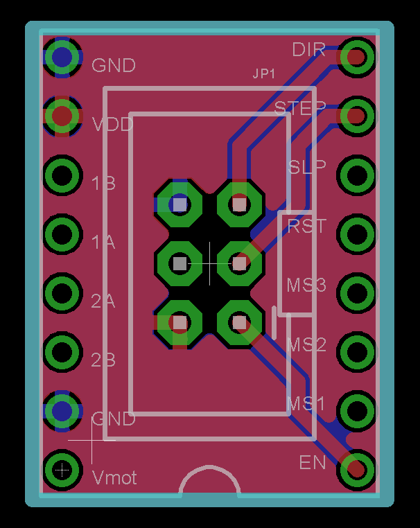
    Here's the cable adapter:

    Simple enough, and uses very common 2x3 ribbon connectors.

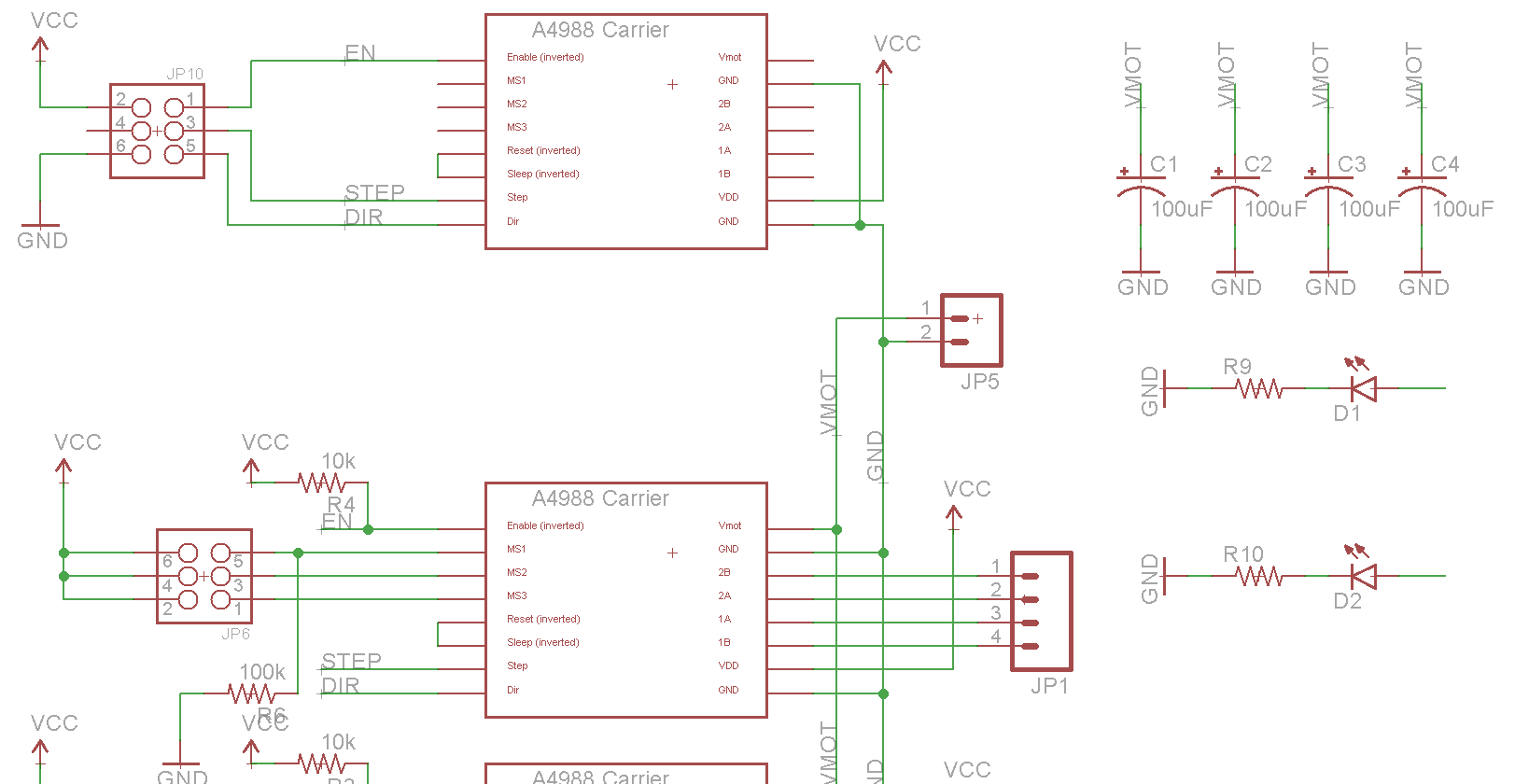
    The second board drives four A4988 motor controllers with all the requisite hardware. These boards are combined into a single PCB for ease of ordering.

    It's designed to connect to stepper motors and a power supply through screw connectors.

    And the relevant parts of the schematic:

View all 2 project logs

Enjoy this project?

Share

Discussions

Carter Brown wrote 09/27/2020 at 01:47 point

If you think it is troublesome to DIY or purchase components. Recommend a website-MOTIONGOO that sells A4988 and A4988 socket (expansion board).

The price/performance ratio is particularly good. And the stepping motors connected to the A4988 socket can be independently controlled.
A4988:
https://www.motiongoo.com/a4988-stepper-motor-driver-module-heat-sink
A4988 socket (expansion board):
https://www.motiongoo.com/engraver-shield-expansion-board-3d-printer-cnc-v3

  Are you sure? yes | no

warhawk-avg wrote 09/13/2017 at 03:31 point

Can we get a 2 version of this please? ;)

So it will be little bit cheaper from the fab house?

  Are you sure? yes | no

Benchoff wrote 09/13/2017 at 03:46 point

It's really as cheap as it's going to get.

  Are you sure? yes | no

warhawk-avg wrote 07/01/2016 at 03:15 point

Brilliant!  Now just need to cut one down to a dual driver for the majority of Z-axis 3d printers that use dual motors (or as others say get a RAMPS 1.4 board that has up to 5 A4988 sockets on the board), I like how your build gives people the ability to increase powered steppers vs just a wiring splitter board that either cuts the volts or the current depending on series or parallel wired.  Your build allows for synchronized powered operation at full volts/current without needing to upgrade the main controller board...way way cool!

  Are you sure? yes | no

AVR wrote 06/09/2016 at 22:27 point

why not integrate the contents of the stepper driver PCBs and your custom PCB together, you can get a more optimal layout for cooling the driver and ensure you can deliver max current per phase. 

  Are you sure? yes | no

Benchoff wrote 06/10/2016 at 00:03 point

Because that's more work.

  Are you sure? yes | no

warhawk-avg wrote 06/01/2016 at 20:13 point

You have a ground plane on the top side, in order to be able to push more current to the drivers (will that trace be able to handle a combined total of 8A to Vmot pins?)
I tweaked yours a wee bit (if you don't mind)...added multiple vias in the trace on the capacitors, created a Vmot plane on the back side, and did a few cosmetic tweaks.

Here is the link to what I did

https://www.dropbox.com/sh/yyo1lx09gwep4y0/AAC9s4SgjpFAOaqdHAVO9No2a?dl=0

  Are you sure? yes | no

Benchoff wrote 06/03/2016 at 17:44 point

Excellent idea. 

I updated the board file and sent the new one off to seeed. 

  Are you sure? yes | no

Similar Projects

Does this project spark your interest?

Become a member to follow this project and never miss any updates