Close
0%
0%

RelayRepRap

This project is about exploring whether it is possible to make a RepRap control system that can be made by a RepRap.

Similar projects worth following
The RepRap project has two parallel, overlapping aims - one is to make readily accessible low-cost 3D printers, the other is to make self-replicating 3D printers. The project was able to achieve the first goal because a RepRap is able to make many of its own mechanical parts: structural elements, gears, springs etc...

I'm interested in RepRap because I'm interested in self-replicating programmable constructors - machines that can construct other machines, and which can construct themselves.

A difficulty in making a more completely self-replicating RepRap is the control system. RepRaps are controlled by microcontrollers, and microcontrollers are made by a complex process in expensive semiconductor fabrication plants.

I'm investigating whether a RepRap control system can be built using relays made from RepRapped parts and simple easy-to-manufacture vitamin parts. My motivation for the project is largely curiosity about whether it can be done.

I've been interested in self-replicating machines since I first read about the idea many years ago.


Often when people talk about the idea of a self-replicating machine what they have in mind is a system that can be programmed to construct other machines, and which is capable of making a duplicate of itself. A system that can only make a duplicate of itself, but nothing else, is a much simpler proposition - examples of this kind of system include fire and a growing crystal.


Making a self-replicating programmable constructing machine is a very difficult problem. The machine must be capable of carrying out all of the materials processing, fabrication and assembly operations required for its own construction, and it must contain all of the information needed to direct these operations.


In the RepRap project, a pragmatic compromise is made whereby the machine can make some of its own parts from plastic feed-stock, but other parts (so-called vitamin parts) are externally supplied. A RepRap depends upon its human operator to assemble all of the parts and calibrate the machine. The RepRap project has been spectacularly successful : low-cost, practical 3D printers now exist in abundance.


It is interesting to consider whether the range and complexity of the vitamin parts that a RepRap requires can be reduced. (So far as the mechanical parts of the machine are concerned, the RepRap Snappy goes a long towards doing this). The most complex of the vitamin parts is the microcontroller. The process of making a microcontroller is very complex. A large number of materials and processing steps are involved. Is it possible to make a RepRap controller using alternative, simple to construct, computing technology?

Some discussions about this took place on the RepRap developer forums a few years ago:

http://forums.reprap.org/read.php?2,102361,103220#msg-103220

http://forums.reprap.org/read.php?2,202918

The RelayRepRap project is about trying to do this using relays. I don't expect that this will result in a machine that will be useful in any way - not in the immediate future at any rate. This project is motivated by curiosity about the scientific question: how close can we get to making a fully self-replicating programmable constructing machine? Trying to make a microcontroller-less RepRap is one way of exploring this question.

By the end of the Hackaday 2016 prize period (October 10 2016), I plan to make a working prototype 2D plotter (i.e. the X and Y axes of a 3D printer) using only the following materials (see project images): enameled copper wire, copper nails, iron nails, solder, aluminium foil, PLA, water, and bicarbonate of soda. I might add other materials to this list if I discover during prototyping/experimenting that they are necessary.

RelayRepRap is covered by the GNU General Public Licence version 3: http://www.gnu.org/licenses/gpl-3.0.en.html. You are free to change and share this work, but in doing so you must make sure that others are free to do the same under the same terms as this license.

controller_explanation.pdf

This PDF shows a plan for a relay-based control system for a 2D plotter, driven by a punched tape. The plan has links to videos illustrating some of the ideas, and working implementations of some of the relay circuits.

x-pdf - 42.63 kB - 05/26/2016 at 22:09

Preview

  • Making batteries

    will.stevens05/09/2017 at 17:47 0 comments

    One of the problems that remains to be solved in this project is how to provide electrical power to the system without greatly increasing the range of materials needed for the complete system. Plugging it into the wall wouldn't do, since this would depend upon the electricity generation and distribution infrastructure.

    Homemade batteries seem like a promising alternative. Some batteries are very easy to construct, and will provide a constant voltage.

    Googling homemade batteries and 19th century batteries leads me to believe that two promising alternatives are aluminium-air batteries (https://en.m.wikipedia.org/wiki/Aluminium-air_battery) and batteries using the gravity cell variant of the Daniell cell (https://en.m.wikipedia.org/wiki/Daniell_cell).

    In terms of the simplicity of their construction, and the range of materials used in their construction, there is little to choose between them. The gravity cell requires copper sulphate, which is non-trivial to produce from raw materials. The aluminium-air battery requires activated charcoal, which I believe can be made from charcoal treated with an acid or alkali. I have a slight preference for the aluminium-air battery. I believe that potassium hydroxide solution (an alkali) can be obtained from wood ash, so this is a possible route for the production of activated charcoal.

    Below is a video showing my first attempt to make an aluminium-air battery:

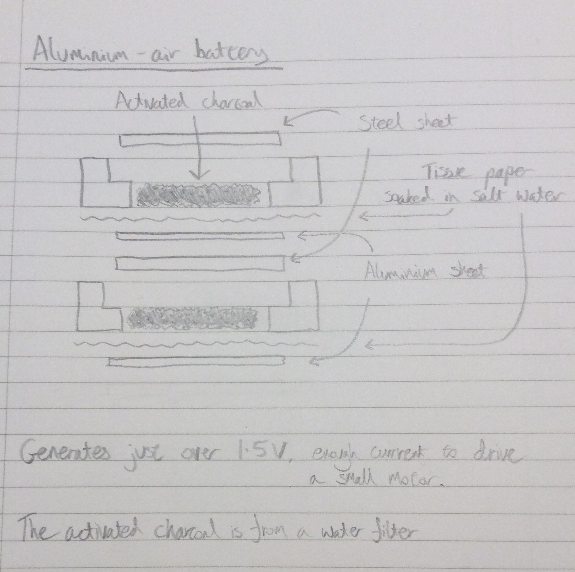
    Here is a diagram showing how the battery is constructed:

    A battery of six of these cells, with a surface area about twice as large as shown in the video, should be able to activate a single relay.

  • A divide by 3 circuit using copper contact relays

    will.stevens04/23/2017 at 08:56 1 comment

    The video below shows relays with copper contacts being used to make a divide by 3 circuit. This is much more successful than my earlier attempt to make the same circuit (part of project log dated 10th Oct 2016). The copper contact relays operate from a lower voltage than my earlier relays, partly because I've become better at assembling them, partly because the new relays only require one nail per contact, whereas previously I had to double-up to compensate for the unreliability of the nail-nail contacts.

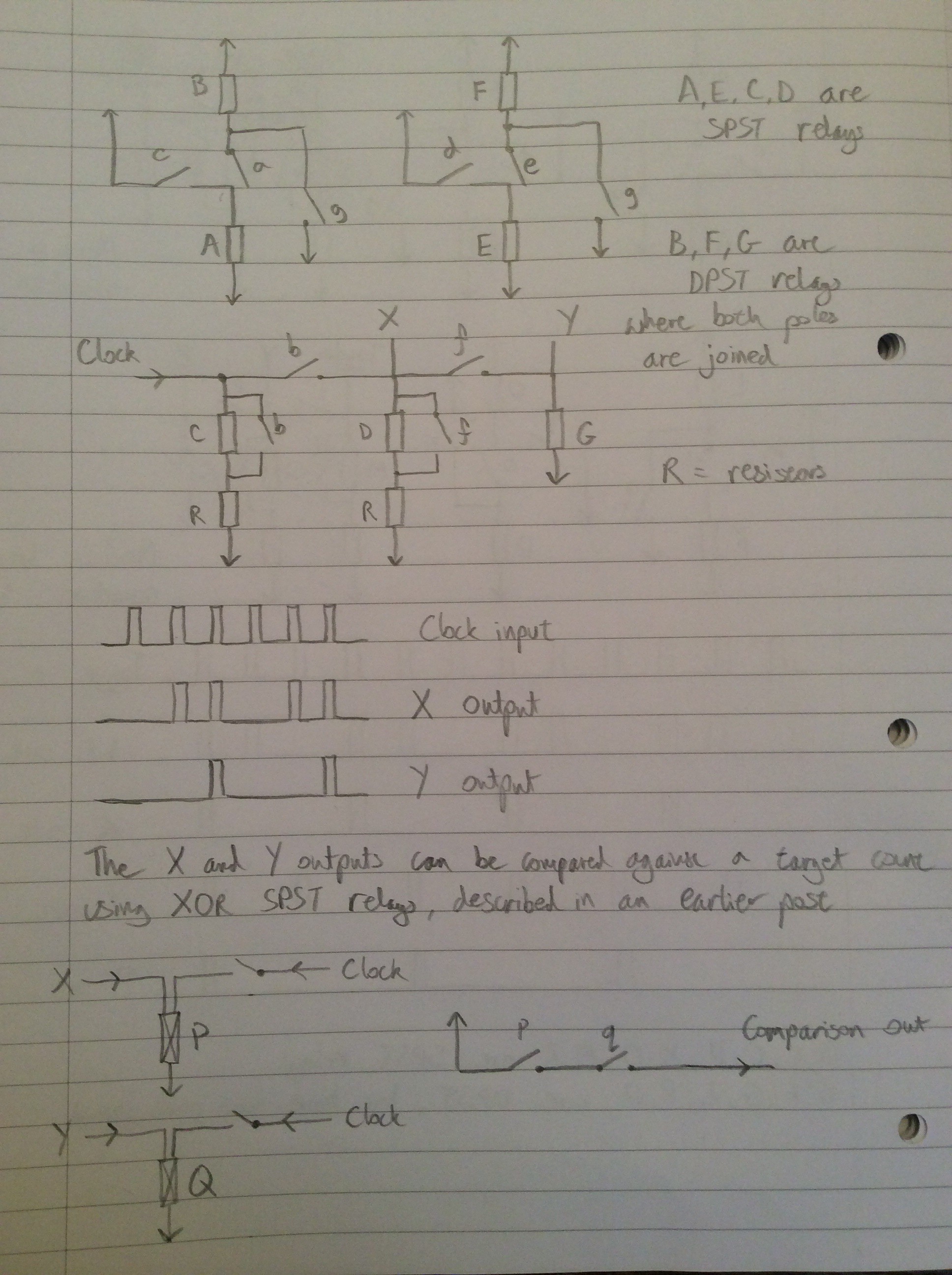
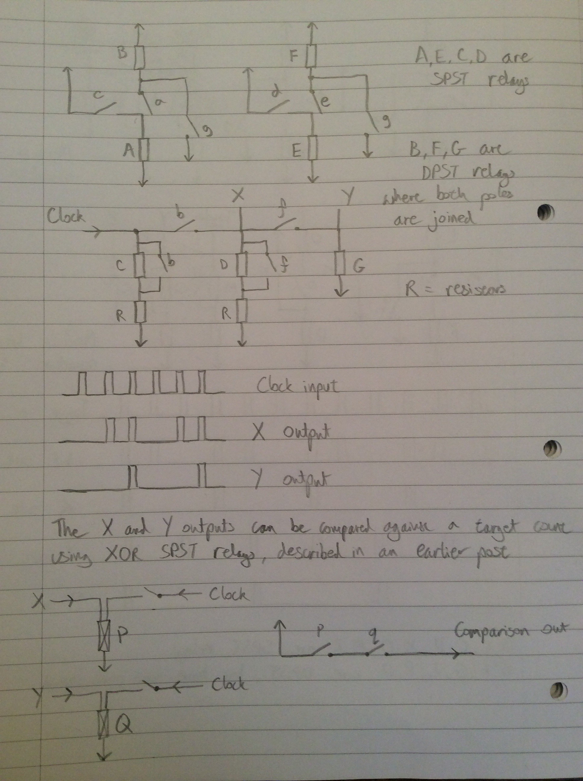
    Below is the circuit diagram, repeated from the 10th Oct 2016 log entry:


    Relays (A,B) behave like a trailing-edge driven set/reset circuit, where C provided the set signal and G provides the reset signal. The contacts of B change state immediately after removal of the set or reset pulse. Relays (E,F) are a similar circuit. The network of relays and resistors involving relays C,D and G route the clock signal to the appropriate place depending on the state of relays B and F.

    E.g. If neither B nor F are active, the clock signal is routed to set (A,B). If B is active but F isn't then the clock is routed to set (E,F). If both B and F are active then the clock is routed to reset both.

    Below is a video of the same circuit stepping a motor on every third clock pulse:

  • An oscillator driving a toggle flip flop

    will.stevens04/14/2017 at 08:26 1 comment

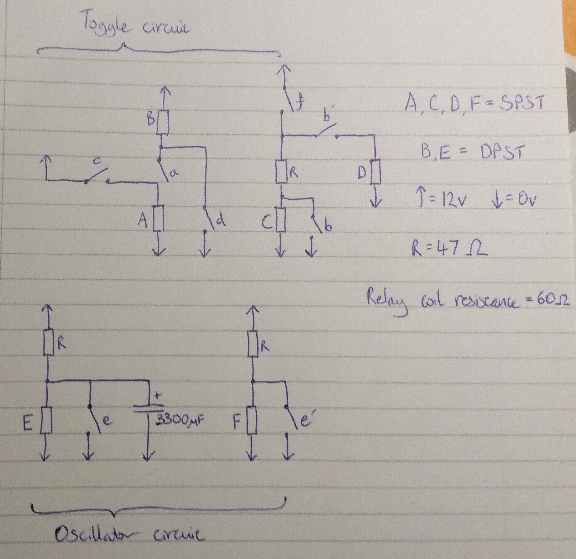
    This video and circuit diagram show an oscillator driving a toggle flip flop. The oscillator is to the right of the video.

    The oscillator uses a capacitor to delay the closing of a relay which, when closed, discharges the capacitor and deactivates the relay, starting the next cycle. A DPST relay is used so that the second pair of contacts can be used to generate a clock signal. Perhaps because the DPST relay has slow contact closure due to gradual charging of the capacitor, I found that it could not be used directly for the clock signal, so a second relay is used to buffer (and also invert) the signal.

    A 3300 microfarad off-the-shelf capacitor is used in the oscillator. I'd like to replace this with a homemade equivalent, or come up with an alternative (possibly mechanical) oscillator design that doesn't require a high value capacitor.

  • Toggle flip flop using new relay

    will.stevens04/02/2017 at 21:43 2 comments

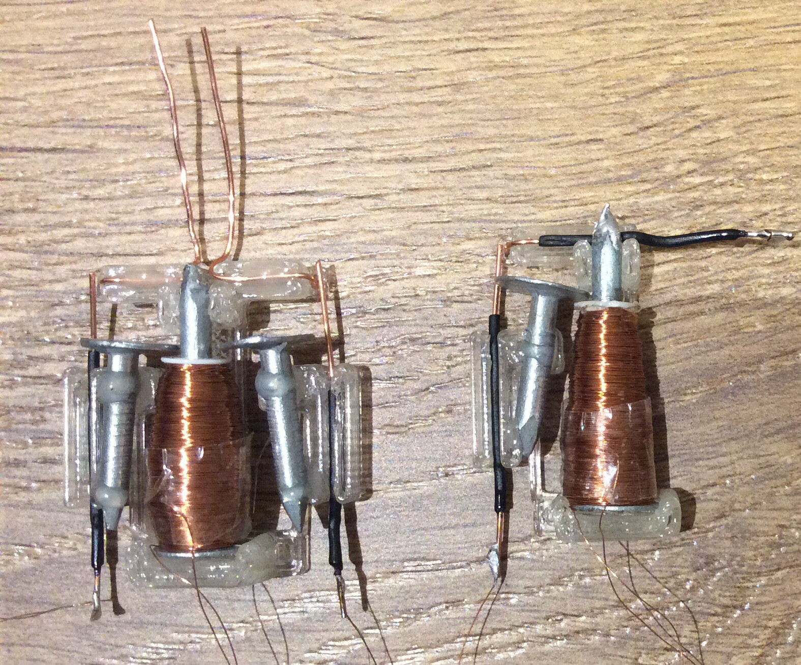
    This video shows a toggle flip flop made from copper contact relays. Initially there was a problem with oscillation of the relay contacts after the relay opens: because the contact separation distance is less than the nail-nail distance, it is possible for the contacts to re-contact after opening as the nail vibrates briefly after the contact opens. Only the DPST relay exhibited this problem, and it was solved by bending a piece of insulated wire in such a way that after opening, a contact hits the wire, damping the oscillation enough to prevent the problem.

    Here is a close-up photo of two of the relays (before the damping solution had been implemented for the DPST relay):

  • Making metal

    will.stevens12/26/2016 at 20:28 1 comment

    I came across some photos earlier today that are relevant to this project. This project involves using as few raw materials as possible, and using raw materials that are as simple as possible. How exactly the simplicity of a raw material should be defined is a difficult question to answer: simple with respect to what? A context must be given.

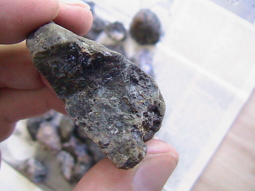
    In the south west of England there are a wide range of natural resources available. There are locations in the southwest where ores of copper, tin, lead and iron can be found within a few dozen miles of each other. A few years ago I found some tin ore (cassiterite) and had a go at smelting it.

    I didn't keep a detailed record at the time of how I went about this. The account below is to the best of my recollection.

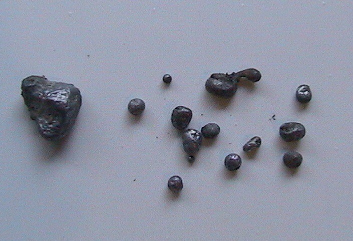
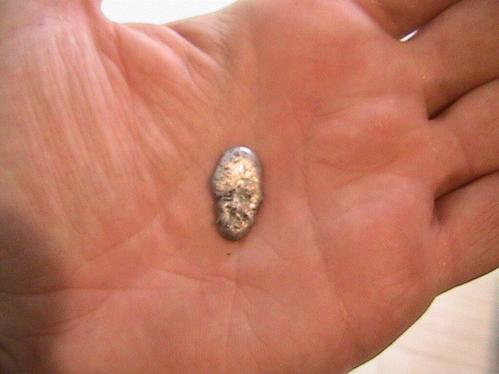
    I dug a hole about one foot in diameter, one foot deep, and conical in shape (but smooth rather than pointed at the bottom). I lined it with clay (the clay occurred naturally a few feet down in the location where I made the furnace). About one third of the way down one side I made an air inlet. I lit a wood fire in the hole to harden the clay. Once this fire had subsided I cleared out the ashes and made another larger wood fire in the furnace. I piled on a lot of wood, overflowing the top of the furnace. Once the wood on the top of the furnace had burned down, and glowing embers were left, I sprinkled coarsely crushed ore into the centre of the furnace and then raked up embers to cover it. I blew into the air inlet to raise the temperature of the furnace. I did this for perhaps 15 to 30 minutes. Once the fire had cooled (I think it had been burning for between 1 and 2 hours in total), I used a trowel to carefully remove the ashes from the fire and spread them out on a clean sheet of plastic. I recall that there were still some small charred and unburned twigs right at the bottom of the cone. Amongst the ashes I found a few small globules of tin.

    A second attempt the following day wasn't so successful, but did still result in a few small balls of tin.

  • A relay with copper contacts

    will.stevens12/11/2016 at 23:35 0 comments

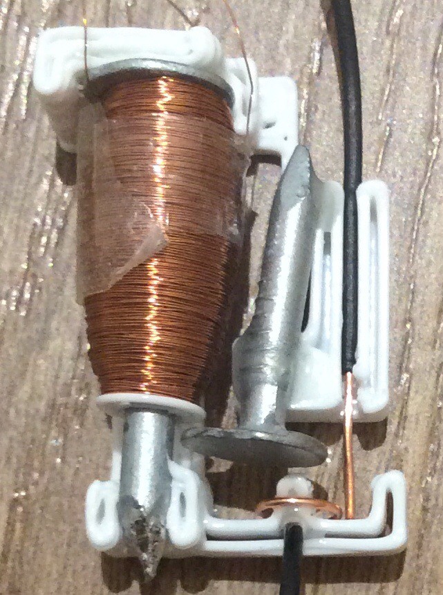
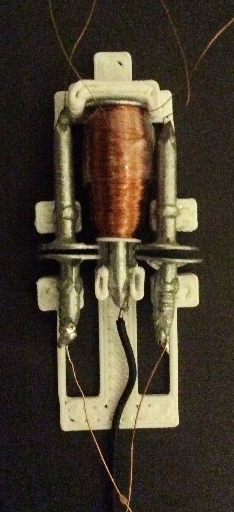
    After learning that galvanised nails are a poor choice of metal to use for relay contacts, I adapted the relay so that the contacts are separate from the nails. Copper wire is used as the contact material.

    This gives a lower contact resistance (less than 0.5 ohm) and a much more consistent performance.

    In order to be able to assess at a glance how a relay is performing, I turn the resistance measurements obtained from the automatic test setup into an image. The top image below shows the performance of a relay with galvanised nail contacts. The bottom image is from the relay pictured above with copper wire contacts. In these images, time runs from left to right across a line in the image, and each image has eight lines. Each white rectangle corresponds to closure of the contacts for half a second. The taller the rectangle, the lower the contact resistance. You can see that the contact resistance for the galvanised nail contacts is variable, whereas for the copper wire contacts it is consistent and also lower. By producing 10 such images in succession, I found that the relay above performs consistently for over 1400 operations.

  • Modulo 3 relay counter

    will.stevens10/09/2016 at 17:04 0 comments

    I made a satisfactory toggle (divide by 2) circuit that will run from a 5 Hz clock:

    Here is a video showing an attempt at making a divide by 3 circuit:

    The three large SP2ST relays are not very consistent in operation. They have 4 throws closing on a common pole, used as two throws with redundant paired contacts.

    Here is a circuit diagram for the divide by 3 circuit:

    A divide by four circuit can be made along similar lines.

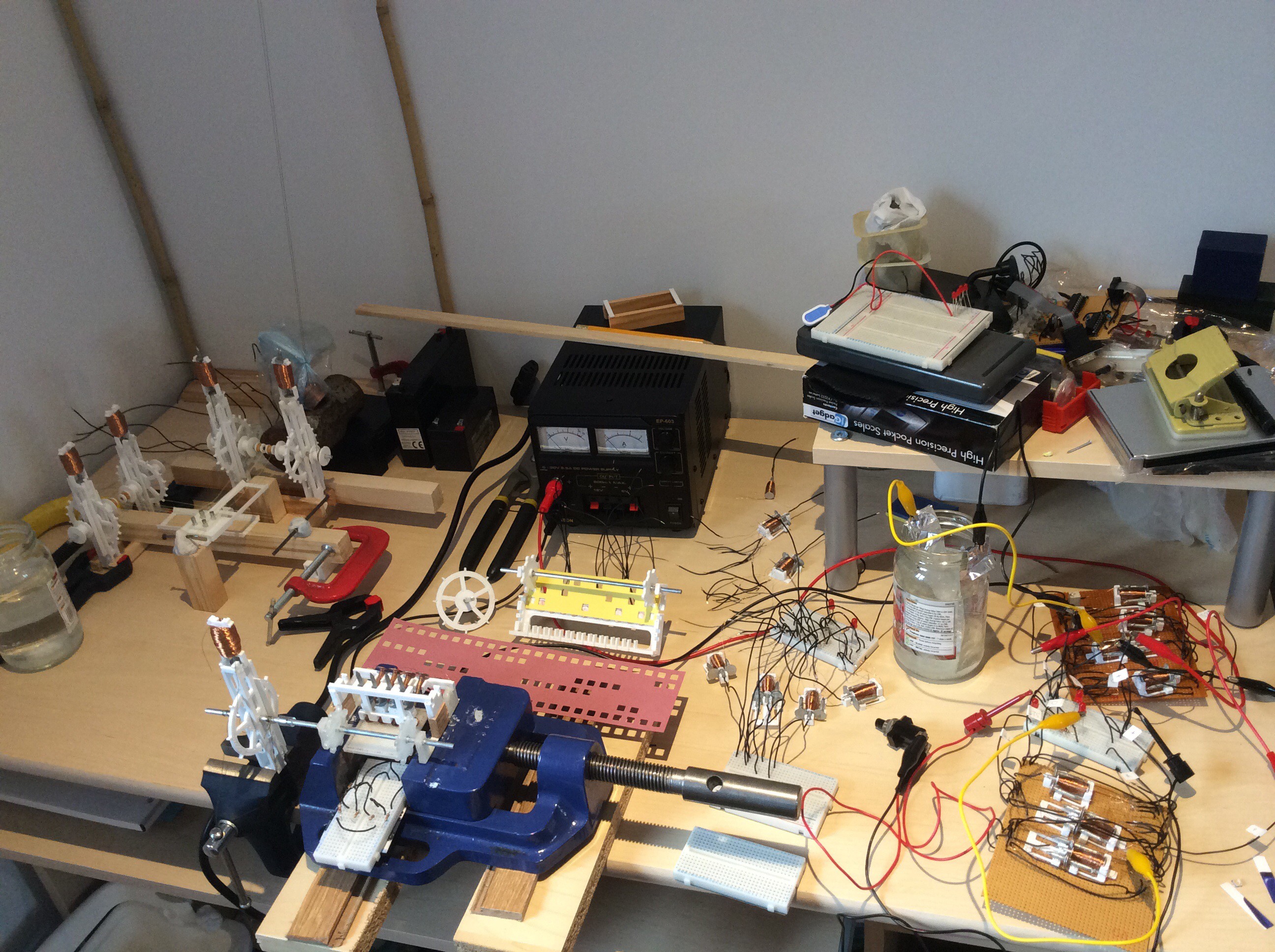
    I didn't make a working prototype plotter before the Hackaday Prize deadline, here's a photo that illustrates progress made:

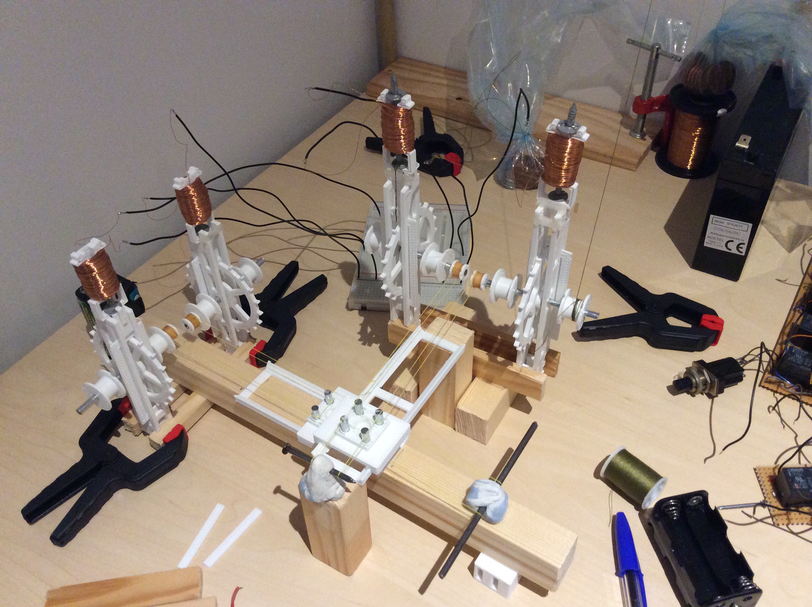
    Apart from not meeting that deadline, I'm pleased with how the project is going. After several rethinks, the control circuit design is much simpler than it was when I started thinking about it in January without sacrificing much functionality - I initially thought I'd need over 100 relays, now I think I'll need about 20. The motors work well enough to be used to drive the axes and the punched card reader. I've made a simple, working, axis movement mechanism. The punched card reader worked after only a couple of design iterations (but I haven't properly assessed how reliable it is). I'm pleased with the simplicity of the motors and the speed at which they can be stepped (at least 8 Hz) and the rate at which prototype DIY relay circuits can be clocked (at least 5 Hz).

    I need to go back to the drawing board for the relays, and spend time improving them and reducing the time that it takes to make them. One way of reducing the construction time could be to make a 3D printed coil winder that can wind several coils at once. I also want to investigate using copper or silver as contact materials, which should give better performance than galvanized nails. I also found that the clout nails I used sometimes have sharp protrusions on the shaft side of the nail head, I believe that in a few cases these were sharp enough to cut through the enamel on the copper wire and cause the coil to make contact with the nail, which I didn't notice until I came to use them.

  • Reading a punched card more reliably. Setting up X and Y axes.

    will.stevens10/03/2016 at 22:05 0 comments

    I made the tape reading mechanism more reliable by weighting down the copper nails that serve as brushes. I also made a guide to prevent them from moving more than a half a millimetre or so out of position. This video shows the mechanism reading a card containing 24 4-bit words:

    My next task is to make a 10-bit wide version of this. The card was made using a Silhouette Portrait cutter that I purchased specifically for this purpose using some of the prize money that I won for the Automation round of the 2016 Hackaday Prize.

    Meanwhile I've been setting up X and Y axes. These axes should be capable of moving a felt tipped pen across some paper.

  • 6 more coils to go

    will.stevens09/29/2016 at 22:42 0 comments

    The tedium of winding coils led me to think more about how to simplify the control circuit. I believe that I can make a modulo 12 counter circuit using 14 relays (6 SP2ST and 8 SPST), and a complete control circuit with 20 relays - I'll post a circuit diagram if it works.

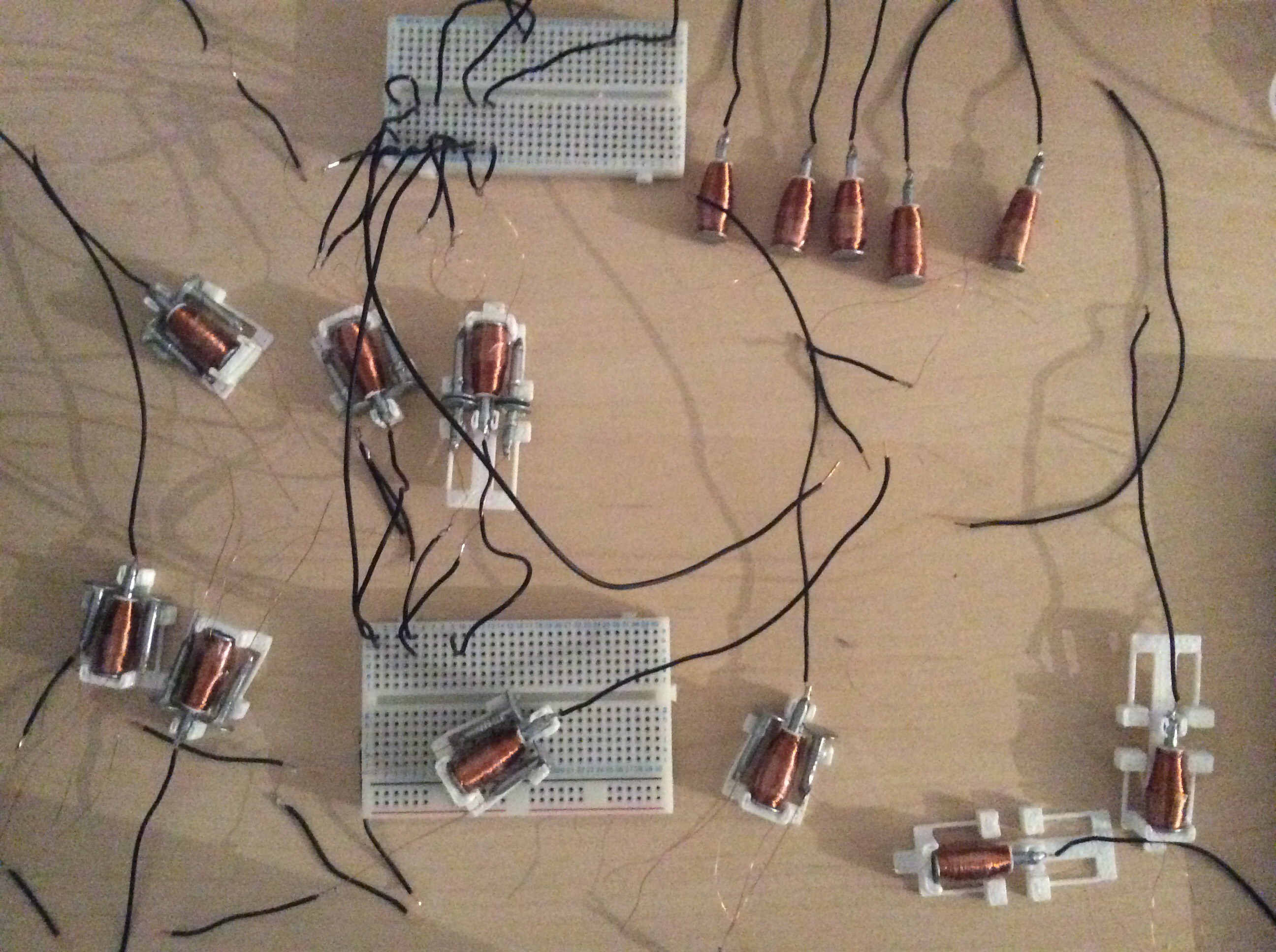
    The picture below shows progress so far on making relays:

    Some of these are SP2ST relays - the name I give to relays having two single throws which both close onto the same pole nail. Like the SPST relays, these also have redundant paired contacts for each throw:

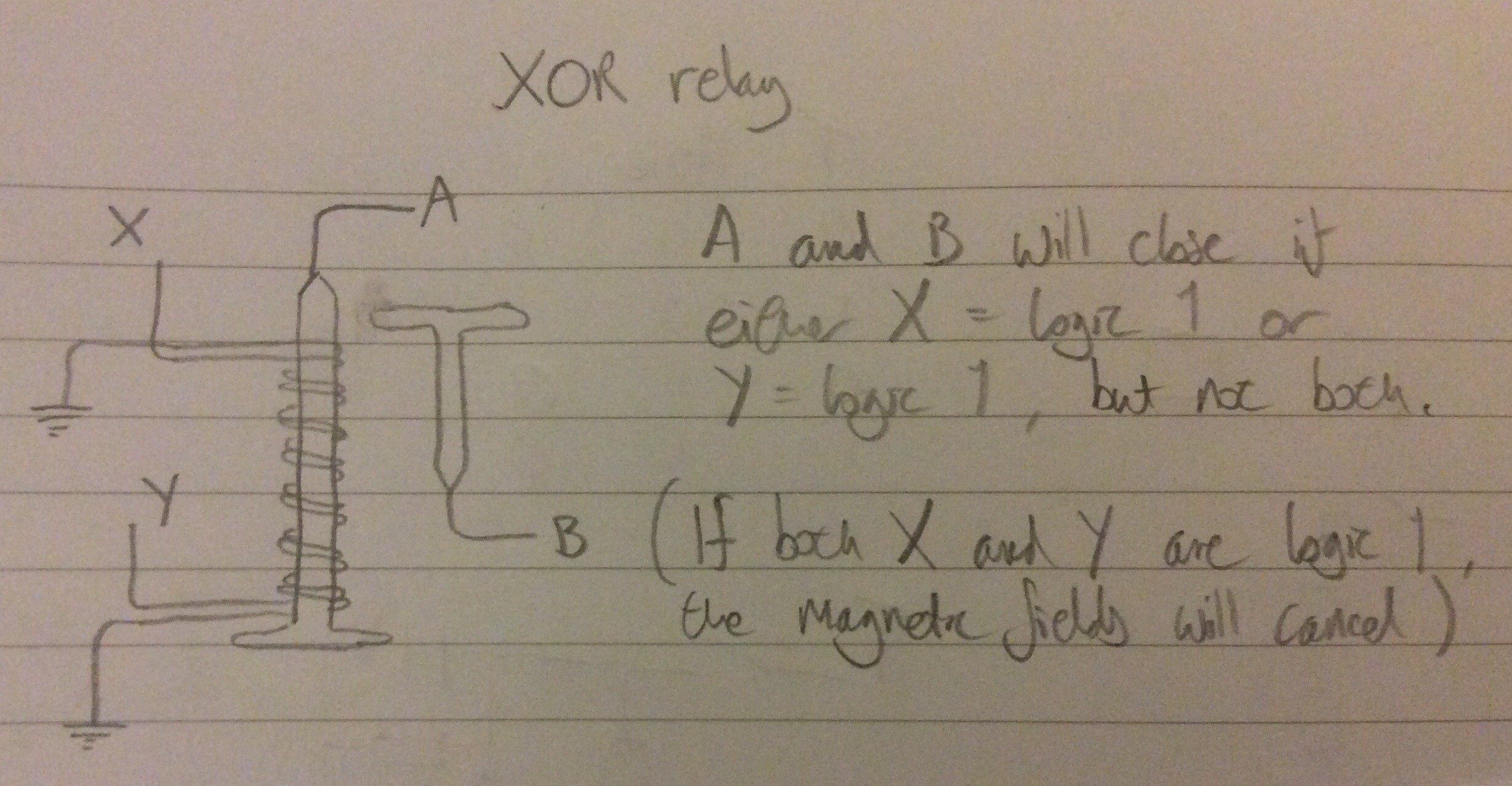
    For places where I need an XOR function, I intend to use the following:

    I've been reading a textbook about electrical contacts recently, and learned that the zinc layer on the galvanized iron nails is rather a poor choice to use for contacts - perhaps that explains why the contact resistance I'm seeing (0.5 to 2 ohms) is a lot larger than that found in commercial relays (< 0.1 ohms).

  • Reading a punched card

    will.stevens09/27/2016 at 23:01 0 comments

    Copper nails are used as brushes and contacts. These have a lower contact resistance than the galvanized iron nails used previously. The mechanism is not reliable enough yet - it advances correctly, but sometimes a brush does not make good contact - I hope that this can be improved by weighting the ends of the nails that act as brushes to give a larger contact force.

View all 30 project logs

Enjoy this project?

Share

Discussions

Matt Moses wrote 05/22/2017 at 04:38 point

Hi Will,

Do you have an estimate for how much power on average the full set of relays will require? Would it be acceptable within the context of the project to use something like a self-exciting dynamo or alternator? Being self-exciting, they would not require permanent magnets.

The dynamo could be hand-cranked, or hooked up to a stationary bike, or foot pedals (like a spinning wheel), or a windmill, or falling weights, etc.

  Are you sure? yes | no

will.stevens wrote 05/23/2017 at 22:58 point

Hi Matt, 

Average power consumption depends on the clock duty cycle, but will probably be somewhere around 10 Watts. Yes a self exciting dynamo would be okay in the context of the project. I have no experience of using or making dynamos but I imagine that one problem with this might be maintaining a constant voltage as the load changes. Batteries have the advantage that the voltage remains relatively stable if the load is not too high. I've been looking at non-rechargeable aluminium air batteries, which are simple to make (assuming that aluminium is available), but consume aluminium.

Lead acid batteries probably have a lower complexity of construction from naturally occurring materials, lead being easier to obtain from it's ore than aluminium. Rather than using a dynamo to directly power the system, it might be easier to use a dynamo to recharge lead acid batteries, because the recharging process is more tolerant of voltage variation, and has a more predictable power requirement.

  Are you sure? yes | no

Matt Moses wrote 03/03/2017 at 07:00 point

Hi Will, what did you think of Zuse's autobiography? Was there much material on self-replicating machines? And was the title of the book "The Computer - My Life"? I am considering trying to track down a copy.

Would you be willing to add a few more tags to describe this project? Perhaps some subset of "relay", "relay computer", "logic", "CNC", "plotter", "electromechanical", and/or "Zuse". I never have trouble finding other interesting and unusual relay and CNC projects on Hackaday, but this project always seems kind of hidden away. If I wasn't looking for it I'm not sure I could find it!

  Are you sure? yes | no

will.stevens wrote 03/19/2017 at 18:26 point

Hi Matt, Yes it was "The Computer - My Life". It's well worth reading. There wasn't much technical detail about his work on self-replicating machines. There are about 6 or 7 pages of discussion about it. In 1966 he built 'an assembly line in the context of self-reproducing systems', and the book includes a photo - I want to try and find more details about this. I don't believe it is mentioned in Freitas & Merkle's KSRM (I've just had a look and can't see it, although there is a paragraph by Zuse about self-replication on p25).

Thanks for the advice about tags - I'll add those.

  Are you sure? yes | no

Starhawk wrote 02/25/2017 at 05:22 point

...hey, you stopped. What happened?

  Are you sure? yes | no

will.stevens wrote 03/19/2017 at 18:08 point

I've slowed down a little - other more important projects at the moment, but this one is still on the back burner.

  Are you sure? yes | no

will.stevens wrote 12/11/2016 at 23:57 point

Hi Starhawk, I haven't given up - see latest post about a better relay. I read Zuse's autobiography recently (I had come across his relay computers before but hadn't read his autobiography) - very interesting. I was interested in his thoughts about self-replicating machines, and also the Graphomat Z64, an early digital plotter controlled by punched tape.

  Are you sure? yes | no

Starhawk wrote 12/12/2016 at 00:33 point

Very cool! I saw that there was a bit of inactivity, so I thought I'd send you some words of encouragement. This is an extremely awesome project.

Kudos on the improved relay, of course :)

  Are you sure? yes | no

Starhawk wrote 11/16/2016 at 03:24 point

Hey, don't give up yet :)

  Are you sure? yes | no

Starhawk wrote 09/13/2016 at 23:59 point

Has anyone told you yet how freaking brilliant you are, to be working this out like this?

Also -- someone you should look up. Konrad Zuse. Pay particular attention to the schematic for his two-relay (well, two-4PDT relay!) full 1b adder, and to his Z3 and Z4 computers. After all, you're using his tech -- relays.

EDIT: how the #@*!! do I +skull this project when the button's gone?! NO FAIR, I SAY, NO FAIR.

  Are you sure? yes | no

Starhawk wrote 09/17/2016 at 01:11 point

Figured it out. Some miscreant moved the +skull button and called it "like". Hey Mr Miscreant -- this ain't Facebook. If it was, I wouldn't be here.

  Are you sure? yes | no

will.stevens wrote 09/17/2016 at 08:09 point

Thanks, one of the things that I find impressive about the Z4 is that the clock speed was 40Hz and the performance on floating point arithmetic was only 100-1000 times slower than some bit-serial electronic computers built 15 years later.

The reliability of relay computers is also impressive (for their time). This article about the Harwell computer / WITCH says that it could run for days at a time: https://en.wikipedia.org/wiki/Harwell_computer

  Are you sure? yes | no

Starhawk wrote 09/20/2016 at 21:56 point

Thanks for the thanks!

I was somehow unaware that the WITCH had relays in it. You know it's still running...? I wish I could see it in person, but I'm in the States and unable to travel...

  Are you sure? yes | no

cuyler wilkinson wrote 08/31/2016 at 23:34 point

My dad had a home made hand crank coil winder with the thumb counter where "I"(Oh! No! not  the other 3 siblings) wound  many coils to build electric etching pencils back in the early 60's. he sold them at the paper mill he worked at. 3000 turns on each one! 

  Are you sure? yes | no

cuyler wilkinson wrote 08/30/2016 at 18:02 point

I love the project.

I didn't see any diodes in your relay schematic. Are they there? If not diodes will stop the relay back EMF and "chatter".  They are listed as relay protection diodes. Maybe someone else will chime in with a better drain source to eliminate the magnetic effects from all those relays knitted so closely together. Perhaps a braided bond wire to ground connecting all the protective diodes? Maybe this will help!

  Are you sure? yes | no

will.stevens wrote 08/31/2016 at 22:10 point

You're right that the schematic has no diodes. In the circuits that I made from off the shelf relays I didn't use any snubber, and as a consequence the relays won't last as long and have a greater chance of contacts welding closed. In the circuits made with homemade nail & wire relays I've used an aluminium foil & sodium bicarbonate capacitor as a snubber in places where that is needed. In a future log post - once I've done the experiments to characterize them - I'll post details about the aluminium foil & sodium bicarbonate capacitors. In this video you can see contact arcing when the snubber is disconnected. I hope to avoid using diodes, because they are difficult to make from scratch. I think that it is possible to make point contact diodes, but I've read that it can be tricky to find and keep a reliable point of contact.

  Are you sure? yes | no

Matt Moses wrote 09/20/2016 at 22:14 point

Since the capacitors are electrochemical, it is possible that they are already acting like diodes. Common electrolytic capacitors will conduct electricity when reverse-biased, right? 

  Are you sure? yes | no

will.stevens wrote 09/22/2016 at 21:08 point

Hi Matt

Yes they do a little - if I apply a voltage to one, I get an initial surge of current as you expect with a capacitor, then the current reduces to a steady 1 or 2 mA. If I then reverse the polarity, the steady state current is about twice as large. I don't have a proper oscilloscope at the moment so can't see exactly what is happening. They are quite difficult to characterize because they change constantly. I believe that I read somewhere that it takes some time for an oxide layer to build up on the aluminium, and perhaps that is happening as I'm using them.

(I don't know why I don't get a reply button under your reply - I'm not sure exactly where what I'm typing will appear).

  Are you sure? yes | no

Ryan wrote 08/21/2016 at 20:51 point

I love this project! You have the full spirit of scientific history behind you, you can't lose! Please keep up the good work!

  Are you sure? yes | no

Similar Projects

Does this project spark your interest?

Become a member to follow this project and never miss any updates