will.stevens
-
Making batteries
05/09/2017 at 17:47 • 0 commentsOne of the problems that remains to be solved in this project is how to provide electrical power to the system without greatly increasing the range of materials needed for the complete system. Plugging it into the wall wouldn't do, since this would depend upon the electricity generation and distribution infrastructure.
Homemade batteries seem like a promising alternative. Some batteries are very easy to construct, and will provide a constant voltage.
Googling homemade batteries and 19th century batteries leads me to believe that two promising alternatives are aluminium-air batteries (https://en.m.wikipedia.org/wiki/Aluminium-air_battery) and batteries using the gravity cell variant of the Daniell cell (https://en.m.wikipedia.org/wiki/Daniell_cell).
In terms of the simplicity of their construction, and the range of materials used in their construction, there is little to choose between them. The gravity cell requires copper sulphate, which is non-trivial to produce from raw materials. The aluminium-air battery requires activated charcoal, which I believe can be made from charcoal treated with an acid or alkali. I have a slight preference for the aluminium-air battery. I believe that potassium hydroxide solution (an alkali) can be obtained from wood ash, so this is a possible route for the production of activated charcoal.
Below is a video showing my first attempt to make an aluminium-air battery:
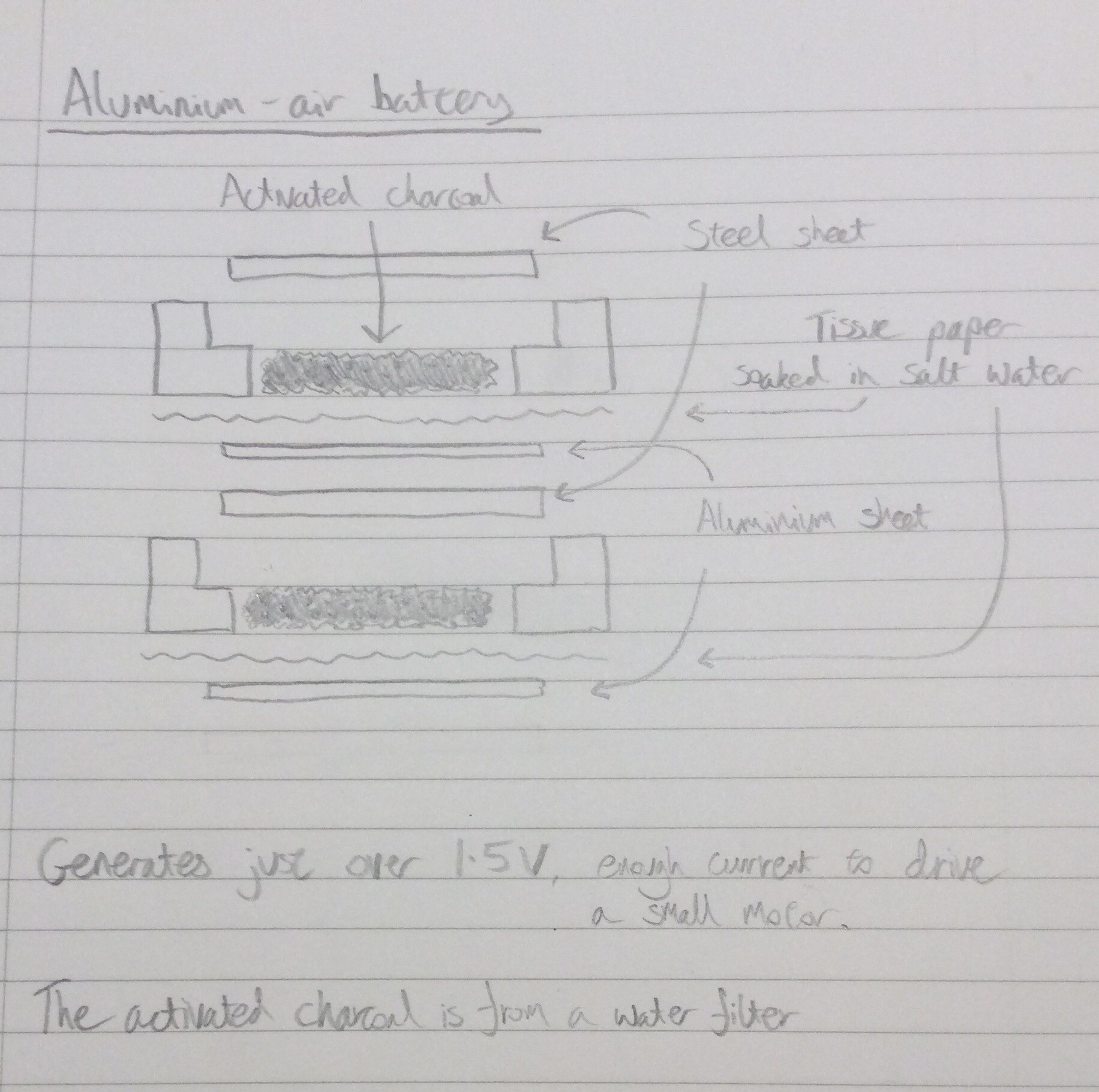
Here is a diagram showing how the battery is constructed:
![]()
A battery of six of these cells, with a surface area about twice as large as shown in the video, should be able to activate a single relay.
-
A divide by 3 circuit using copper contact relays
04/23/2017 at 08:56 • 1 commentThe video below shows relays with copper contacts being used to make a divide by 3 circuit. This is much more successful than my earlier attempt to make the same circuit (part of project log dated 10th Oct 2016). The copper contact relays operate from a lower voltage than my earlier relays, partly because I've become better at assembling them, partly because the new relays only require one nail per contact, whereas previously I had to double-up to compensate for the unreliability of the nail-nail contacts.
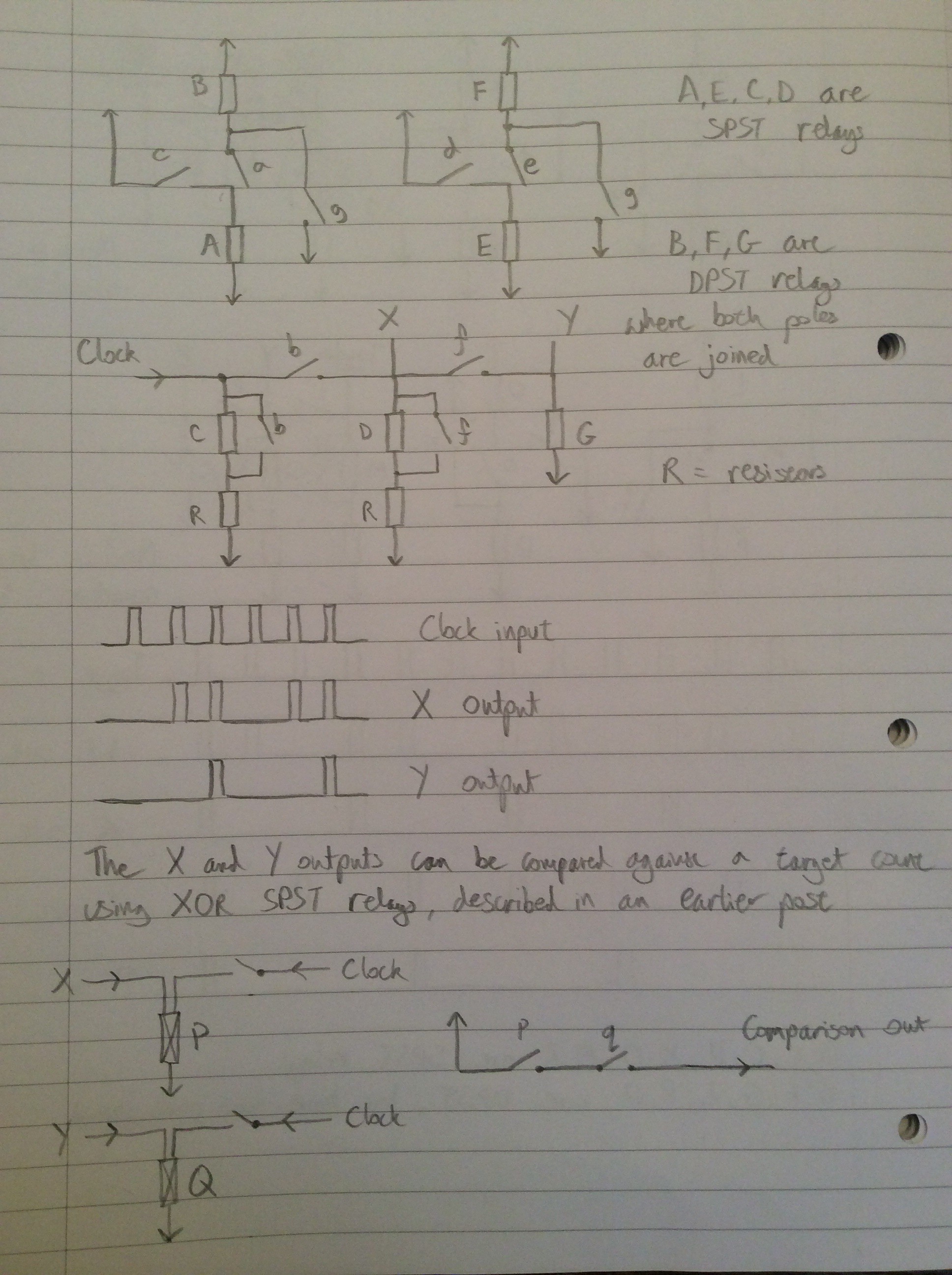
Below is the circuit diagram, repeated from the 10th Oct 2016 log entry:
![]()
Relays (A,B) behave like a trailing-edge driven set/reset circuit, where C provided the set signal and G provides the reset signal. The contacts of B change state immediately after removal of the set or reset pulse. Relays (E,F) are a similar circuit. The network of relays and resistors involving relays C,D and G route the clock signal to the appropriate place depending on the state of relays B and F.
E.g. If neither B nor F are active, the clock signal is routed to set (A,B). If B is active but F isn't then the clock is routed to set (E,F). If both B and F are active then the clock is routed to reset both.
Below is a video of the same circuit stepping a motor on every third clock pulse:
-
An oscillator driving a toggle flip flop
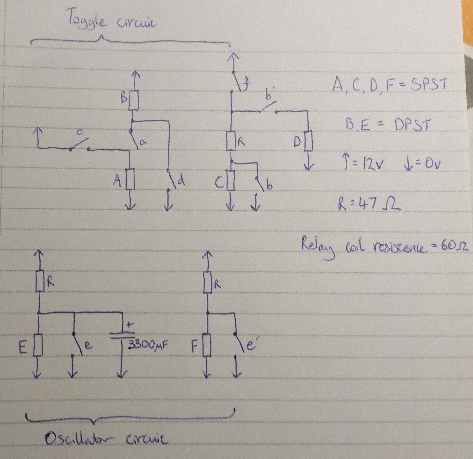
04/14/2017 at 08:26 • 1 commentThis video and circuit diagram show an oscillator driving a toggle flip flop. The oscillator is to the right of the video.
![]()
The oscillator uses a capacitor to delay the closing of a relay which, when closed, discharges the capacitor and deactivates the relay, starting the next cycle. A DPST relay is used so that the second pair of contacts can be used to generate a clock signal. Perhaps because the DPST relay has slow contact closure due to gradual charging of the capacitor, I found that it could not be used directly for the clock signal, so a second relay is used to buffer (and also invert) the signal.
A 3300 microfarad off-the-shelf capacitor is used in the oscillator. I'd like to replace this with a homemade equivalent, or come up with an alternative (possibly mechanical) oscillator design that doesn't require a high value capacitor.
-
Toggle flip flop using new relay
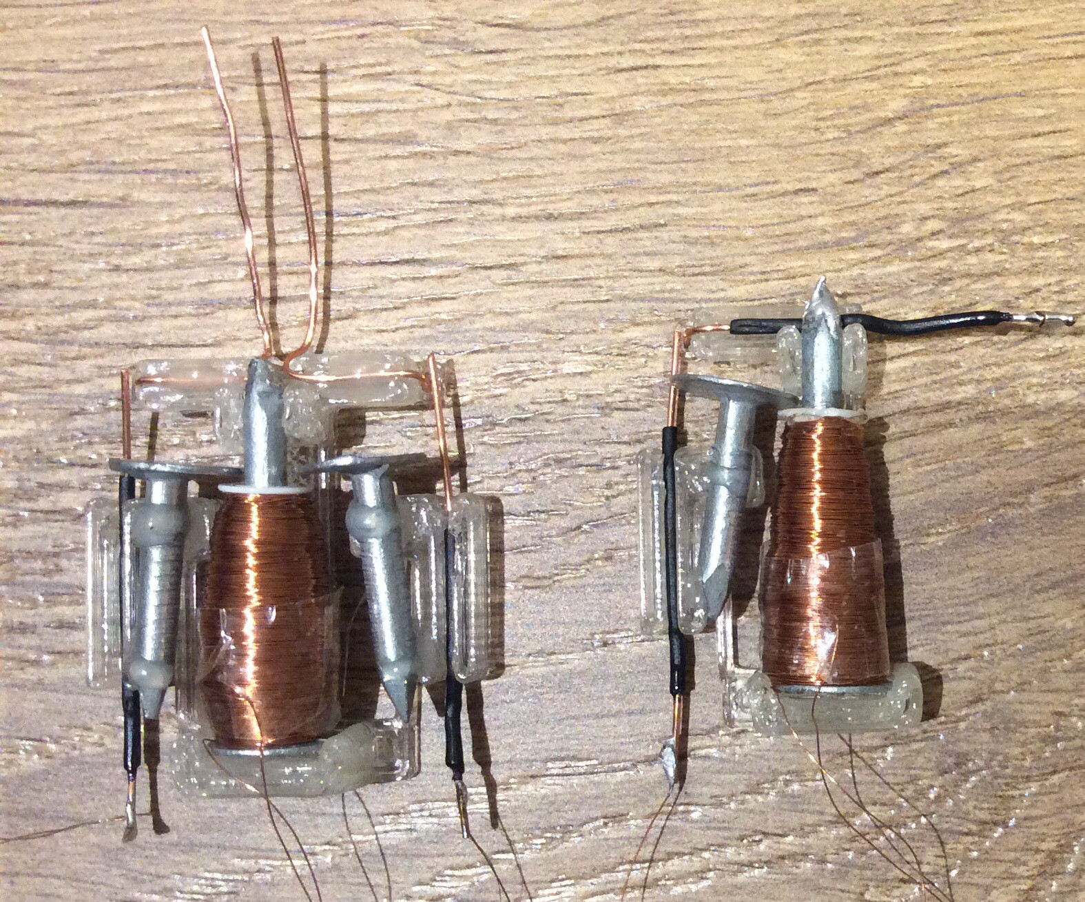
04/02/2017 at 21:43 • 2 commentsThis video shows a toggle flip flop made from copper contact relays. Initially there was a problem with oscillation of the relay contacts after the relay opens: because the contact separation distance is less than the nail-nail distance, it is possible for the contacts to re-contact after opening as the nail vibrates briefly after the contact opens. Only the DPST relay exhibited this problem, and it was solved by bending a piece of insulated wire in such a way that after opening, a contact hits the wire, damping the oscillation enough to prevent the problem.
Here is a close-up photo of two of the relays (before the damping solution had been implemented for the DPST relay):
![]()
-
Making metal
12/26/2016 at 20:28 • 1 commentI came across some photos earlier today that are relevant to this project. This project involves using as few raw materials as possible, and using raw materials that are as simple as possible. How exactly the simplicity of a raw material should be defined is a difficult question to answer: simple with respect to what? A context must be given.
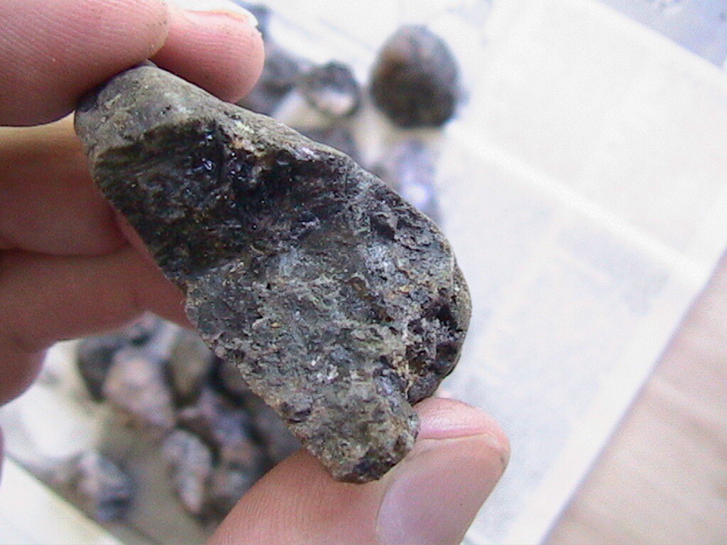
In the south west of England there are a wide range of natural resources available. There are locations in the southwest where ores of copper, tin, lead and iron can be found within a few dozen miles of each other. A few years ago I found some tin ore (cassiterite) and had a go at smelting it.
I didn't keep a detailed record at the time of how I went about this. The account below is to the best of my recollection.
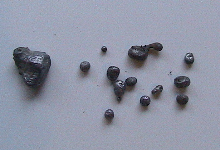
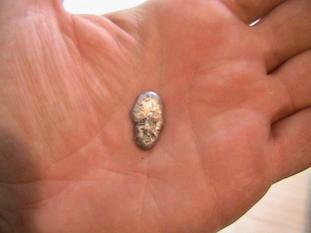
I dug a hole about one foot in diameter, one foot deep, and conical in shape (but smooth rather than pointed at the bottom). I lined it with clay (the clay occurred naturally a few feet down in the location where I made the furnace). About one third of the way down one side I made an air inlet. I lit a wood fire in the hole to harden the clay. Once this fire had subsided I cleared out the ashes and made another larger wood fire in the furnace. I piled on a lot of wood, overflowing the top of the furnace. Once the wood on the top of the furnace had burned down, and glowing embers were left, I sprinkled coarsely crushed ore into the centre of the furnace and then raked up embers to cover it. I blew into the air inlet to raise the temperature of the furnace. I did this for perhaps 15 to 30 minutes. Once the fire had cooled (I think it had been burning for between 1 and 2 hours in total), I used a trowel to carefully remove the ashes from the fire and spread them out on a clean sheet of plastic. I recall that there were still some small charred and unburned twigs right at the bottom of the cone. Amongst the ashes I found a few small globules of tin.
A second attempt the following day wasn't so successful, but did still result in a few small balls of tin.
![]()
![]()
![]()
![]()
-
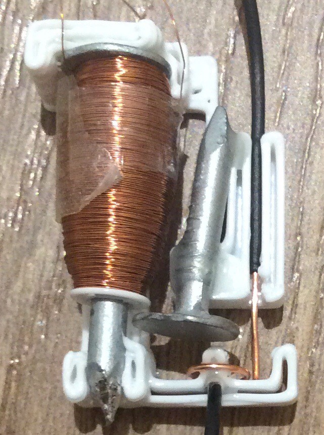
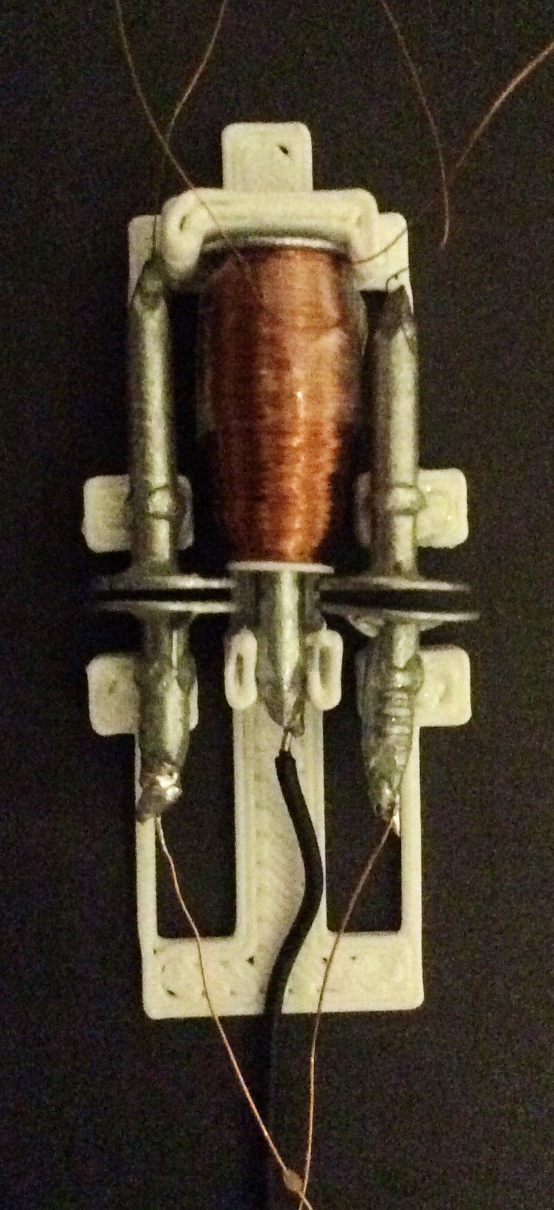
A relay with copper contacts
12/11/2016 at 23:35 • 0 commentsAfter learning that galvanised nails are a poor choice of metal to use for relay contacts, I adapted the relay so that the contacts are separate from the nails. Copper wire is used as the contact material.
This gives a lower contact resistance (less than 0.5 ohm) and a much more consistent performance.
![]()
In order to be able to assess at a glance how a relay is performing, I turn the resistance measurements obtained from the automatic test setup into an image. The top image below shows the performance of a relay with galvanised nail contacts. The bottom image is from the relay pictured above with copper wire contacts. In these images, time runs from left to right across a line in the image, and each image has eight lines. Each white rectangle corresponds to closure of the contacts for half a second. The taller the rectangle, the lower the contact resistance. You can see that the contact resistance for the galvanised nail contacts is variable, whereas for the copper wire contacts it is consistent and also lower. By producing 10 such images in succession, I found that the relay above performs consistently for over 1400 operations.
![]()
![]()
-
Modulo 3 relay counter
10/09/2016 at 17:04 • 0 commentsI made a satisfactory toggle (divide by 2) circuit that will run from a 5 Hz clock:
Here is a video showing an attempt at making a divide by 3 circuit:
The three large SP2ST relays are not very consistent in operation. They have 4 throws closing on a common pole, used as two throws with redundant paired contacts.
Here is a circuit diagram for the divide by 3 circuit:
![]()
A divide by four circuit can be made along similar lines.
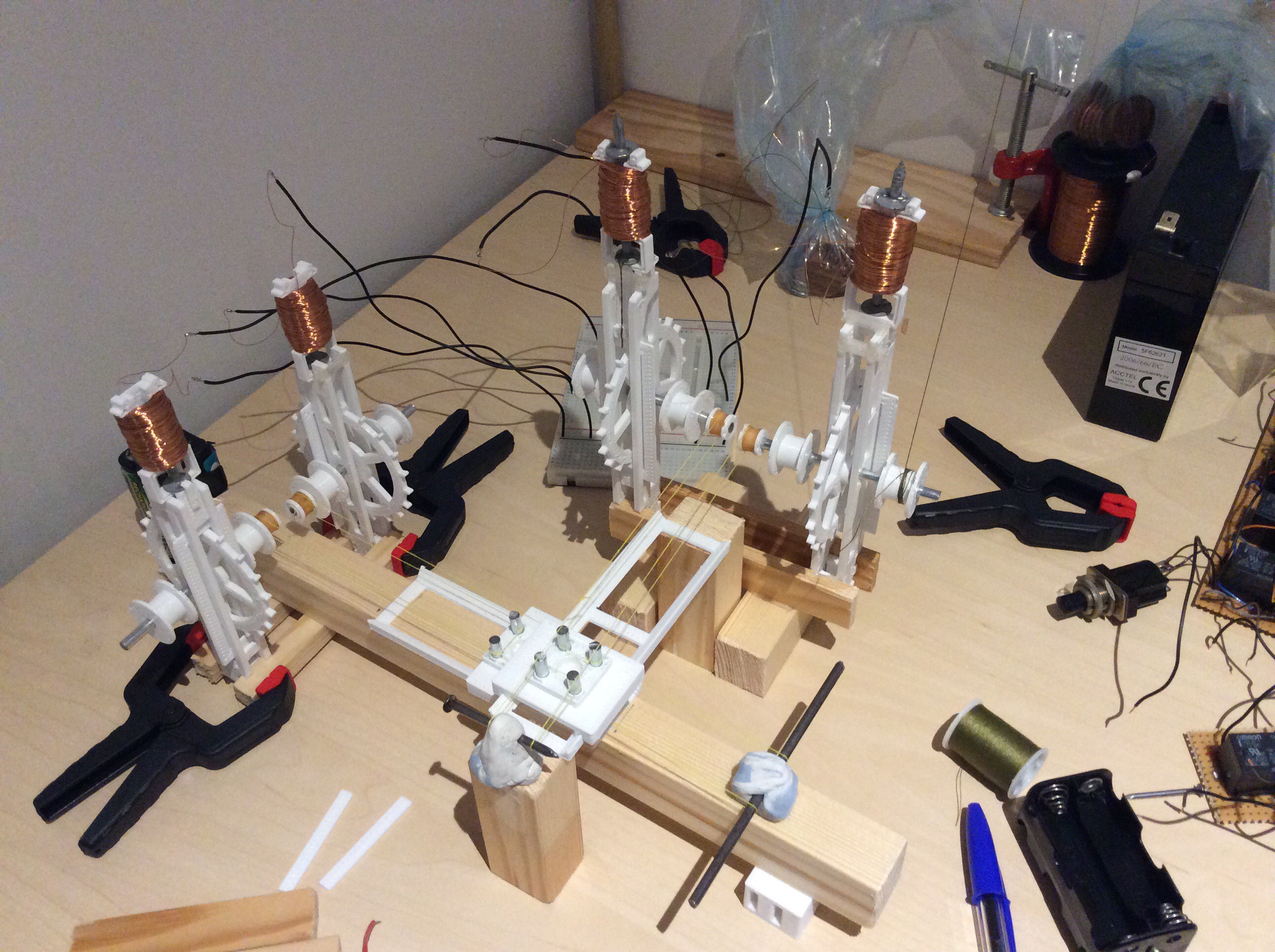
I didn't make a working prototype plotter before the Hackaday Prize deadline, here's a photo that illustrates progress made:
![]()
Apart from not meeting that deadline, I'm pleased with how the project is going. After several rethinks, the control circuit design is much simpler than it was when I started thinking about it in January without sacrificing much functionality - I initially thought I'd need over 100 relays, now I think I'll need about 20. The motors work well enough to be used to drive the axes and the punched card reader. I've made a simple, working, axis movement mechanism. The punched card reader worked after only a couple of design iterations (but I haven't properly assessed how reliable it is). I'm pleased with the simplicity of the motors and the speed at which they can be stepped (at least 8 Hz) and the rate at which prototype DIY relay circuits can be clocked (at least 5 Hz).
I need to go back to the drawing board for the relays, and spend time improving them and reducing the time that it takes to make them. One way of reducing the construction time could be to make a 3D printed coil winder that can wind several coils at once. I also want to investigate using copper or silver as contact materials, which should give better performance than galvanized nails. I also found that the clout nails I used sometimes have sharp protrusions on the shaft side of the nail head, I believe that in a few cases these were sharp enough to cut through the enamel on the copper wire and cause the coil to make contact with the nail, which I didn't notice until I came to use them.
-
Reading a punched card more reliably. Setting up X and Y axes.
10/03/2016 at 22:05 • 0 commentsI made the tape reading mechanism more reliable by weighting down the copper nails that serve as brushes. I also made a guide to prevent them from moving more than a half a millimetre or so out of position. This video shows the mechanism reading a card containing 24 4-bit words:
My next task is to make a 10-bit wide version of this. The card was made using a Silhouette Portrait cutter that I purchased specifically for this purpose using some of the prize money that I won for the Automation round of the 2016 Hackaday Prize.
Meanwhile I've been setting up X and Y axes. These axes should be capable of moving a felt tipped pen across some paper.
![]()
-
6 more coils to go
09/29/2016 at 22:42 • 0 commentsThe tedium of winding coils led me to think more about how to simplify the control circuit. I believe that I can make a modulo 12 counter circuit using 14 relays (6 SP2ST and 8 SPST), and a complete control circuit with 20 relays - I'll post a circuit diagram if it works.
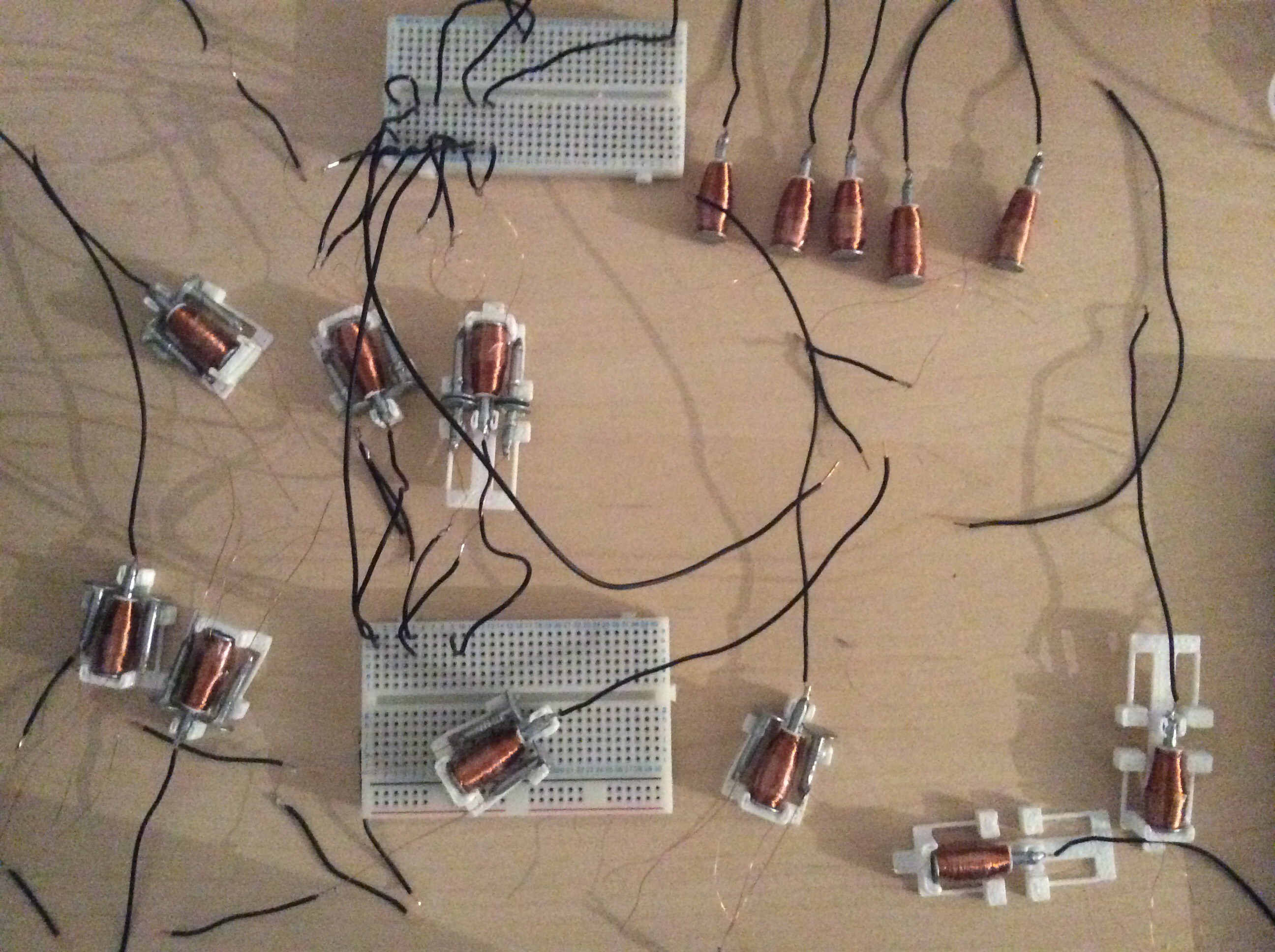
The picture below shows progress so far on making relays:
![]()
Some of these are SP2ST relays - the name I give to relays having two single throws which both close onto the same pole nail. Like the SPST relays, these also have redundant paired contacts for each throw:
![]()
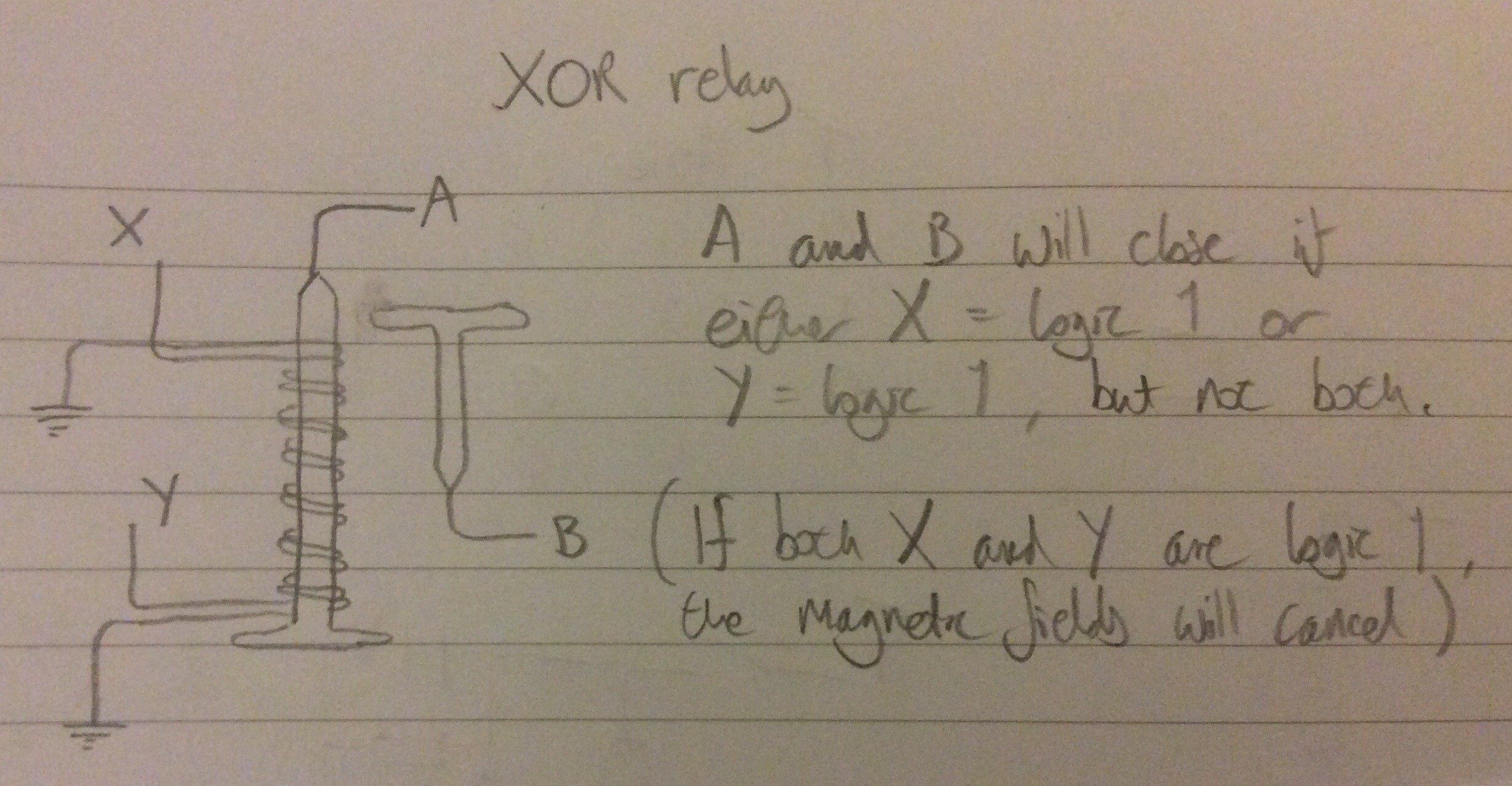
For places where I need an XOR function, I intend to use the following:
![]()
I've been reading a textbook about electrical contacts recently, and learned that the zinc layer on the galvanized iron nails is rather a poor choice to use for contacts - perhaps that explains why the contact resistance I'm seeing (0.5 to 2 ohms) is a lot larger than that found in commercial relays (< 0.1 ohms).
-
Reading a punched card
09/27/2016 at 23:01 • 0 commentsCopper nails are used as brushes and contacts. These have a lower contact resistance than the galvanized iron nails used previously. The mechanism is not reliable enough yet - it advances correctly, but sometimes a brush does not make good contact - I hope that this can be improved by weighting the ends of the nails that act as brushes to give a larger contact force.
RelayRepRap
This project is about exploring whether it is possible to make a RepRap control system that can be made by a RepRap.