Here is a rather uninteresting video showing a toggle flip-flop driven from an approx 1.5Hz signal toggling for 5 minutes:
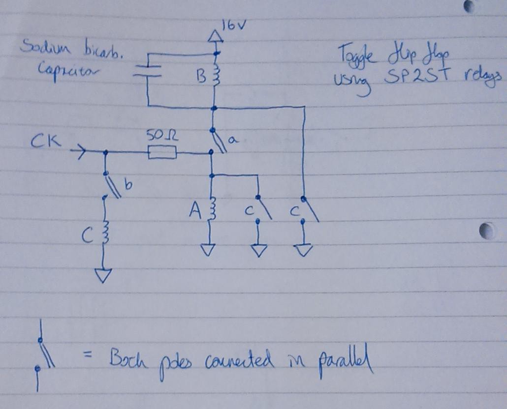
Here is a circuit diagram:

The clock signal comes from a clock circuit made from a pair of off-the-shelf SPDT relays (off to the right of the video - the two electrolytic capacitors are part of the clock circuit).
The circuit fails to toggle at 1:36 and again at 4:00. I'm not sure yet whether the failure is due to bad circuit design or problems with the relays, or a mixture of both. The way that it fails is that relay A doesn't turn off when it should - one of the pole nails remains in contact with the coil nail. I can think of several reasons why this could happen - further work is needed to find the problem.
The reason why toggle flip-flops are relevant to this project is that the control circuit described the file 'controller_explanation.pdf' in the 'FILES' section of this project is based around them - the largest part of the control circuit consists of four toggle flip-flops configured as a divide by 3 and divide by 4 counter. A version of this circuit using off-the-shelf DPST relays can be seen here.
 will.stevens
Discussions
Become a Hackaday.io Member
Create an account to leave a comment. Already have an account? Log In.