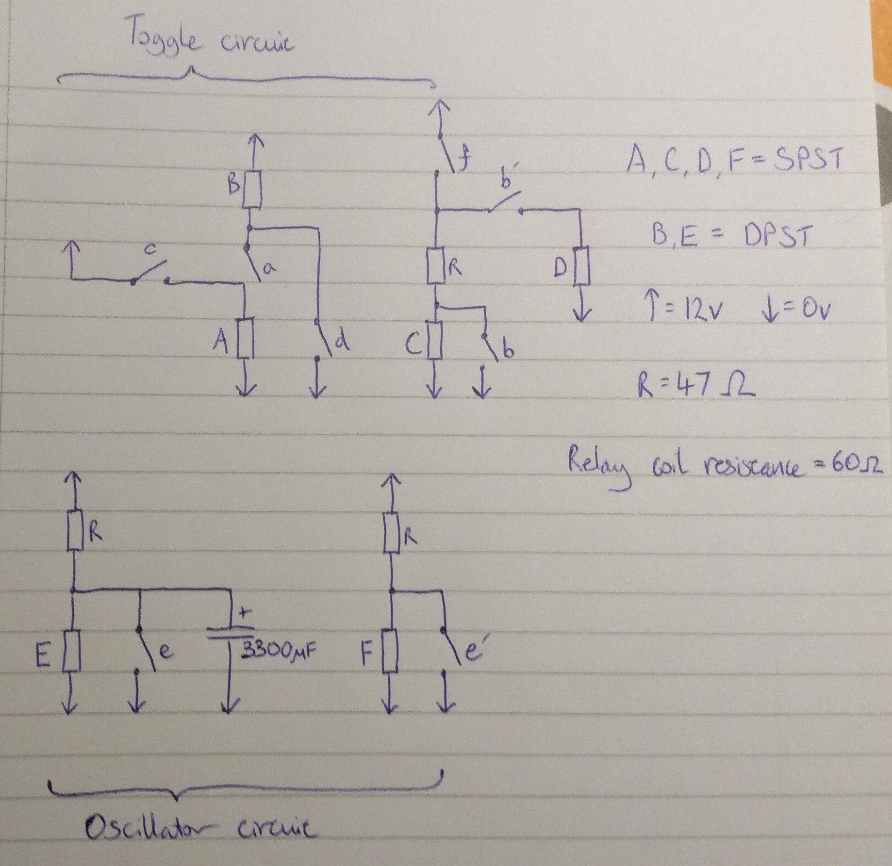
This video and circuit diagram show an oscillator driving a toggle flip flop. The oscillator is to the right of the video.

The oscillator uses a capacitor to delay the closing of a relay which, when closed, discharges the capacitor and deactivates the relay, starting the next cycle. A DPST relay is used so that the second pair of contacts can be used to generate a clock signal. Perhaps because the DPST relay has slow contact closure due to gradual charging of the capacitor, I found that it could not be used directly for the clock signal, so a second relay is used to buffer (and also invert) the signal.
A 3300 microfarad off-the-shelf capacitor is used in the oscillator. I'd like to replace this with a homemade equivalent, or come up with an alternative (possibly mechanical) oscillator design that doesn't require a high value capacitor.
 will.stevens
Discussions
Become a Hackaday.io Member
Create an account to leave a comment. Already have an account? Log In.
just wow.
Are you sure? yes | no